Waveguide Cable Applications in Radar and Satellite Systems
In radar and satellite systems, sending signals reliably at high frequencies is still very important for mission success. Waveguide cable systems are special kinds of communication lines that let electromagnetic waves travel at high speeds and with little loss at microwave and millimeter-wave frequencies. These strong and flexible parts connect hard waveguide sections in complicated setups where there are problems with alignment, mechanical movement, or heat expansion. Waveguide cables keep the integrity of signals across bands up to 110 GHz, while traditional coaxial cables have trouble above 18 GHz. This makes them essential for current defense, aerospace, and telecommunications systems.
Understanding Waveguide Cables and Their Role in Radar and Satellite Systems
Waveguide cables represent the next major evolution in RF transmission technology. They combine the best electrical performance of rigid waveguides with the mechanical freedom that is needed in real-world setups. At Advanced Microwave Technologies Co., Ltd., we've seen how these parts solve important technical problems in a wide range of settings.
Working Principles and Construction
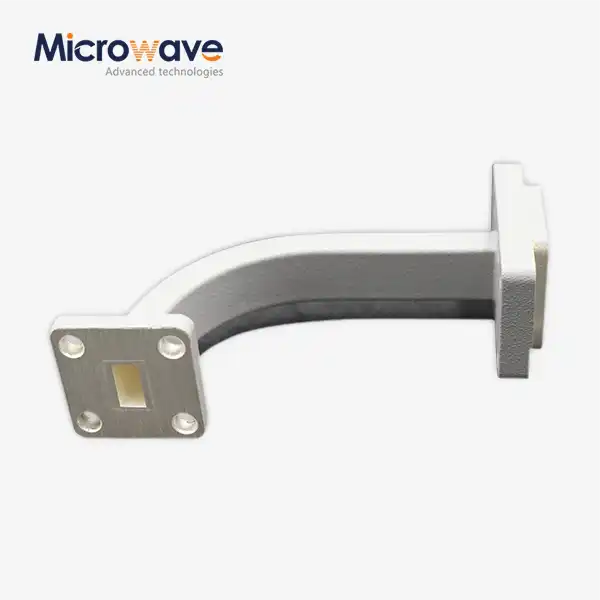
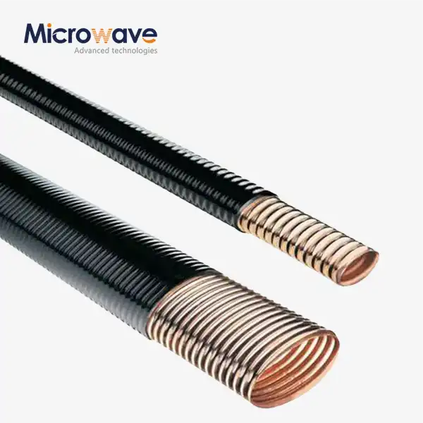
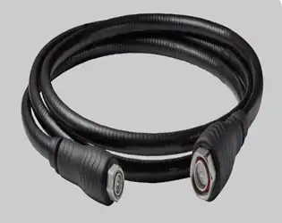
Waveguide cables work with TE (Transverse Electric) or TM (Transverse Magnetic) modes inside a hollow metal frame, while coaxial cables use TEM (Transverse Electromagnetic) mode transmission. The complicated core structure, which is usually made of copper or brass that has been silver-plated, lets the wire bend and twist while still keeping the electromagnetic boundary conditions needed for signal transfer. This overlapping shape makes a continuous conductive path that keeps electromagnetic energy inside the structure, stopping radiation loss and interference from outside. For outdoor locations, protective jacketing can be made of waterproof Neoprene. For lab settings, it can be made of polished metal housings.
Frequency Ranges and Technical Specifications
Waveguide cables work with a wide range of frequencies that match normal waveguide sizes. The WR-90 configuration works with X-Band (8.2-12.4 GHz), which is often used in marine radar and weather tracking systems. WR-28 waveguides are used for uplink and downstream communications in Ka-Band devices that work at 26.5 to 40 GHz. We check performance by looking at insertion loss (which should be less than 0.5 dB per meter depending on frequency), voltage standing wave ratio (which should be kept below 1.25:1), and power-handling capacity that is much higher than cable options. In phased array radar systems, where signal coherence directly affects beam direction accuracy, phase stability during flexure is a very important property that is often ignored.
Advantages Over Alternative Transmission Media
When procurement experts look at the different types of transmission lines for bands above 18 GHz, waveguide cables stand out as the best choice. At 40 GHz, waveguide assemblies have about a tenth of the insertion loss of high-performance coaxial wires, but they can handle much higher amounts of continuous and peak power without getting hot. The enclosed structure naturally blocks electromagnetic fields, so there are no worries about crosstalk in thick RF systems. Longer working life is improved by mechanical robustness; our assemblies regularly survive millions of flex cycles without losing their electrical performance. Because of these traits, the system is very reliable, which is a must for defense companies and satellite providers because downtime has very bad operational and financial effects.
Critical Applications of Waveguide Cables in Radar and Satellite Technologies
The versatility of waveguide cable arrangements shows how flexible they are in many high-stakes situations where signal integrity can't be compromised.
Radar Signal Transmission and Reception
Military and private radar systems use waveguide cables to link transceiver equipment that stays in one place with rotating antenna units. These flexible links are used by airborne early warning aircraft to connect gimbaled radar arrays to electronics placed on the body. This allows the aircraft to move continuously while still accurately detecting targets. When naval ships are in harsh conditions like salt spray, high temperatures, and constant vibration, waveguide cables protect against mechanical stress and the environment in a way that hard plumbing can't. Ground-based air traffic control systems use waveguide assemblies to make maintenance easier. This is because they let workers disconnect and repair parts without affecting the whole RF chain.
Satellite Ground Station Infrastructure
Waveguide cables are used all the way through the signal chains of earth stations that serve private and government satellite networks. These parts link high-power amplifiers (HPAs) that make kilowatts of RF energy to antenna feed systems. They control power levels that would destroy coaxial options in seconds. The Ku-Band (12-18 GHz) and Ka-Band setups we've supplied to telecommunications providers show that waveguide cables can handle temperature changes of up to 70°C (-40°F) outside without losing their electrical performance. Waveguide cable technology works well at scaling as satellite companies move to higher frequency bands to get more bandwidth. Fiber optic options, on the other hand, can't do the same for sending high-power RF signals.
Emerging Technologies and 5G Infrastructure
Waveguide technology works well for solving the new problems that come up with next-generation transmission systems. Millimeter-wave 5G base stations that work in the 24–40 GHz range need links between distant radio heads and antenna elements that have low loss. We've worked with companies that make telecommunications equipment to create huge MIMO (Multiple Input Multiple Output) systems with radome sizes that are limited and dozens of waveguide cables that must fit. When there are various signal paths, phase stability and amplitude consistency are very important for beamforming methods that change the direction of coverage on the fly. In the same way, automobile radar systems for self-driving cars are using waveguide technology more and more as the frequency range goes up to 76–81 GHz, and standard interconnects can't keep up.
Comparing Waveguide Cables with Alternative Transmission Lines for High-Frequency B2B Solutions
To make smart choices about where to get things, procurement managers need to know how the different transmission technologies compare in terms of performance.
Waveguide Versus Coaxial Cable Performance
When the frequency is less than 10 GHz, good coaxial lines work well enough, are more flexible mechanically, and cost less at first. However, physics says that the attenuation of a coaxial wire grows greatly with frequency. This is a basic problem that can't be fixed by engineering. At 40 GHz, even the best semi-rigid coaxial assemblies lose more than 5 dB of information per meter, while similar waveguide cables lose only 0.3 dB per meter. There are also big differences in how the two types of cables handle power. Coaxial cables have to deal with dielectric breakdown and resistive heating in their center wires, while waveguide systems send energy through air or low-loss dielectrics that can handle much higher temperatures. When the frequency stays below 18 GHz, and flexibility is more important than electrical performance, we tell our customers to use coaxial options. But when the system needs go beyond these limits, we suggest switching to waveguide technology.
Flexible Versus Rigid Waveguide Selection
Teams in charge of buying waveguides have to decide between rigid plumbing and flexible wire systems. Rigid waveguides have the lowest insertion loss and can carry the most power, which makes them perfect for straight runs with enough room for growth due to heat. When fixed waveguides have to go around obstacles or work around equipment racks that aren't lined up right, installation gets a lot harder and costs a lot more. Flexible waveguide cables lose only a small amount of electrical performance (usually 0.1 to 0.2 dB more loss) but make installation a lot easier and allow system reconfiguration. There is also a difference between flexible parts that can be twisted and those that can't be twisted. Twistable versions with complex interlocking cores can rotate around the longitudinal axis as well as bend, which makes them perfect for situations that need to match multiple axes. Non-twistable parts, which can only bend in the E-plane and H-plane directions, offer slightly lower insertion loss and better leak protection at a lower cost.
Quantitative Performance Benchmarking
Our testing labs have Vector Network Analyzers that characterize each assembly across its entire working bandwidth. This gives users performance data that can be traced back to the part. At room temperature, a WR-75 unit working at 10-15 GHz usually has a VSWR below 1.20:1 across the band and an insertion loss of 0.4 dB per meter. Testing for temperature coefficients shows that performance is stable; correctly built assemblies meet MIL-STD-810 environmental standards from -54°C to +85°C and keep their specs. Similar coaxial systems at these frequencies, on the other hand, have VSWR decay beyond 1.35:1 and insertion loss exceeding 2.5 dB per meter. We give this comparison data to procurement teams that are looking at different providers. This way, technical choices are based on measured performance instead of marketing claims.
Practical Guide to Procurement and Installation of Waveguide Cables for B2B Clients
To successfully connect waveguide cable assemblies, you need to pay attention to the procurement requirements and the best ways to install them so that performance doesn't drop.
To avoid lasting damage, installation factors need to be carefully thought through. Minimum bend radius (MBR) changes depending on the size of the waveguide. For example, a WR-75 assembly usually needs a static bend radius of 65 mm, while a WR-137 assembly needs one that is 100 mm at the very least. When these limits are crossed, the interlocked convolutions become deformed. This makes impedance discontinuities that show up as VSWR spikes and potential arcing points when the power is high. For dynamic applications that bend over and over, a smaller bend radius—usually 1.5 times the static specification—is needed to make sure that practical lifespan goals are met. We suggest putting units with strain relief at both ends. This way, the precision-machined flange interfaces won't be stressed by the weight of the wire or outside forces. For flange hardware, the right torque specs stop both under-tightening (which lets RF leak through) and over-tightening (which warps sealing surfaces).
It's not enough to just look at unit prices when evaluating possible suppliers; you also need to look at their manufacturing skills and quality systems. RoHS compliance makes sure that materials meet international environmental rules for deployment, while ISO 9001:2015 approval shows that quality management methods have been set up. Instead of generic specifications, ask for sample data sheets that show real VNA test plots. Reliable makers test all of their products electrically and include traceable serial numbers that connect each part to its performance history. Manufacturing lead times depend on how complicated the product is. Standard catalogue configurations ship in two weeks, but unique designs that need a sample to be tested may take up to eight weeks. We set up our supply chain so that we always have popular flange types and waveguide sizes in stock. This way, we can quickly meet urgent procurement needs and offer volume prices for planned deliveries.
Logistics issues affect the total cost of acquisition beyond the original quote. Waveguide systems need to be protected during shipping so they don't get damaged. Flange covers and corrugated core support inserts add a little to the cost of shipping but are necessary to keep the electrical specs. International shipments need the right paperwork and may need export licenses based on the frequency range and location. Our export compliance team helps customers meet these legal requirements. Usually, warranties last between 12 and 24 months and should cover both manufacturing flaws and loss of electrical performance. Knowing how to get a return merchandise authorization (RMA) number before placing a big order gives you peace of mind that any units that don't meet requirements will be fixed quickly and without affecting the project schedule.
Future Trends and Innovations in Waveguide Cable Technology for Radar and Satellite Applications
Waveguide cable design and production methods are always changing because transmission standards and radar technologies are always improving.
The main goal of advanced materials research is to lower insertion loss by finding better coating methods and different wire compositions. Silver plating is still the norm, but new tests with gold-flash overcoating show that it makes things more resistant to rust in marine settings without really increasing loss. Jacket materials keep getting better. For example, silicone formulas can now stay flexible at -65°C, which means that aerial communication platforms and polar ground stations can do more. NASA-approved low-outgassing materials let waveguide cables be used in vacuum chambers and space-qualified systems. This is a niche market area that is growing as private space activities speed up.
Automation in manufacturing offers more accuracy and shorter lead times. For complicated cores, computer-controlled winding methods get closer to the limits on dimensions than human methods. This directly improves VSWR performance across production lots. Statistical process control and automated VNA testing can find small changes in performance before they affect customer orders. This raises the average standard level. We bought high-precision CNC machines just for making flanges. These machines keep the smoothness to within 0.0005 inches, which is very important for high-frequency systems where even tiny gaps can let RF leak out.
There is a steady need for waveguide solutions at frequencies above 50 GHz because there are so many millimeter-wave systems serving 5G and coming 6G networks. When satellite operators switch their feeding links to V-Band (40–75 GHz) and E-Band (71–86 GHz), they need systems that keep up with performance standards at these high frequencies, where accuracy in size is very important. We think that waveguide technology will be used more and more in places where coaxial solutions were previously the norm. This is especially true as the working rates of integrated circuits keep going up. When purchasing managers build relationships with waveguide cable makers, they put their companies in a better position to take advantage of new possibilities and protect the supply chain from the occasional shortages of parts that affect the microwave industry.
Conclusion
Waveguide cable bundles are specialized but necessary parts of modern radar and satellite systems. They work perfectly at microwave and millimeter-wave frequencies and can't be beat. Because they have low insertion loss, a high power capacity, and mechanical flexibility, they can solve technical problems that other transmission systems can't. When making a purchase choice, it helps to know the basic differences between waveguide cables and coaxial alternatives, as well as the factors for choosing between flexible and rigid designs. The success of the installation rests on following the minimum bend radius guidelines and the right way to torque the flange. As communication systems move to higher frequency bands and radar applications need more accuracy, waveguide cable technology keeps improving through new materials and better manufacturing processes. This makes it relevant for the next generation of aerospace and communication systems.
FAQ
1. What distinguishes twistable from non-twistable flexible waveguide assemblies?
Twistable units have cores that are interlocking and protected by jackets, which allow movement along the lengthwise axis both in a bending and a rotating direction. This arrangement works well for tasks that need to change the alignment on more than one line. Non-twistable versions can only bend in the E-plane and H-plane orientations, but they have slightly lower insertion loss and better leak protection. The choice relies on the shape of the installation and the limits for alignment.
2. Can waveguide cables operate in vacuum environments?
For vacuum compatibility, you need to choose the right materials and make changes to the design. Vacuum tanks stay clean when they are made of low-outgassing jacket materials or metal that isn't jacketed. Vented flanges get rid of air pockets that get stuck and could cause the structure to bend when the pressure changes. During the procurement process, you should always mention vacuum operation to make sure the right assembly setup.
3. How does the minimum bend radius affect assembly lifespan?
Overcoming the minimum bend radius limits permanently harms the interlocking convolutions that make up the waveguide cable's core. This creates impedance gaps that lower VSWR and could lead to arcing when the power is high. For dynamic uses that bend over and over, the bend radius needs to be 1.5 times the static standard to make sure it lasts as long as possible, which is measured in millions of flex cycles.
Partner with ADM for Superior Waveguide Cable Solutions
Waveguide cable assemblies made by Advanced Microwave Technologies Co., Ltd. are designed for difficult radar and satellite uses that can't skimp on performance. Our ISO 9001:2015-certified manufacturing methods and 24-meter microwave darkroom allow for exact characterization from 0.5 to 110 GHz. This makes sure that every assembly meets strict electrical requirements before it is shipped. We have been making waveguide cables for over 20 years and have worked with the defense, aerospace, and telecommunications industries. We can make solutions that are specific to your frequency ranges, flange setups, and environmental needs. Our technical team can help with all aspects of an application, from the initial design advice to installation guidance. We also offer reasonable prices for large orders and the ability to make prototypes quickly. Email craig@admicrowave.com to talk about your project needs and find out how our waveguide cable assemblies can improve the performance and stability of your system.
References
1. Pozar, David M. Microwave Engineering, 4th Edition. Hoboken: John Wiley & Sons, 2012.
2. Saad, Theodore S. Microwave Engineers' Handbook, Volume 1. Dedham: Artech House, 1971.
3. Balanis, Constantine A. Antenna Theory: Analysis and Design, 4th Edition. Hoboken: John Wiley & Sons, 2016.
4. Skolnik, Merrill I. Radar Handbook, 3rd Edition. New York: McGraw-Hill Education, 2008.
5. Maral, Gerard and Bousquet, Michel. Satellite Communications Systems: Systems, Techniques and Technology, 5th Edition. Chichester: John Wiley & Sons, 2009.
6. IEEE Standard 1785.1-2012. IEEE Standard for Rectangular Metallic Waveguides and Their Interfaces for Frequencies of 110 GHz and Below—Part 1: Frequency Bands and Waveguide Dimensions. New York: Institute of Electrical and Electronics Engineers, 2012.