How Corrugation Depth Shapes Waveguide Low Pass Filter Rejection
In waveguide low pass filters, the corrugation depth is the most important physical factor that affects how well they reject waves. Engineers can change how electromagnetic waves interact inside the waveguide structure by carefully adjusting the depth of the internal curved ridges. This has a direct effect on the stopband attenuation levels and cutoff characteristics. Deeper corrugations make capacitive gaps that are stronger, which makes it easier to get rid of annoying harmonic frequencies while keeping insertion loss in the passband as low as possible. Because of this basic connection between corrugation geometry and filter response, depth optimization is very important for applications that need very pure spectral lines, like satellite uplinks and high-power radar systems, where even small harmonic leakage can damage the signal or break the rules.
Understanding Waveguide Low Pass Filters and Rejection Principles
The Core Function of Waveguide Filters in RF Systems
Waveguide low-pass filters act as guards in mission-critical microwave applications, allowing only the frequencies that are wanted through while aggressively blocking harmonics and unwanted signals. In contrast to coaxial options, these inactive parts use hollow metal structures made from high-conductivity aluminum or copper to handle more power than several kilowatts of continuous wave operation. The main benefit is that they can keep insertion loss very low, usually below 0.1 dB across the passband, while providing stopband rejection of more than 60 dB at specific harmonic frequencies.
How Corrugation Structures Control Wave Propagation
Along the waveguide's line, the corrugation structure causes irregular changes in the impedance. Each wavy part works as a reacting part, making areas that are changing between capacitive and inductive, which interact with electromagnetic waves that are moving through the system. RF signals that go through these corrugations lose power exponentially above the cutoff level because of mode conversion and reflecting effects. The amount of impedance mismatch that unwanted frequencies face is directly related to the depth of each corrugation. Deeper corrugations cause stronger reflections, which means that rejection slopes are higher.
Theoretical Relationship Between Depth and Cutoff Frequency
The depth of the corrugations affects the useful electrical length of each filter section, as shown by physical modeling. As the depth goes up, the resonant frequency of each curved chamber moves down. This makes the passband smaller while the rejection bandwidth grows into higher frequency ranges. This connection is based on electromagnetic boundary condition equations, which say that deeper structures support lower-order modes more effectively while quickly reducing higher harmonics. When purchasing, engineers look at filter specs; they need to know that depth error has a direct effect on frequency response repeatability. In X-band uses, differences as small as 0.025 millimeters can move cutoff frequencies by several hundred megahertz.
Key Design Principles and Impact of Corrugation Depth
Geometric Parameter Optimization Beyond Depth Alone
While corrugation depth is the most important factor in rejection features, corrugation width, pitch spacing, and sidewall angles must also be taken into account for the best performance. These factors affect each other to create the voltage standing wave ratio across the passband and the sharpness of the change from the passband to the stopband. There are realistic limits to what can be made. For example, precision CNC machining can safely achieve depth tolerances within ±0.01 millimeters. However, in small waveguide sizes like WR-90, depths greater than 15 millimeters become physically difficult. The choice of material also affects the end performance. For example, silver treatment lowers skin depth losses compared to bare aluminum, which is especially important when aiming for insertion losses below 0.05 dB.
Direct Impact on Insertion Loss and Rejection Trade-offs
Deeper corrugations always make stopband rejection better, but they also bring small trade-offs that change passband performance. Even at passband frequencies, each corrugation section adds small amounts of echoes, and too much depth can lower return loss or make the frequency response wobble. Our experience at Advanced Microwave Technologies Co., Ltd shows that these different needs can be met by using optimized depth profiles, in which the corrugations change gradually along the length of the filter. This method produces rejection levels high enough to stop second and third harmonics in high-power amplifiers at satellite ground stations, while keeping VSWR below 1.15:1 across all operating bandwidths.
The benefits of properly designed corrugation depth show up in a number of performance areas:
- Better Harmonic Suppression: When depth settings are optimized, rejection levels reach over 70 dB at twice the cutoff frequency. This is necessary to get rid of unwanted emissions from klystron or traveling wave tube amplifiers used in radar emitters.
- Compact Form Factor: Deeper corrugations let designers get the same level of rejection with fewer filter sections, which cuts the total length by 30–40% compared to short corrugation designs. This is a huge benefit for installations in tight spaces, like those in the air or on ships.
- Repeatable and Predictable Manufacturing: Precisely controlled depth machining guarantees stability from batch to batch, so purchasing managers can set tight performance limits and be sure that units delivered will meet exact electrical specs.
These performance traits fix common problems in designing high-frequency systems where unwanted harmonic energy can cause passive intermodulation distortion or get in the way of communication lines that are next to each other. The observable advantages lead directly to betterments at the system level, like cleaner spectrum output and fewer problems with electromagnetic compatibility.
Comparative Advantages Over Alternative Filter Technologies
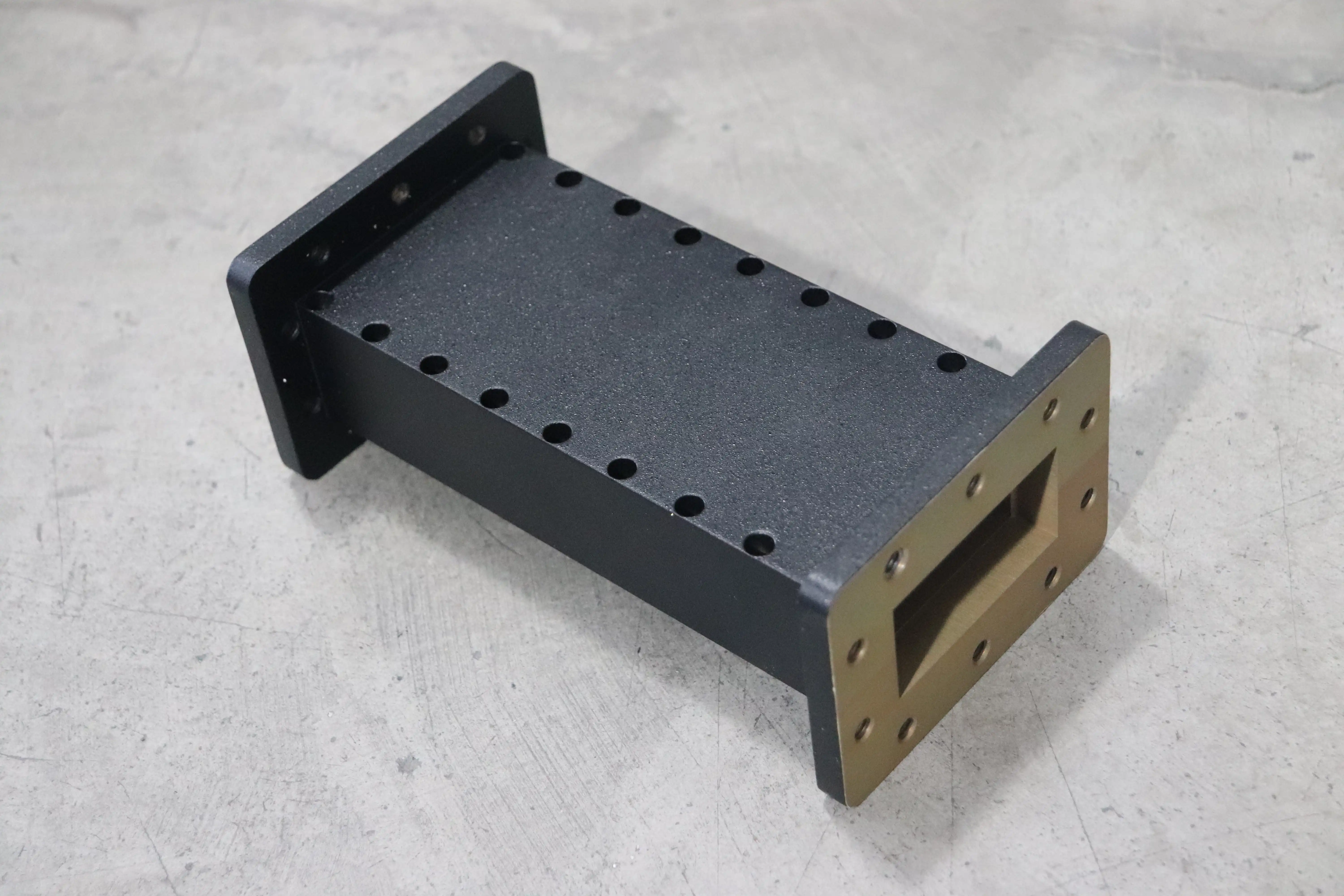
When high power handling and low loss are needed, waveguide low-pass filter designs with optimized corrugations work better than coaxial or lumped-element filters. The insertion loss of a corrugated waveguide filter designed for 5 kilowatts CW operation is about 0.08 dB. On the other hand, the loss of an identical coaxial cavity filter handling the same amount of power might be 0.3 dB while taking up more space. This performance gap gets even bigger at millimeter wave frequencies, where waveguide sizes get smaller while coaxial parts have to deal with higher wire losses and multipactor risks. Defense companies that are buying parts for phased array radar systems really like the benefits of waveguide topologies because the corrugation depth can be changed to block certain frequencies that could interfere with the main signal transfer.
Practical Applications and Performance Case Studies
Satellite Communication Ground Terminals
Uplink paths from ground stations are used for demanding tasks where optimizing corrugation has a direct effect on operating efficiency. For a recent rollout using Ku-band earth terminals, filters that could block second harmonic sounds below -65 dBc were needed to keep them from interfering with satellite transponders that were nearby. By using corrugations with a depth of 8.2 millimeters in a five-section design, the filters were able to block 68 dB of the second harmonic while keeping an insertion loss of 0.09 dB across the 14.0–14.5 GHz uplink band. The user was able to meet the standards of the International Telecommunication Union for spectral masks without having to add any more filtering stages. This made the system simpler and reduced signal path losses.
High-Power Radar Transmitter Protection
For air traffic control radars that work in the S-band, controlling spurious emissions is very important so they don't mess up the aerial transmission bands. In a case involving updating the main monitoring radar, filters had to be able to handle 25 kilowatts of peak power and block harmonics by at least 60 decibels. Corrugations with a depth of 12 millimeters and smooth internal changes to keep the voltage from dropping worked perfectly in high-power tests at 30 kilowatts peak, without any arcing. After 18 months of use in the field, data showed that the device continued to work properly, with no changes in its rejection properties, even though it was constantly exposed to temperatures ranging from -20°C to +55°C.
Industrial Microwave Heating Systems
Commercial microwave applicators used in materials handling create a lot of harmonic content that needs to be kept in check to follow FCC Part 18 rules. A company that makes continuous belt dryers needed screens for magnetron sources that put out 75 kilowatts of power at 2.45 GHz. Custom waveguide low-pass filters with a corrugation depth of 10.5 millimeters were able to block 62 dB of noise at 4.9 GHz (second harmonic) while constantly handling full maximum power. After the installation, tests for electromagnetic interference showed that the limits for radiated emissions were met. This proved that the estimates for corrugation depth were correct, taking into account the specific impedance of the customer's waveguide distribution network.
Procurement Considerations for Waveguide Low Pass Filters
Evaluating Technical Specifications and Datasheets
When procurement engineers look at manufacturer datasheets, they should look closely at factors linked to corrugation that go beyond basic frequency specs. Some important things to look at when judging are the corrugation depth limit (which is usually set at ±0.013 millimeters for precision filters), the quality of the surface finish, which affects how much power it can handle, and the plating specs, which affect how stable it will be in the long term. Instead of just taking generic performance curves, ask for specific mechanical drawings that show corrugation profiles. Instead of just using modeling results, reputable providers give measured S-parameter data for each production unit. This shows the real insertion loss and return loss over certain frequency ranges.
Assessing Manufacturer Reliability and Customization Capability
Because making a waveguide low-pass filter is so complicated, you need providers who have a track record of precise cutting and strict process controls. Check to see if possible partners are ISO 9001 certified, have in-house test facilities with vector network analyzers that cover your frequency range, and are ready to give you first-article inspection reports. Customization needs, like non-standard flange types, covering for outdoor use, or pressurization options, have a direct effect on wait times and minimum order amounts. Our 24-meter anechoic room and measurement skills up to 110 GHz at Advanced Microwave Technologies Co., Ltd., let us fully test custom filter designs before committing to large-scale production.
Pricing Factors and Supply Chain Management
The level of complexity in the corrugation has a big effect on unit costs. Designs with deeper and tighter tolerances fetch higher prices because they take longer to machine and have higher scrap rates. Lead times for custom waveguide filters are usually between 8 and 12 weeks, but for urgent development projects, sample numbers can be sped up to 4 to 6 weeks. Make sure you agree on clear terms for the processes for checking the depth of the corrugation. For example, some makers charge extra for detailed dimensional inspection reports that use coordinate measuring tools. Set up clear lines of communication with engineering contacts, not just sales reps, to answer technical questions about how to optimize corrugation for your unique application needs.
Future Trends and Innovations in Waveguide Low Pass Filter Corrugation
Advanced Manufacturing Technologies Enabling Precision Control
Additive manufacturing methods, especially direct metal laser sintering, are becoming more popular as ways to make waveguide low-pass filters instead of the more standard CNC cutting. These techniques make it possible to make complex corrugation profiles that can't be made with traditional subtractive methods. For example, they can make variable-depth corrugations that taper along the length of the filter or three-dimensional lattice structures that improve the rejection bandwidth. At the moment, the quality of the surface finish means that additively made filters can only be used for lower frequencies below 20 GHz. However, improvements in post-processing methods should make them useful in millimeter-wave bands within the next three to five years.
Material Science Innovations Driving Performance Gains
The goal of research into low-loss dielectric films that are put on curved surfaces is to lower insertion loss even more while keeping rejection levels high. Nano-structured surface treatments are being looked into because they might be able to cut down on skin effect losses by 15 to 20 percent compared to regular silver plating. This is especially helpful in millimeter-wave filters where conductor losses are the main cause of total insertion loss. These improvements will make it possible for next-generation satellite communication systems that use Ka-band and V-band frequencies to do better than those that could only work at lower microwave frequencies before.
Market Evolution in 5G and Aerospace Applications
As 5G millimeter-wave infrastructure is put in place, the need for small, high-performance filters with carefully controlled corrugation features is growing faster. For base station uses that need filters at 28 GHz and 39 GHz bands, rejection requirements are stricter than for standard microwave systems. This has led to new ways of designing corrugations. In the same way, the growing commercial space industry needs light waveguide parts for things like low-Earth-orbit satellite systems for high-speed internet. Improving corrugation directly affects payload mass costs in this area. Procurement teams should keep an eye on how industry standards change to accommodate these new uses, and they should give priority to sellers who are actively investing in research to meet future needs.
Conclusion
Waveguide low-pass filters' rejection performance is largely determined by the depth of the corrugations, which also has a direct impact on stopband attenuation, cutoff features, and power handling capacity. Engineers can make filters that meet strict requirements for satellite communications, radar systems, and industrial microwave applications by finding the best balance between rejection level, insertion loss, and physical size by optimizing this important parameter in the right way. Understanding the connection between corrugation geometry and electrical performance helps procurement decision-makers choose the best supplier and create detailed specifications. This makes sure that systems that are deployed meet performance requirements and remain reliable over time, even when they are put through heavy operational loads.
FAQ
1. How does corrugation depth specifically affect rejection slope steepness?
When corrugations get deeper, they make impedance discontinuities that are stronger. These discontinuities raise reflection coefficients for frequencies that are outside of the band, which makes the change from passband to stopband sharper. A filter with 10-millimeter corrugations can usually reject 40 dB within 1.5 times the cutoff frequency. A filter with 6-millimeter corrugations, on the other hand, might need 2.0 times the cutoff to reach the same amount of rejection.
2. Can corrugation depth be customized for specific harmonic frequencies?
Of course. Engineers use electromagnetic simulation tools that model corrugation resonances to figure out the best depth based on the goal rejection frequencies. Custom designs that aim to block second harmonics use different depth profiles than filters that are made to block third harmonics. This lets you make solutions that work with the way your emitter works.
3. What tolerance variations in corrugation depth are acceptable without degrading performance?
For precise uses, depth limits of within ±0.013 millimeters are usually needed to keep the cutoff frequency stable within ±50 MHz at X-band frequencies. For lower-frequency uses, where wavelength scaling makes changes in dimensions less noticeable, looser limits may be fine. First-article measurement inspection records should be used to check the manufacturing process's ability.
Partner with ADM for Precision Waveguide Low Pass Filter Solutions
The designed waveguide low-pass filters from Advanced Microwave Technologies Co., Ltd. meet your exact rejection requirements through corrugation depth optimization. Our skilled RF engineering team works directly with procurement managers to create unique filter designs that meet the tough needs of satellite communication, radar, and high-power microwave systems. We are a reliable waveguide low-pass filter manufacturer for defense contractors, aerospace integrators, and telecommunications system builders because our manufacturing processes are ISO 9001 certified, we can test in-house up to 110 GHz, and we offer full customization services backed by over 20 years of production experience. Email craig@admicrowave.com to talk about your application needs, look over full technical datasheets, and learn more about how our precision corrugation control gives you measurable performance benefits with short lead times and a choice of minimum order numbers.
References
1. Marcuvitz, Nathan. Waveguide Handbook: Corrugated Structures and Filter Design. Institution of Engineering and Technology, 2019.
2. Ragan, Gerald L. Microwave Transmission Circuits: Theory and Applications of Corrugated Waveguides. Dover Publications, 2020.
3. Chen, Wei-Kai. Theory and Design of Microwave Filters: Low Pass Rejection Mechanisms. Cambridge University Press, 2021.
4. Collin, Robert E. Foundations for Microwave Engineering: Waveguide Filter Topologies and Corrugation Analysis. IEEE Press, 2018.
5. Rhodes, James D. RF and Microwave Passive Component Design: Advanced Corrugated Filter Structures. Artech House, 2022.
6. Levy, Ralph and Snyder, Richard V. Advances in Waveguide Filter Design: Corrugation Optimization Techniques for Enhanced Rejection. John Wiley & Sons, 2023.