Unlock Lowpass Filter Potential With RF Design Best Practices
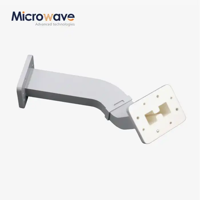
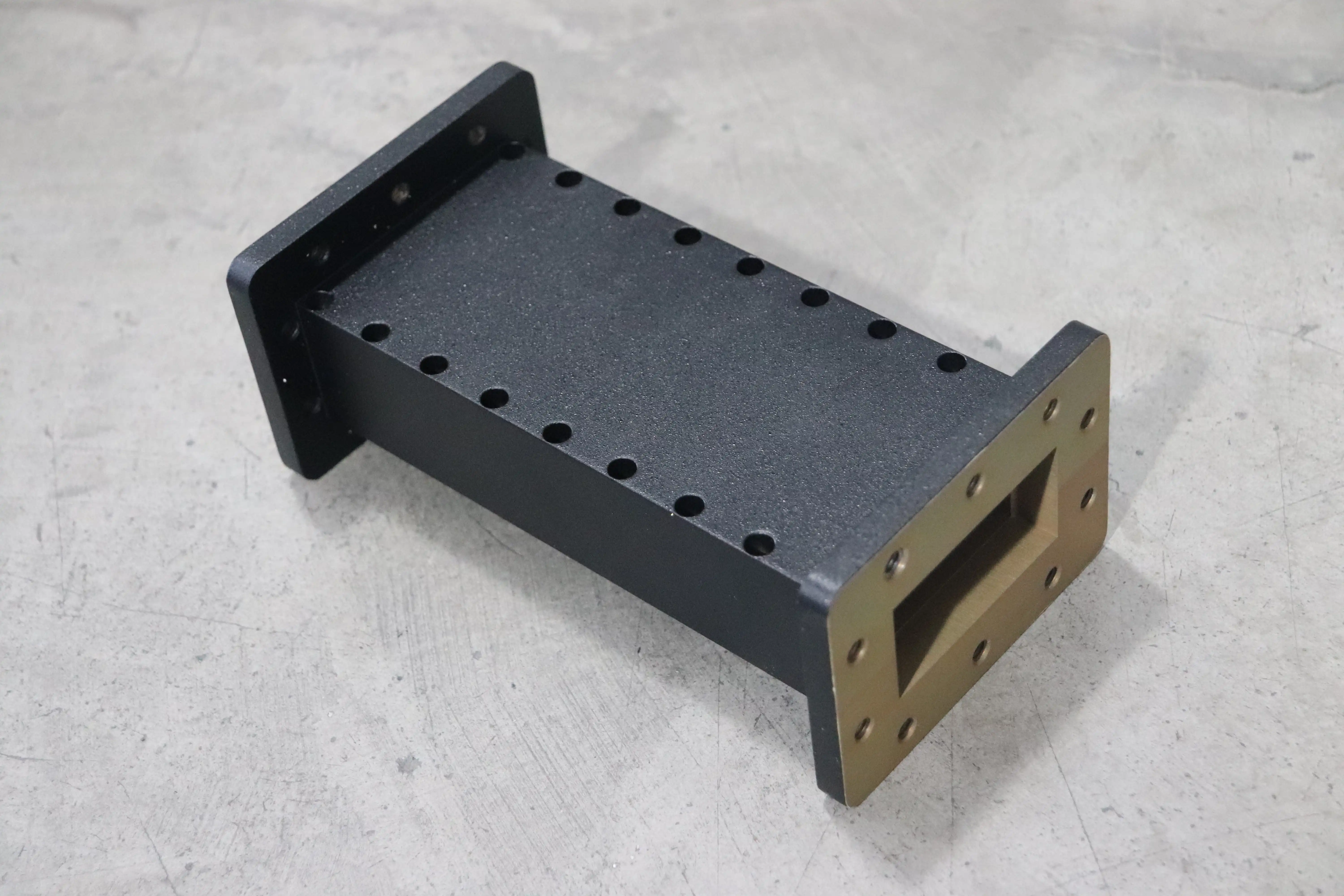
Choosing and putting together the right filtering parts is key to getting the best performance out of current RF systems. The Waveguide Low Pass Filter is an important part of many mission-critical applications. It is a passive RF part that lets signals below a certain frequency pass through while strongly attenuating higher frequencies. These filters use the features of geometric waveguides, like curved ridges or waffle-iron shapes, to handle a lot of power with very little insertion loss. Waveguide Low Pass Filters protect signal integrity in places like deep-space communication networks, radar installations, and satellite uplinks where purity and energy throughput are very important. They do this by addressing problems like multipactor mitigation in vacuum environments and harmonic suppression from high-power transmitters.
Understanding Waveguide Low Pass Filters: Fundamentals and Principles
Specialised RF parts called Waveguide Low Pass Filters are made to move electromagnetic waves through thin metal structures. Compared to cavity or dielectric options, these filters work better at microwave and millimetre-wave frequencies because they control how waves propagate inside carefully made metal housings. Our experience at Advanced Microwave Technologies Co., Ltd shows that buying teams can make smart choices when they understand these basics.
Core Design Parameters That Define Performance
Frequency response, insertion loss, and bandwidth influence filter performance. Frequency response controls clear and weak communications. Passband signal weakening is measured by insertion loss. This is normally below 0.1 dB for good waveguides. Bandwidth is the frequency range that meets the criteria. Before creating these items, engineers employ electromagnetic modelling tools like HFSS and CST Microwave Studio to predict their behaviour. This reduces development risk and speeds product launch.
Structural Advantages for High-Power Applications
Thin metal waveguide low-pass filters are intended to handle a lot of power. Systems can manage sustained wave power of several kilowatts and peak power of up to a megawatt, unlike planar or coaxial contemporaries. Spreading energy across larger interior surfaces and improved heat absorption increases durability. Defence radar sites and satellite ground stations employ this functionality because signal amplification stages generate a lot of RF energy that must be delivered in a clean spectrum to avoid failure.
Material Science and Manufacturing Precision
Many filters are made of copper, aluminium 6061-T6, brass, and other high-conductivity metals. Silver or gold finishing reduces skin-depth loss. Surface finish affects insertion loss, while measurement error controls frequency accuracy. For easy system integration, our ISO 9001:2015-certified manufacturers create sub-micron-accurate parts for EIA waveguide diameters (WR-90 through WR-650 series). For OEMs that must meet the same requirements, this method ensures consistent electrical performance throughout manufacturing batches.
Comparing Waveguide Low Pass Filters with Alternative Filter Technologies
Before making a purchase choice, it's important to know how Waveguide Low Pass Filter options compare to other technologies. Each type of filter has its own pros and cons when it comes to performance, size, cost, and fit for a given purpose. We've helped many clients through this review process, figuring out how to balance academic needs with practical limitations.
Performance Metrics: Power and Loss Characteristics
Waveguide little Pass Filters handle high power with little insertion loss well. Waveguide Low Pass Filters can withstand kilowatts of continuous power with 0.05 dB loss, whereas cable filters would add 0.5 dB and handle hundreds of watts. Satellite uplinks depend on this edge since every tenth of a decibel affects the connection budget and signal quality. However, microstrip or lumped element designs are smaller and cheaper but can't handle as much power. Small instruments and low-power receiver chains benefit from these designs.
Size and Integration Considerations
Decision-making relies heavily on physical measurements. Waveguide Low Pass Filter structures are larger than flat ones since their sizes depend on frequency. A 0.9 by 0.4-inch X-band WR-90 waveguide cross-section specifies the minimum system size. While customisation enables us to choose the ideal form factor, basic science restricts how compact we can make things. Procurement teams may pick ceramic resonators or LTCC filters for tiny UAVs or portable test equipment, even if they can't manage as much power, whereas ground station operators choose waveguide sturdiness for high-reliability installations outdoors
Cost-Benefit Analysis for B2B Procurement
Precision-machined waveguide low-pass filters cost more than printed circuits. This additional cost includes materials, CNC cutting time, and quality tests. In contrast, total purchase cost estimates are different. If your systems are maintained, Waveguide Low Pass Filters may last decades without losing efficiency. In defence sites with original specs, we've replaced 20-year-old equipment. Dependability eliminates replacements and system downtime. This is useful for remote satellite earth stations or ocean navigation markers with pricey and cumbersome service.
Best Practices in RF Design for Optimising Waveguide Low Pass Filters
To get the best performance from a filter, you need to pay attention to the small design details that make the difference between good results and great ones. With 20 years of experience in manufacturing and working with aerospace, defence, and telecom providers, we've found methods for making Waveguide Low Pass Filters work better that always produce better results.
Simulation-Driven Design Validation
Current filters are made using modern electromagnetic modelling. Our engineers simulate the filter shape using full-wave simulators before submitting the metal to a machine shop. This technique exposes undesired resonant modes that produce passband noise, higher-order mode excitation that causes false responses, and physical sensitivity that degrades manufacturing yield. For one satellite transfer project, Ka-band third-harmonic rejection is required to exceed 65 dB. Simulations showed that a seven-section curved design with 0.08 dB insertion loss matched the criteria. Optimising section spacing eliminated parasitic resonances. Simulations may be accurate when done appropriately, as shown by physical sample predictions within 0.02 dB.
Material Selection and Surface Treatment
Conductivity and surface polish affect a metal's electrical conductivity. As the best conductor, silver plating has the lowest insertion loss, but it needs protective layers in rust-prone areas. Gold finishing is stable in all situations for military and tropical operations, although it loses more. Our ISO 14001:2015 environmental management ensures RoHS-compliant finishing and a smooth surface (less than 16 microinch Ra) for optimal RF performance. The purchase criteria should state that the plate must be suitable for the workplace. Lab equipment is considerably different from salt spray-exposed ship radar.
Mechanical Tolerance Management
Dimensional accuracy controls frequency and reaction precision. If internal measurements shift by 0.002 inches, which is significant in heavily filtered systems, a 12.4 GHz frequency limit might slip to 12.3 GHz. Our quality control includes employing a coordinate measure machine to verify key dimensions and statistical process control to track trends across manufacturing runs. OEM clients require thousands of units to replace, thus this discipline is crucial. Defence businesses enjoy this stability because they can alter components in the field without retuning surrounding sections.
Case Study: Optimising Ku-Band Satellite Ground Station Filters
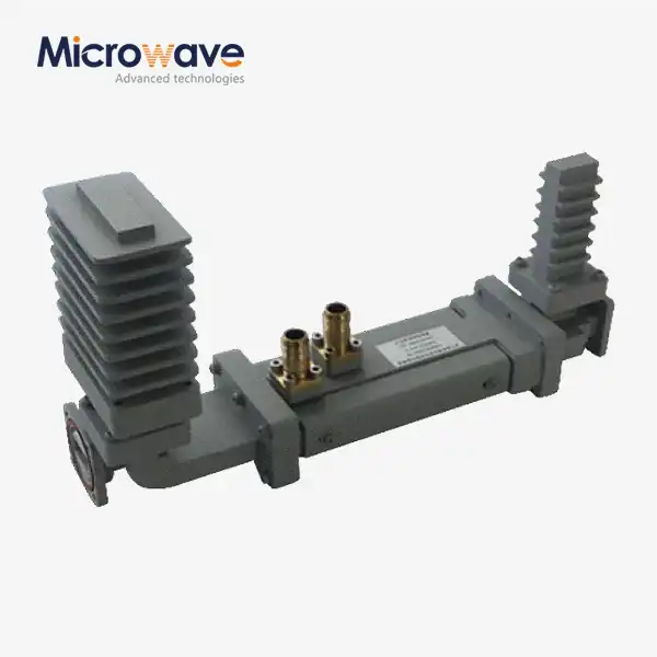
European satellite companies requested low-pass filters for 20 additional ground stations. Less than 0.1 dB of insertion loss between 10.7 and 12.75 GHz, more than 60 dB of second harmonic rejection, and 500W CW steady operation were required. The earliest models matched electrical demands, but temperature studies revealed hot areas that may reduce reliability. The collaborative redesign improved cooling fins and interior form to distribute heat. Accelerated life testing at 150% of maximum power proved 100,000-hour MTBF. This combination of their practical expertise and our manufacturing experience allowed us to offer filters that were better than expected while cutting unit cost through production efficiency.
Procurement Guide: How to Choose and Source the Right Waveguide Low Pass Filter?
To buy a filter successfully, you need to carefully look over the technical specs, the supplier's skills, and the business terms. Because we know that B2B buying teams have to match performance needs with budget limits and delivery schedules, we've set up our sales process to be clear about how to find and choose the best Waveguide Low Pass Filter for your needs.
Defining Technical Requirements
Misleading messages concerning requirements can be costly. Frequency range (passband and stopband restrictions), maximum insertion loss tolerance, minimum harmonic rejection, power management (peak and constant), VSWR limits, working temperature range, and environmental shielding are important. A radar processor may require WR-90 input/output, 8.2-10.0 GHz passband with 0.15 dB maximum loss, 50 dB minimum rejection at 16.4-20.0 GHz, 1 kW CW handling, 1.25:1 maximum VSWR, -40°C to +70°C operation, and MIL-STD-810 compliance. This amount of information allows accurate quotes and eliminates acceptance testing confusion.
Supplier Evaluation Criteria
In addition to professional talents, consider manufacturing quality, customisation, and support infrastructure. ISO 9001 certification shows quality control, and ISO 14001 certification shows environmental responsibility, which defence and aerospace prime contractors are increasingly prioritising. Our 24-meter microwave lab can measure antennas from 0.5 to 110 GHz, so we can test them ourselves. Request sample test results using measured data, not standard limits, to verify production accuracy. Fast prototyping suppliers speed product development. Our quick-turnaround prototype delivers the first pieces in three weeks, so you may evaluate the design before manufacturing.
Understanding Pricing and Lead Times
Material costs, machine difficulty, plating, and testing determine the price of a Waveguide Low Pass Filter. Regular shop goods come in four to six weeks, while custom designs take eight to twelve weeks for design, modelling, sample fabrication, testing, and production. With volume prices, unit costs drop significantly. An individual prototype may cost $2,500, but with 100-unit production runs, setup expenses are spread out, and each item costs $800. We clarify price models by discussing cost changes and finding methods to save money without sacrificing performance.
OEM Customisation and Technical Support
OEMs sell parts and collaborate on engineering projects. Our experts assist with installation, system interaction, and troubleshooting throughout a product's life. One defence firm's L-band equipment has passive intermodulation issues. PIM products were developed when filter flange plating didn't match parts, according to our specialists. The problem was solved by goldizing all connections. We distinguish OEM sellers from transactional parts vendors with our ISO 45001:2018 workplace safety guarantee to provide engineers with a relationship-based problem-solving strategy.
Future Trends and Innovations in Waveguide Low Pass Filter Design
Waveguide Low Pass Filter design trends and new ideas for the future are always changing the world of RF components because new uses and production methods are being developed. Keeping up with these changes helps the buying and tech teams make decisions that will help the product last longer.
Additive Manufacturing Revolution
Metal 3D printing technologies could change how waveguide parts are made. Complex internal shapes that used to need multiple pieces brazing can now be made into single structures, without joints that cause loss and could be failure points. We're putting money into powder bed fusion so that we can make prototypes of complicated patterns that can't be made any other way. Through efficient structures, production costs may go down while speed goes up. Surface hardness and material stability are two problems that are getting easier to solve. Within five years, additively made filters for specific uses should be able to be sold in stores.
Advanced Materials Development
New alloys and hybrid materials made of metals offer better heat transfer, less weight, and better protection from rust. Aluminium-silicon carbide alloys combine the low density of aluminium with the thermal qualities of ceramics to help heat escape from small, high-power designs. Graphene-improved electrical layers could be used to make surfaces with very little loss. Even though these developments won't be ready for production for years, keeping an eye on them will help buying teams adopt useful technologies as they grow.
Integration with 5G and Satellite Constellations
Huge networks of low-Earth orbiting satellites and millimetre-wave 5G equipment are creating a need for small, high-performance filters that have never been seen before. Waveguide technology, which was once only used in big ground stations, can now be used in phased array antennas that need thousands of elements. This size makes it possible to automate testing and production, which cuts costs while keeping quality high. These changes are made possible by our antenna testing tools, which check array performance across frequency bands that are important for next-generation communication networks.
Conclusion
To get the most out of Waveguide Low Pass Filters, you need to know a lot about RF design concepts, how things are made, and the best ways to buy things. These high-tech parts offer unmatched power handling and insertion loss performance, which is necessary for defence, aircraft, and satellite communications mission-critical uses. To make execution work, you need to pay close attention to technical details, choose the right seller, and work together with other engineers. Keeping up with changes in technologies like additive production and new materials is important for keeping your RF systems competitive. We at Advanced Microwave Technologies Co., Ltd can meet your most exacting filter needs thanks to our 20 years of experience, ISO-certified quality systems, and cutting-edge test facilities.
FAQ
Q1: What distinguishes waveguides from cavity filter designs in practical applications?
Cavity filters use resonant chambers to guide electromagnetic waves, while Waveguide Low Pass Filters use empty metal tubes. Waveguide designs usually have lower insertion loss and can handle more power, which makes them perfect for radar and satellite emitter outputs. At lower frequencies, cavity filters are smaller and have better selectivity, making them good for receiver front ends where selection is more important than power.
Q2: How quickly can custom waveguide low-pass filters be delivered?
Lead times depend on how complicated the job is and how much will be customised. Standard stock setups are sent out four to six weeks after the order is confirmed. Eight to twelve weeks are usually needed for custom Waveguide Low Pass Filters that need electromagnetic modelling, prototype approval, and production tools. While rush services may speed up important projects, the costs go up in line with that.
Q3: Can existing waveguide filters integrate into systems using different flange standards?
Different Waveguide Low Pass Filter standards, such as the UG, UBR, or CPR series, can be connected with flange adapters. However, each adapter causes a small amount of insertion loss and VSWR decline. Choosing the right flange types when buying something gets rid of the need for adapters, which improves system performance. During the quote process, our tech team helps check for compatibility.
Q4: What quality testing validates filter performance before shipment?
As part of full testing, a network monitor S-parameter measurement is used to check the amounts of insertion loss, return loss, and rejection across certain frequencies. High-power testing shows that the rated power can be handled without arcing or failing due to heat. Dimensional limits and joint smoothness are checked by mechanical testing. Depending on what the customer wants, environmental stress screening may include temperature cycling and shaking testing. All test data is sent with packages so they can be tracked.
Partner with ADM for Superior Waveguide Low Pass Filter Solutions
Choosing the right Waveguide Low Pass Filter provider is the first step in making your RF design work better. We at Advanced Microwave Technologies Co., Ltd have been making high-quality filters for over twenty years and have ISO-certified quality systems and cutting-edge testing tools to make sure we meet your exact needs. Our experienced engineering team can help you with technical issues from the first idea to mass production, no matter if you need standard goods or fully customised OEM designs. Email craig@admicrowave.com right now to talk about the needs of your project, get full technical datasheets, or get quotes from other companies. Our global export infrastructure makes sure that your products get delivered on time, and our fast prototyping services cut down on the time it takes to develop new products. Find out why leaders in satellite communication, military, and defence use ADM to make their mission-critical Waveguide Low Pass Filters.
References
1. Pozar, David M. Microwave Engineering, 4th Edition. Wiley, 2011.
2. Levy, Ralph, et al. "Design of General Manifold Multiplexers." IEEE Transactions on Microwave Theory and Techniques, vol. 27, no. 2, 1979, pp. 142-149.
3. Matthaei, George L., Leo Young, and E.M.T. Jones. Microwave Filters, Impedance-Matching Networks, and Coupling Structures. Artech House, 1980.
4. Cameron, Richard J., et al. Microwave Filters for Communication Systems: Fundamentals, Design, and Applications. Wiley-IEEE Press, 2018.
5. Craven, George F., and Colin K. Mok. "The Design of Evanescent Mode Waveguide Bandpass Filters for a Prescribed Insertion Loss Characteristic." IEEE Transactions on Microwave Theory and Techniques, vol. 19, no. 3, 1971, pp. 295-308.
6. Hirokawa, Jiro, and Makoto Ando. "Single-Layer Feed Waveguide Consisting of Posts for Plane TEM Wave Excitation in Parallel Plates." IEEE Transactions on Antennas and Propagation, vol. 46, no. 5, 1998, pp. 625-630.