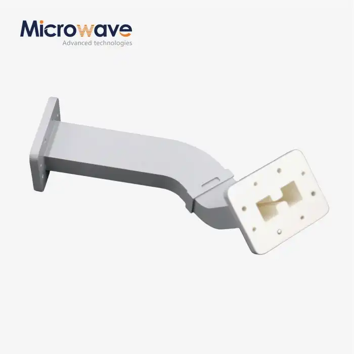
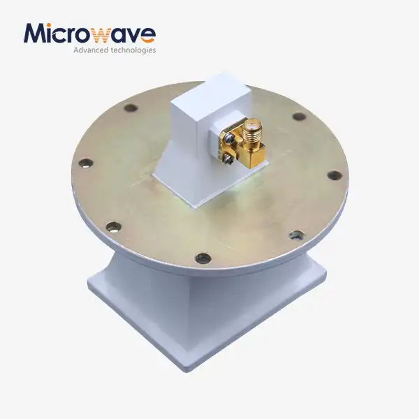
Waveguide Tube Dimensions and Power Handling
For purchase engineers and expert buyers looking for RF parts for mission-critical uses, it's important to know how waveguide tube lengths and power handling skills work together. A waveguide tube is a carefully designed hollow metal structure that sends electromagnetic waves through air or a special gas instead of solid dielectrics. This makes it work better at microwave frequencies. What the component's working frequency range is and how much power it can safely send without breaking down or overheating are directly related to its width, height, wall thickness, and length. At Advanced Microwave Technologies Co., Ltd., we've been making waveguide assemblies for more than 20 years. During that time, we've seen how choosing the right physical specs can make radar, satellite communications, and flight systems more reliable.
Understanding Waveguide Tube Dimensions
The way waveguide tubes work electrically across frequency bands and working conditions is based on their dimensional properties. To choose parts that meet system needs without adding too much cost, procurement teams need to know how shape affects mode transmission, frequency response, and material integrity.
Standard Classification Systems: WR Series and Beyond
WR (Waveguide Rectangular) names typical sizes that match frequency ranges. Internally 0.900 inches by 0.400 inches, the WR-90 is utilised in X-band (8.2–12.4 GHz). High-frequency Ku-band transmissions flow to WR-75, low-frequency C-band to WR-284. These standards enable producers and system developers to collaborate, making buying easier.
Military and aviation specs follow MIL-DTL-85/3 standards, which tighten dimensions and material requirements. Our production procedures are ISO 9001:2008-approved and maintain ±0.001 inch restrictions. This ensures electrical performance is consistent between batches. Buyers should specify the cutoff frequency, flange type (UG, CPR, or custom), and assembly circumstances when ordering non-WR sizes.
Rectangular versus Circular Cross-Sections
Rectangular waveguides are most used in industry because they maintain polarisation and TE mode transmission. The electric field parallels the wide wall in the primary mode. This creates consistent radiation patterns for phased array antennas and high-precision radar.
Circular waveguides are used in rotating joints and feed horns for rotational symmetry. However, mode rotation can cause the polarisation plane to shift during gearbox without internal grooves or dielectric plugs. Thus, rectangular designs are superior for ground station uplinks and defence radar sites where polarisation stability affects signal quality and target separation.
Wall Thickness and Material Selection Impact
Wall width impacts strength and electrical conductivity. Depending on frequency and application, brass or copper-plated metal walls are 0.040 to 0.125 inches thick. Thicker walls cool high-power continuous wave transmissions, but thinner barriers lighten flying systems.
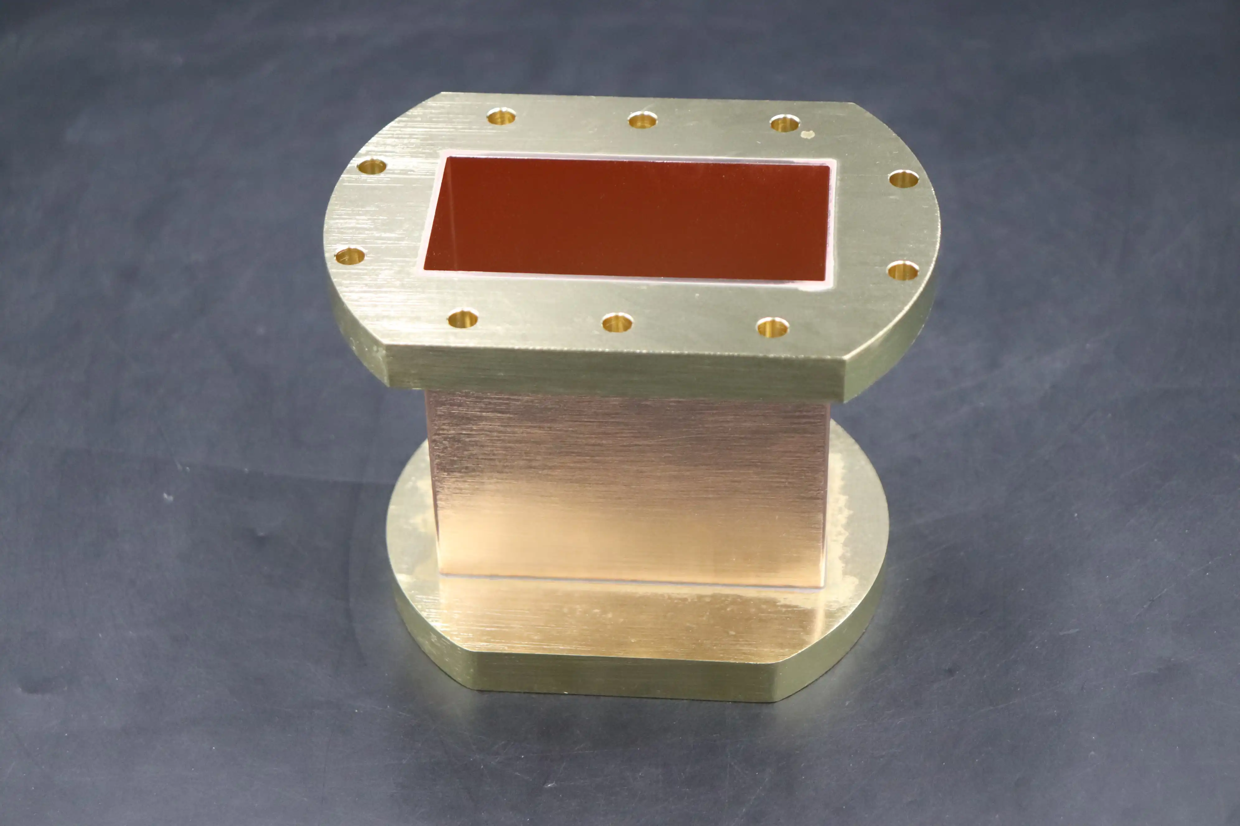
Material selection balances cost, weight, and conductivity. For satellite ground stations with weak receive signals, oxygen-free copper offers the lowest ohmic loss but is heavy and costly. UAV and aeroplane systems benefit from aluminium alloys' strength for their low weight. Their conductivity is 60% of copper's. Plated aluminium waveguides with silver or gold enhance surface conductivity while maintaining weight. Metal thickness, generally between 0.0002 and 0.0005 inches, must be controlled to prevent breakage when temperatures range from -55°C to +85°C.
Relationships between cutoff frequency and operating bandwidth
The width of rectangular guides impacts their cutoff frequency, which is the lowest frequency a waveguide can transport. The equation fc = c/(2a), where c is the speed of light and a is the wide dimension, shows this vital aspect. With a thickness of 0.900 inches, WR-90 may be utilised from 8.2 to 12.4 GHz with a minimum frequency approaching 6.56 GHz.
At least 25% above the cutoff frequency, single-mode transmission, and low dispersion are ensured. The procurement requirements should provide the working frequency range and VSWR throughout that band. When VSWR is 1.15:1 instead of 1.30:1, dimensions and internal surface polish must be better controlled. This raises manufacturing costs and wait times. Our engineering staff helps consumers balance performance and pricing with early technical guidance.
Power Handling Capabilities of Waveguide Tubes
The waveguide tube's power handling ability tells us if it can handle high-energy transfers without arcing, burning, or signal loss. These limits are set by the size, material, and treatment of the surface. They are very different for pulsed radar and continuous wave uses.
Electromagnetic Breakdown and Voltage Limits
Arcing occurs when the electric field intensity exceeds the waveguide's air dielectric strength, which at sea level is 30 kV/cm. Electric forces extend over larger cross-sectional regions, raising the breaking threshold. Due to its larger internal capacity, the WR-284 can withstand greater peak power than the WR-28, yet both perform well in their respective frequency ranges.
Pressurising with dry nitrogen or air improves breakdown voltage by 30–50%, increasing power capacity without increasing size. Weather radar and high-power receivers employ 15–30 PSI pressurised units. Pressure windows and sealed flanges are difficult and expensive, but they're required when the space can't accommodate larger waveguides. We manufacture pressure systems that fulfil aerospace and military standards, with helium leak rates below 1×10⁻cc/sec.
Thermal Management and Dissipation Strategies
When using continuous waves, the waveguide walls undergo consistent I²R losses. Heat stress weakens structural and electrical performance. Heat loss depends on wall thickness and heat conductivity. Copper conducts heat better than aluminium (401 W/m·K vs. 237 W/m·K), making it ideal for high-duty-cycle emitters in satellite earth stations.
Thermal expansion differences between waveguide sections and installed hardware might stress and misalign the hardware. Match materials with different thermal expansion coefficients while connecting them. For instance, aluminium waveguide brass flanges must be properly engineered to stay put when temperatures fluctuate. In building, finite element analysis identifies hot spots and significant mechanical stress. We can create the greatest cooling fins or forced-air routes for tough conditions.
Surface Finish and Coating Effects on Power Performance
Internal surface hardness affects ohmic loss and power handling. Electropolished copper surfaces with Ra values below 0.5 microns prevent current congestion and hot spots. Chemical cleaning removes oxides and other contaminants that increase flange joint contact resistance.
Silver coating enhances the waveguide tube gearbox and resists corrosion better than copper, extending life in damp and salty environments. For systems like satellite ground infrastructure that must last decades without maintenance, gold coating is optimal for rust prevention. In our quality control labs, tape testing and X-ray fluorescence checks ensure plating sticks properly and are the same width across production runs.
Real-World Application Examples
Megawatt-class long-range radars require rectangular waveguides WR-2300 or larger with walls thicker than 0.125 inches. Several microsecond pulses are produced by these devices at a frequency near 1.3 GHz. They require high peak power and heat management.
Satellite ground stations employ WR-75 and WR-90 equipment for Ku and X-band uplinks, which can handle kilowatt continuous wave transmissions. Internal pressurisation and forced air cooling maintain joints below 70°C during extended transmissions. Our unique earth station feed networks have rotor joints, polarisers, and transition sections in temperature-controlled housings. These networks exhibit insertion loss ≤ 0.15 dB at all bandwidths.
Waveguide Tube Dimension and Power Handling Comparison with Alternative Technologies
When you compare waveguides to coaxial cables and other transmission lines, you can see where each technology really shines. This helps buying teams find solutions that meet the needs of the application without being too specific or lowering performance.
Power Capacity and Loss Characteristics
Dielectric losses in coaxial lines get worse with frequency, so they can't be used for runs longer than a few meters above 18 GHz. At 10 GHz, a 10-meter length of high-quality coaxial wire loses 3–5 dB, but an identical WR-90 waveguide piece loses less than 0.3 dB. In satellite receive chains, where every tenth of a dB changes link margin and data flow, this tenfold difference is very important.
Peak power usage is even more different from one another. Normal coaxial lines that can handle 1 kW of power continuously at 10 GHz might be able to handle 10 kW of power at their peak in burst use. A similar waveguide tube can handle 100 kW of high power regularly, and compressed versions can handle megawatt amounts. This power level is needed for defence radar and electronic warfare systems to reach the required detection limits and blocking efficiency.
Size, Weight, and Installation Flexibility
Coaxial wires are easy to install because they can be bent, twisted, and run through tight areas. Rigid waveguide parts need to be precisely aligned and supported mechanically, which adds to the work and difficulty of planning for installation. Some route problems can be solved with flexible waveguide parts, but they are more expensive and have more insertion loss than solid ones.
For movable and flying systems below 6 GHz, coaxial wires are better because they are lighter. Above that point, waveguide assemblies can compete because system designers have to accept the mechanical trade-offs caused by cable loss costs. Unmanned aerial vehicles that fly at X-band are using more and more light metal waveguides with precisely polished flanges to cut down on both loss and aircraft weight.
Environmental Robustness and Signal Integrity
Waveguides completely block electromagnetic interference; outside signals can't get through the conductive walls, and signals inside the waveguides can't send signals outside. This natural separation stops cross-talk in places with a lot of radio waves, like on ships and in airport monitoring systems.
Shielding on coaxial cables gets less effective as they bend, as connectors get worse, and as the cables age. When moisture gets into broken jackets, it increases loss and can cause signal delays that happen from time to time. When the right corrosion-resistant surfaces and protected joints are selected, waveguide systems are better able to withstand damage from the environment. Our RoHS-compliant production methods and outdoor stress testing show that our products work well in a wide range of temperature, humidity, and pressure levels that are common in defence and aircraft applications.
Rectangular versus Circular Waveguide Trade-offs
Rectangular waveguides keep the orientation and support known mode structures. This makes designing radio feeds and putting the system together easier. When continuous rotation is needed, circular guides work well for rotary joints. For example, radar station mounts and satellite tracking pedestals depend on circular waveguide rotary joints to keep signal lines open when the parts move.
If you don't use careful filtering, circular waveguides can transmit more than one mode at the same time, which makes wideband designs harder. It is not necessary to add extra filtering parts when the geometry is rectangular because it automatically blocks higher-order modes over well-defined bandwidths. When making a procurement choice, these things should be weighed against the space limitations and hardware contact needs that are unique to each system design.
Procurement Considerations for Waveguide Tubes
To make sure that parts are delivered on time and meet strict performance and dependability standards, waveguide buyers must find a balance between technical requirements, the supplier's skills, and organisational issues.
Critical Specifications and Tolerances
Tolerances in dimensions have a direct effect on how well electricity works. As a general rule, buyers should ask for internal measurement limits of ±0.001 to ±0.003 inches, flange smoothness of within 0.002 inches, and joining surfaces that are perpendicular to each other. VSWR, insertion loss, and power handling uniformity across production lots are all based on these mechanical factors.
The finish on a material must be specified in terms of its conductivity, resistance to rust, and ability to stick to plating. Standards like MIL-DTL-15 for electroplating and ASTM B487 for electropolished copper should be used in procurement papers. To keep quality checks from getting confusing, testing and acceptance standards should be made clear. These should include things like eye inspection, physical proof, and RF performance measurements.
Custom versus Standard Solutions
Standard WR series parts have shorter lead times (often 2–4 weeks) and lower individual costs because the cost of the tools is spread out among many clients. Custom designs, like non-standard frequencies, unique flanges, and combined components, need engineering advice, multiple prototypes, and dedicated production sets, which adds to the time it takes to make the product, which is 8–12 weeks.
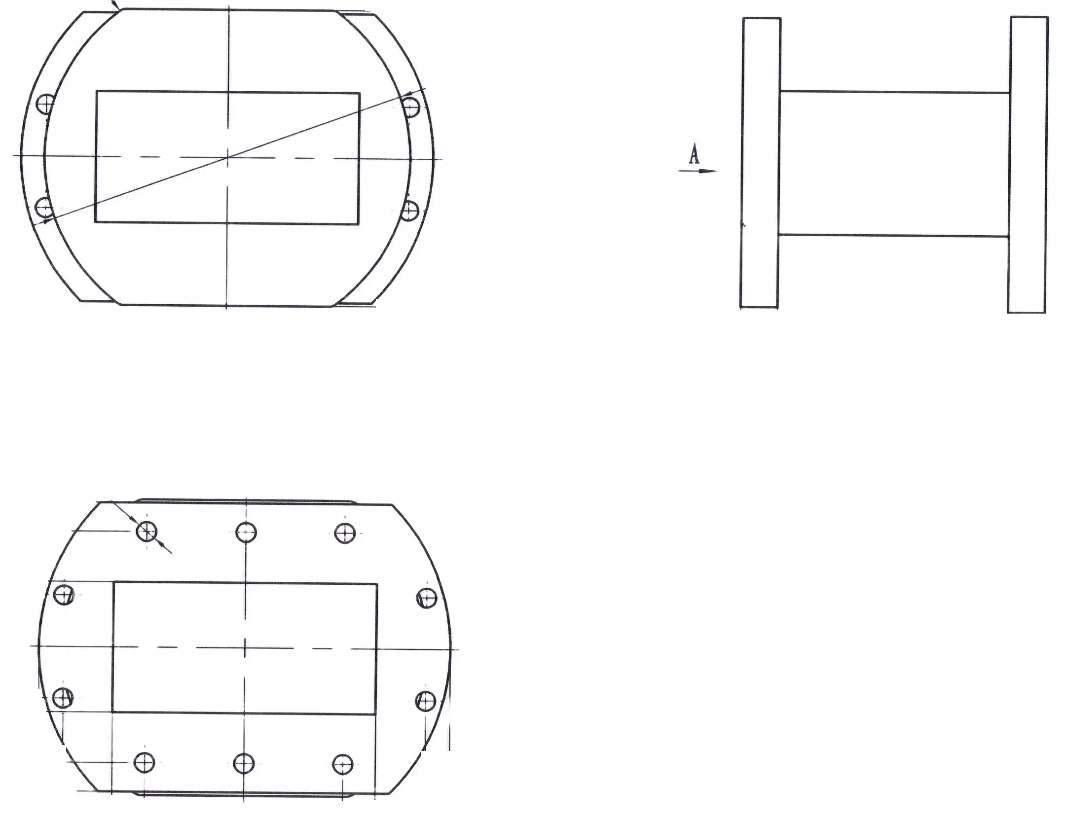
Custom solutions save money when standard ones make the system less reliable. Multiple flange joints are eliminated by a combined system that combines waveguide sections, bends, and transitions. This lowers insertion loss and possible failure points. Our OEM services help customers from the first idea to full-scale production. We use our more than 20 years of design knowledge to make sure that speed and ease of production are both optimised.
Supplier Selection and Quality Assurance
ISO 9001 approval means that quality management systems have been in place for a while, but it doesn't ensure professional skill or on-time delivery by itself. Facility checks, looking at measurement equipment calibration (we keep NIST-traceable calibration up to 110 GHz), production capacity, and past success with similar uses are all good ways for procurement teams to find out what a provider can do.
When making specifications and fixing problems with a waveguide tube, the level of customer help is important. Access to skilled RF engineers who can suggest the best setups, model performance, and solve integration problems is more valuable than just knowing how much a component costs. Within 24 hours of receiving an inquiry, our expert team provides modelling data, mechanical models, and application notes to speed up buying choices and lower project risks.
Supply Chain and Logistics Factors
Lead times change with the seasons and the availability of raw materials. For example, the price and supply of copper and specific metals change over time. Setting up outline deals with chosen providers keeps prices stable and guarantees production slots during times of high demand. For special parts, the minimum order quantity is usually between 10 and 50 units. Buyers should weigh the costs of keeping supplies against price drops per unit for bigger orders.
When you're doing global shipping, you need to pay attention to export rules. For example, waveguide systems used in defence may need export licenses, based on the specs and where the end users are located. We keep records of compliance and can speed up license applications because we have good ties with regulatory bodies. This keeps time-sensitive projects from being held up.
Conclusion
Waveguide tube size and power handling capacity go hand in hand. Geometry determines frequency response, while materials and manufacturing quality determine how reliable the tube is at high power levels. When making purchases, people have to decide between standard and unique options and balance performance needs with price and time limits. Our many years of experience at Advanced Microwave Technologies Co., Ltd show that for waveguide sourcing to work, buyers and suppliers need to be able to talk about technical details, making sure that requirements match up with the facts of the application and the production capabilities. Precision measurements and strict quality control are needed to make sure that mission-critical systems have the signal integrity and operating life they need. This is true for radar upgrade projects, satellite ground infrastructure, and research sites.
FAQ
Q1: What determines the cutoff frequency of a waveguide tube?
If you want to know what the cutoff frequency is for rectangular waveguides, you can use the formula fc = c/(2a), where c is the speed of light, and a is the width of the waveguide. When used below this frequency, the waveguide stops working quickly because it loses its power. To make sure single-mode transmission and good loss features, practical operation starts at least 25% above the cutoff.
Q2: How do I select the appropriate waveguide size for high-power applications?
Look at the working cadence, peak and normal power needs, and the surroundings. Larger cross-sections can handle more power, but they are harder to work with. Pressurisation increases power output without making the size bigger. Talk to the makers early on to go over temperature analysis and breakdown voltage calculations that are specific to your duty cycle and variation.
Q3: What causes signal loss in waveguide assemblies, and how can it be minimised?
Most of the ohmic losses come from the wall resistance and the lip contact resistance. Copper or metal that has been electropolished or silver-plated lowers the surface resistance. Low-resistance joints are made possible by precise plate alignment and controlled pressure specs. To keep reflection losses low and VSWR high across all working bandwidths, avoid physical dents, keep internal surfaces clean, and use bends that are properly designed.
Partner with a Trusted Waveguide Tube Manufacturer
Every waveguide tube job is handled by Advanced Microwave Technologies Co., Ltd, which has been making high-quality products and working as an engineer for more than 20 years. Our ISO-certified production facilities and 24-meter microwave lab allow full testing from 0.5 to 110 GHz, making sure that your parts meet all the requirements for size and power handling. We help acquisition teams by providing fast development, custom OEM solutions, and technical advice. Our decades of experience in the defence, aerospace, and satellite communication sectors back these up. Our engineers work with yours to make plans better, keep costs low and performance high, and meet deadlines, even for complicated, high-reliability projects. Email craig@admicrowave.com right away to talk about your waveguide tube needs, get full technical specs, or set up a meeting with one of our RF engineering experts. At admicrowave.com, you can look through our full product list and case studies to see how our waveguide solutions power important systems around the world.
References
1. Pozar, David M. Microwave Engineering, 4th Edition. Hoboken: John Wiley & Sons, 2012.
2. Skolnik, Merrill I. Radar Handbook, 3rd Edition. New York: McGraw-Hill Education, 2008.
3. Balanis, Constantine A. Antenna Theory: Analysis and Design, 4th Edition. Hoboken: John Wiley & Sons, 2016.
4. Saad, Theodore S. Microwave Engineers' Handbook, Volume 1. Dedham: Artech House, 1971.
5. Harvey, A. F. Microwave Engineering. London: Academic Press, 1963.
6. Collin, Robert E. Foundations for Microwave Engineering, 2nd Edition. New York: McGraw-Hill, 1992.