




Coaxial Cable Assembly
Coaxial Cable Assembly for RF Signal Transmission
Advanced Microwave Technologies Co., Ltd. (ADM) designs and manufactures Coaxial Cable Assembly products for RF signal transmission applications across telecommunications, aerospace, defense, and medical imaging. With over 20 years of microwave industry experience, ADM builds each assembly to maintain consistent 50Ω or 75Ω impedance, low insertion loss, and operating temperatures from -55°C to +200°C on PTFE-dielectric variants. Connector options include SMA, N-Type, BNC, TNC, 7/16 DIN, and 4.3-10.
What Is a Coaxial Cable Assembly?
A product is a ready-to-install RF transmission line: a coaxial cable terminated with specific connectors at one or both ends. Unlike bulk cable supplied on a reel, it arrives as a finished component, dimensionally matched between cable and connector, tested before shipment.
Field engineers encounter three recurring problems that factory-terminated assemblies address more reliably than field-spliced alternatives. The first is impedance discontinuity — any deviation from the nominal 50Ω or 75Ω value reflects power back toward the source, raising VSWR and reducing usable signal. The second is insertion loss over long cable runs, which accumulates with both distance and frequency. The third is EMI and RFI ingress in electrically dense environments, where shield continuity at the termination points is critical.
Factory termination controls each of these variables under repeatable conditions, producing consistent VSWR and phase stability across a production batch.
Construction Layers
Every assembly is built from four concentric layers. The choice of material in each layer affects attenuation, temperature range, flexibility, and environmental durability.
Layer | Material Options |
Inner Conductor | Copper or Copper-Clad Steel |
Dielectric Insulator | PTFE, PE, or Foam |
Outer Shield | Braided Copper and/or Aluminum Foil |
Outer Jacket | PVC, FEP, or LSZH |
Performance Specifications
Parameter | Specification |
Impedance | 50Ω (RF/Data) or 75Ω (Video/CATV) |
Frequency Range | DC to 110 GHz |
Shielding Effectiveness | >90 dB |
Operating Temperature | -55°C to +200°C (PTFE variants) |
IP Rating | IP67 / IP68 |
VSWR (typical) | <1.2:1 |
PIM Performance | -160 dBc or better |
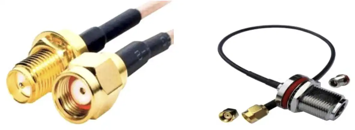
Connector Types | SMA, N-Type, BNC, TNC, 7/16 DIN, 4.3-10 |
Dielectric Material and Design Considerations
The dielectric material in a Coaxial Cable Assembly affects how well the signal works and how hot it can get.
PTFE dielectrics can handle temperatures from -55°C to +200°C and are often chosen for use in defence and aircraft parts. Foam dielectrics lower the dielectric constant, which lowers the attenuation per unit length. This is useful for long telecom cable runs where loss budget is limited.
Silver-plated inner conductors and expanded foam dielectrics lower dB/ft attenuation at high frequencies for high-frequency, low-loss assemblies. The LSZH outer jacket is required in enclosed or occupied areas, like avionics bays, where smoke toxicity is a safety concern according to building and aeroplane standards.
In phased array radar and SATCOM systems, phase stability is an important part of the design process. In these situations, small phase shifts due to cable bending can change the timing of the system and make the beam less accurate. ADM chooses phase-stable materials for parts that will be used in these conditions.
Application Scenarios
5G Telecommunication Infrastructure
When used to connect Remote Radio Units (RRU) to base station antennas in outdoor installations, the assemblies must meet two requirements at the same time: they must have low PIM performance to avoid interference across neighbouring LTE and 5G bands, and they must be durable enough to withstand UV light, rain, and a wide range of temperatures. For these kinds of systems, IP67 or IP68 connector sealing is usually needed.
Aerospace and Defense
To meet the standards of MIL-DTL-17, avionics, radar, and SATCOM assemblies are built. Some important features are high resistance to vibration, the use of LSZH jacket material for safety in occupied aeroplane compartments, and construction that is light. ADM can test these systems over the frequency ranges they use, up to 110 GHz.
Medical Imaging Systems
To keep picture artefacts from happening, the micro-coaxial assemblies inside MRI and ultrasound machines need materials that aren't magnetic. Also, these parts need to have high flex-life rates so they can handle being bent over and over again by moving scanner parts. Choosing the right material and the right termination geometry are both important for getting the flex durability you need.
More Useful Information
Broadcast infrastructure, satellite communication ground systems, wireless network equipment, and microwave measurement setups all depend on cable assemblies that are precisely terminated to keep signal paths stable and low-loss.
Quality Control Process
Before sending an assembly out, ADM tests it against certain parameters. During the whole production process, the following tests are done.
A Vector Network Analyser (VNA) is used for VSWR and Return Loss Testing to make sure that the reflected power at the connector interface meets the required VSWR of less than 1.2:1 across the frequency range.
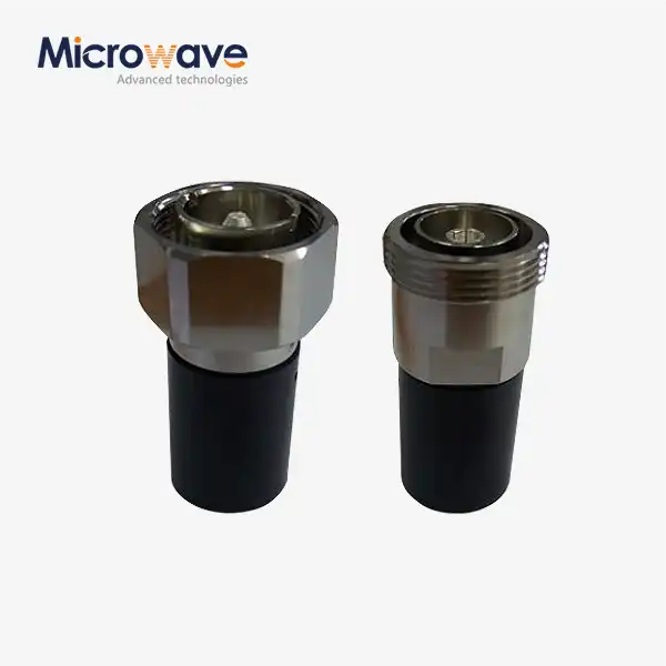
Assemblies with 7/16 DIN or 4.3-10 plugs are put through PIM testing to make sure they work at -160 dBc or better. This proves that the passive intermodulation products from the assembly won't lower the capacity of the cell network in the system that is already in place.
Pull Force and Retention Testing makes sure that the cable body and connector are mechanically connected and that the connection can handle installation stress. The rules for this test are in line with IEC 61169.
Continuity and Hi-Pot Testing looks for short circuits and makes sure that the dielectric layer can handle the needed voltage without breaking.
Salt Spray Testing follows the steps in ASTM B117 for outdoor assemblies, making sure that the connector plating doesn't rust when exposed to salt fog.
Customization and Supply
ADM lets you make your own Coaxial Cable Assembly configurations based on the needs of your project. Some parameters that can be changed are the type of connector, the diameter and length of the cable, the material of the jacket, and the impedance value.
When matching a connector to a wire, the physical dimensions of the cable must be taken into account. Because the dielectric and jacket outer diameters are different, an RG-58 connector can't be used with an LMR-400 cable. When you force a dimensional mismatch, it leads to impedance discontinuities at the termination, higher insertion loss, and a higher chance of mechanical failure at the solder or crimp joint.
To plan the length of a cable, you need to figure out your lost budget. At the working frequency, longer assemblies have more insertion loss. The engineering team at ADM can help you figure out the overall dB loss along a cable run to make sure that the signal level stays above the minimum threshold at the receiver.
ADM has offices in Xi'an, Chengdu, Beijing, Tianjin, and Shijiazhuang, as well as a research and development (R&D) lab. Standard orders and custom engineering projects can be handled at these locations.
FAQ
Q: What's the difference between 75© and 50© coaxial cable assemblies?
A: 50Ω is the standard impedance for RF data and power transmission, including WiFi, cellular, and radar systems, because it balances power handling and attenuation. 75Ω works best for video and CATV applications where keeping the signal's amplitude stable over long distribution runs is the main need.
Q: Why is it important for cellular cable systems to have low PIM performance?
A: Passive intermodulation causes interference in LTE and 5G networks that sit within active receive bands, which limits the network's capacity. Controlled termination methods and non-ferromagnetic materials are used in low PIM systems to keep these intermodulation products below the -160 dBc level.
Q: Can I use connectors from one kind of cable on a different kind of cable?
A: No, connectors are made to fit the dielectric diameter and jacket outer diameter of a certain wire. When you use parts that aren't compatible, you get impedance steps at the junction, more insertion loss, and a mechanical weak point at the termination.
Q: How does the length of the cable affect how well the signal works?
A: There is measured insertion loss for every extra metre of cable, and this loss goes up with frequency. Before you say how long the cable is, you should figure out how much it will lose overall and make sure the signal level at the receiver end stays above the system's lowest usable level.
Q: How small does the bend radius have to be for it to matter?
A: The minimum bend radius is the tightest curve that a wire can make without kinking, dielectric distortion, or impedance spikes in one area. Many people use 5× as a reference for installations with a fixed route and 10× for installations that will be bent over and over again. Always make sure that the number is correct for the type of wire being used.
Q: What range of temperatures do your wire assemblies work with?
A: The temperature range for PTFE-dielectric assemblies is -55°C to +200°C. Different types of insulating materials have different heat limits. The dielectric should be chosen based on the highest and lowest temperatures that the assembly will be exposed to while it is in use.
_1733809032116.webp)