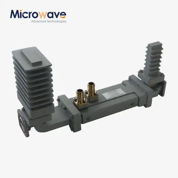
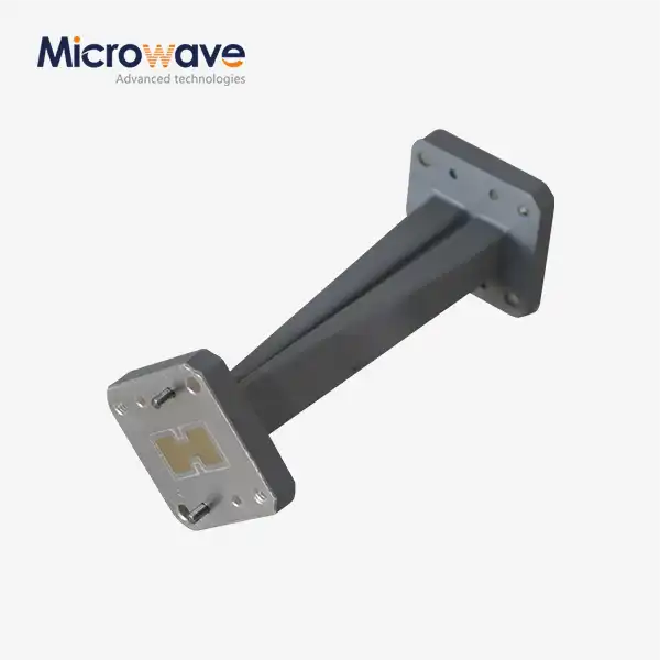
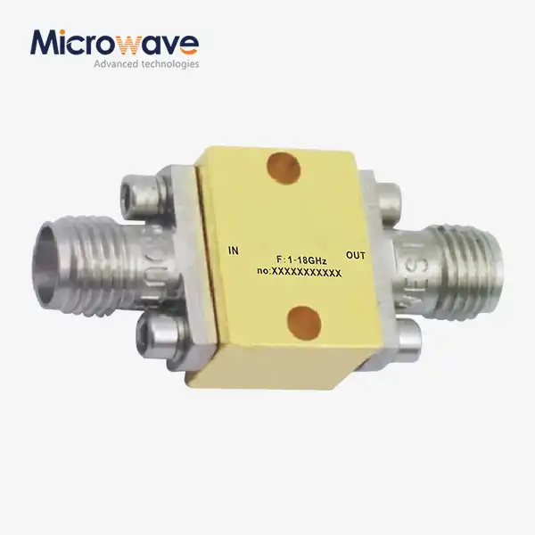
Understanding Waveguide Attenuators: Fixed and Variable Types Explained
Waveguide attenuators are very important parts of current RF and microwave systems because they precisely control the power levels of signals. Procurement experts, technical buyers, and system integrators can make smart choices about where to buy things when they know the basic differences between fixed and variable waveguide attenuators. A waveguide variable attenuator can lower signals by any amount, from 0 dB to 60 dB or higher. This allows for dynamic power management in mission-critical settings like radar calibration, satellite ground station testing, and high-frequency measurement setups where signal integrity must be maintained at all times.
What Are Waveguide Attenuators? A Comprehensive Overview
Waveguide attenuators are precise tools used to lower the intensity of electromagnetic signals in waveguide transmission lines while keeping the quality of the pattern and its phase characteristics. These parts solve some of the most important problems in RF engineering, like keeping sensitive measuring equipment's receivers from getting too full, keeping downstream parts safe from too much power, and creating controlled test settings for system validation.
Core Functions and Design Principles
The main goal is to add measurable insertion loss to the signal stream. Instead of coaxial designs with high-temperature resistance parts, waveguide designs exploit hollow metal structures' air-dielectric properties. This design style handles power better and has reduced parasitic losses, especially at 18 GHz, where cable systems perform poorly.
Building materials impact electrical performance and durability. Commercial employs predominantly aluminium alloys due to their weight-to-strength ratios and ease of machining. Brass alloys can resist higher temperatures for lab equipment. Internal surface treatments like gold plating or chromate conversion coatings reduce oxidation-related insertion loss shift over decades.
Comparing Fixed and Variable Configurations
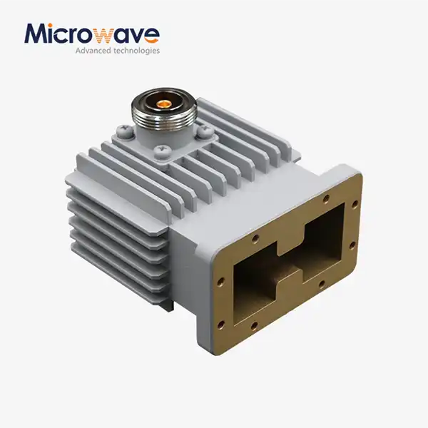
Fixed and mutable types have different applications. Fixed attenuators have rigid resistance sheets or absorptive materials. They give fixed attenuation. Manufacturing processes allow for tight restrictions and precise models with ±0.1 dB accuracy in certain frequency bands. These parts are ideal for lowering power to prevent spectrum scanners from overheating or establishing production test signal levels.
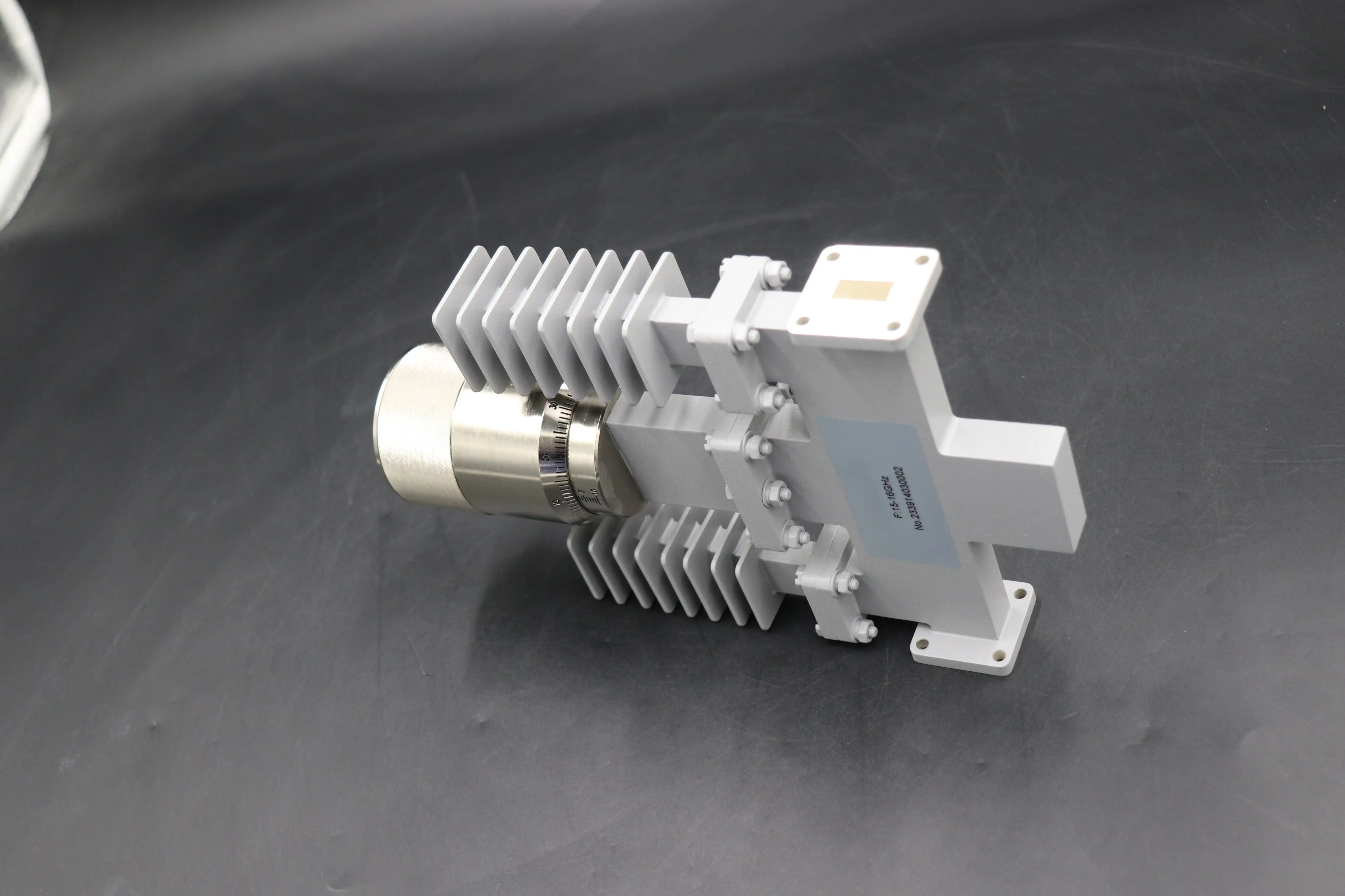
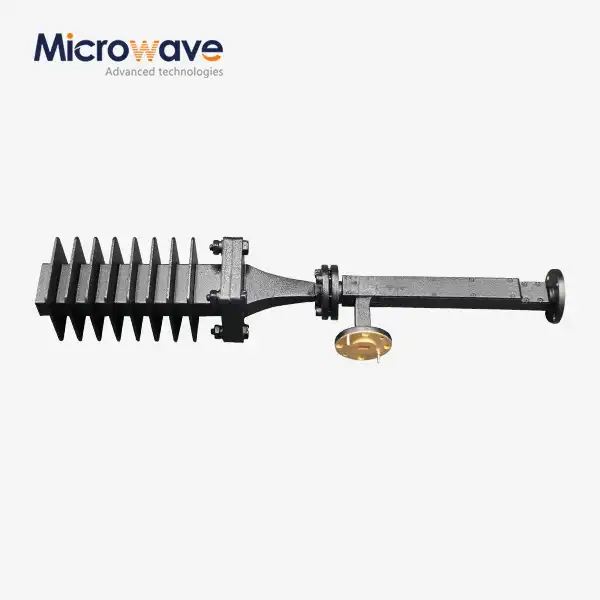
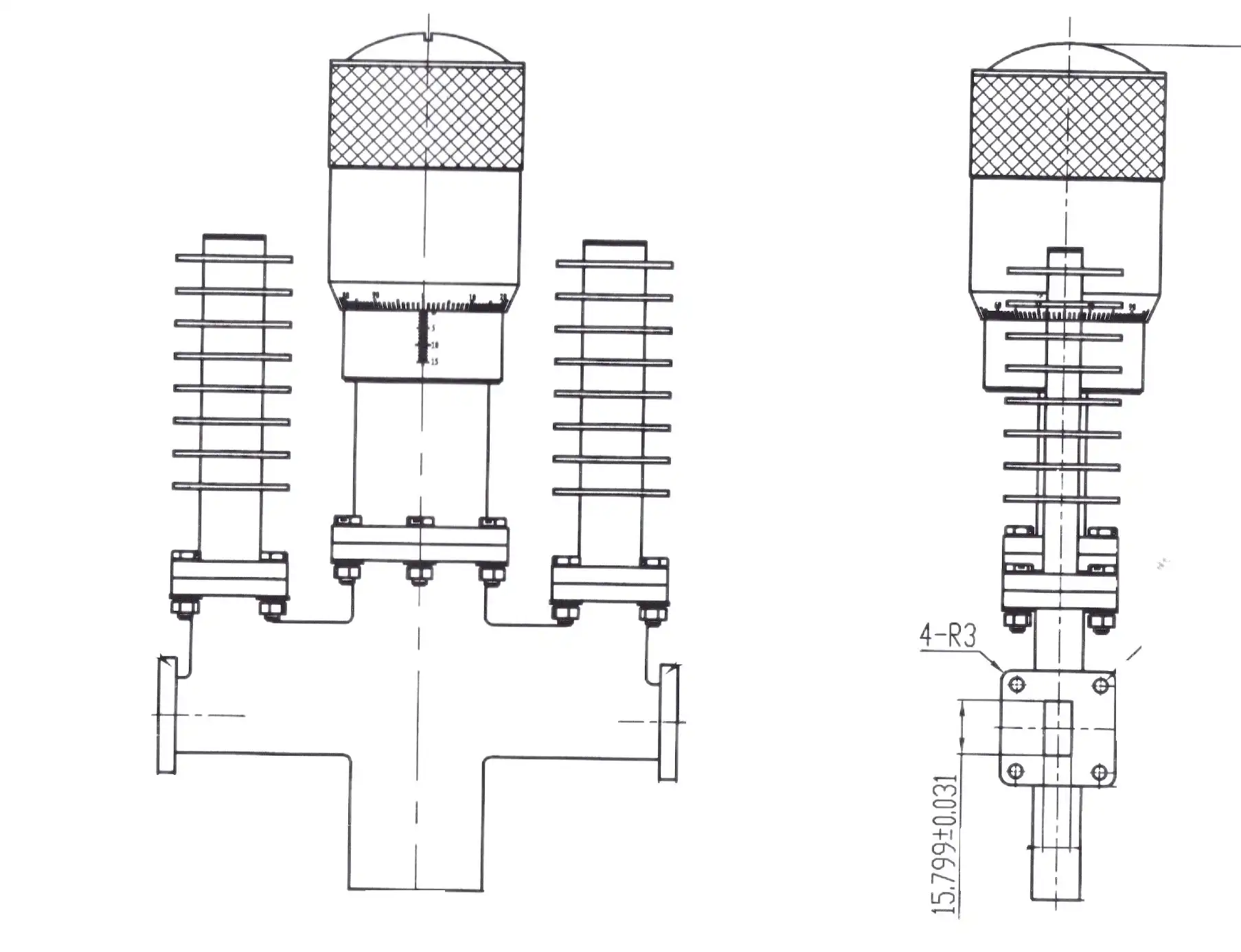
Variable setups have mechanical adjustments that vary electromagnetic field interactions with resistive or absorptive devices. Rotating vane designs that employ polarisation rotation and flap-type attenuators that use resistive vanes to restrict the electric field in the waveguide dominate the market. These are suitable for calibrating vector network analysers and accurate RF measurement due to their phase stability and lower VSWR variation across adjustment ranges.
The following comparison clarifies the technical trade-offs that inform procurement specifications:
| Parameter | Fixed Attenuators | Variable Attenuators |
|---|---|---|
| Attenuation Adjustment | Predetermined value | Continuous or stepped (0-60 dB typical) |
| VSWR Performance | <1.10:1 (constant) | <1.15:1 (across range) |
| Phase Stability | Excellent (no drift) | Good (rotary vane) to Moderate (flap type) |
| Power Handling | High (kilowatt range) | Moderate to High (design-dependent) |
| Typical Cost | Lower | Higher (mechanical complexity) |
| Application Fit | Production environments | Test labs, R&D, calibration |
Knowing these differences helps technical buyers make sure that the specs of the parts they buy meet working needs and price limits.
How Do Waveguide Variable Attenuators Work?
Dynamic power control is possible with waveguide variable attenuators thanks to clever mechanical and electromagnetic interactions. The working principle takes advantage of the basic connection between the strength of an electromagnetic field and the amount of energy absorbed by waveguide structures.
Mechanical Operating Mechanisms
Resistance dielectric blades are coupled to precision linear actuators in flap-type designs. The micrometre-driven mechanism drives the vane further into the waveguide's electric field maximum, binding more energy into the resistive material and turning it into heat. Calibrated dial signs match the mechanical position through attenuation. They typically have 0.01 dB per division resolution. These designs are compact and cheap, but when attenuation increases, they create measurable phase shifts. This should be considered for phase-coherent purposes.
Rotary vane attenuators distinctly employ electromagnetic polarisation theory. In a direct line with the oncoming wave's electric field, a resistant card does not influence the signal. The field direction progressively shifts as this element is turned 90 degrees, causing energy absorption proportionate to the rotation angle. This shape features near-frequency-independent attenuation and a phase shift that is almost constant regardless of attenuation. Vector measurement and automation test tools benefit from this.
Digital controls use microcontrollers with stepper motors or servos. They may be programmed remotely by GPIB, USB, or Ethernet. These improved designs enable working with mechanised manufacturing lines and research test benches more easily, where measurement precision and speed are crucial.
Frequency Compatibility Considerations
The frequency bands available depend on the waveguide size. Each standard waveguide size has a transmission cutoff frequency and an upper frequency limit where higher-order modes reduce measurement accuracy. Direct broadcast satellite systems employ the Ku-band waveguide (WR-62, 12.4-18 GHz) while radar and satellite transmission use the X-band waveguide (WR-90, 8.2-12.4 GHz). New 6G experiments and automobile radar employ millimetre-wave types such as W-band (WR-10, 75–110 GHz).
Inside layer properties affect VSWR and power handling requirements. High-purity absorptive materials and controlled surface roughness preserve standing wave ratios below 1.15:1 across operating bandwidths. This ensures precise measurements in difficult settings. Passive metal heatsinks and active cooling solutions can increase continuous wave power rates to the kilowatt range for testing high-power amplifiers.
Strategic Advantages for Procurement
In some applications, different waveguide variable attenuators are quite useful. Automated test settings reduce labour costs and measurement run times by eliminating part changes. Research laboratories can swiftly swap test points without reconfiguring the system while doing multi-parameter characterisations. Satellite ground station configuration uses dynamic range control to evaluate receiver AGC algorithms in virtual link margin-like scenarios. Over several years, these talents have reduced project schedules and total cost of ownership.
Choosing the Right Waveguide Attenuator for Your Needs
To choose the right waveguide attenuation options, you need to carefully look at how different technical factors and practical needs affect each other. The success of a project depends on the procurement decisions that are made while matching performance requirements with price limits and delivery dates.
Critical Technical Criteria
Attenuation ranges depend on signal level dispersion for each application. For lab systems to quantify component gain compression, the dynamic range must be 40–60 dB to move devices from linear to saturated. Production test equipment for receiver sensitivity standards may only need to adjust 10 to 20 dB around typical signal levels. Setting minimum and maximum reduction levels early in the purchase process keeps costs down while allowing for flexibility.
Frequency interoperability extends beyond waveguide band designations. Specifications should be precise and assess performance throughout the whole range, taking into consideration band-edge VSWR or insertion loss accuracy deterioration. Attenuators with small frequency variation are useful for measuring spread frequencies. However, single-frequency test points can meet tighter standards at unworkable frequencies.
Insertion loss affects error budgets when attenuation is zero. Quality rotary vane attenuators have residual loss of less than 0.3 dB, but inexpensive flap variants may have 0.8 or more. In cascaded measuring systems, cumulative losses worsen signal-to-noise ratios and dynamic range gaps, making this value crucial.
Power management must handle peak power and wave conditions. Satellite transmission testing using kilowatt-output high-power amplifiers requires attenuators that can withstand long-term heat loss. Peak-to-average power levels and duty cycle impacts on heat management are especially critical with pulse radar.
VSWR standards increase mismatch error, affecting measurement accuracy. Modern waveguide attenuators have reflection coefficients of less than -25 dB and setting ranges of 1.12:1 or higher. This performance level ensures little interaction effects between well-matched source and load components.
Comparative Performance Analysis
It is evident whether a waveguide variable attenuator is ideal for a certain application when compared to other technologies. Coaxial step attenuators are inexpensive to start and easy to connect, but they have frequency-dependent insertion loss, low power handling, and significant passive intermodulation. Waveguide designs are more popular in Ka-band and millimetre-wave applications, where coaxial losses make them unsuitable. Coaxial approaches may still be employed in Ku-band applications with small power.
When attenuation values remain constant, fixed waveguide attenuators perform best in terms of stability and VSWR. In production settings with similar device configurations, adopting enhanced fixed-value components instead of over-specified variable units speeds output and lowers capital expenditures. However, study programs that examine diverse devices gain operating flexibility that offsets higher variable attenuator purchase costs by eliminating part storage and reducing setup time.
Manufacturer Landscape and Supplier Selection
Global brands like Keysight Technologies, Pasternack, and Anritsu make a wide range of products with technical information and calibration sources. These companies usually have localised distribution networks for timely shipment and local expertise. These perks are helpful when project deadlines are tight or repairs are unexpected.
Advanced Microwave Technologies Co., Ltd. offers distinct value by customising products and helping with application engineering. We can swiftly create prototypes with non-standard frequency ranges, unusual flange configurations, and optimal mounting setups because we've been creating precise waveguide parts for 20 years. RoHS compliance and ISO 9001:2015 quality management approval ensure defence, military, and business telephony products meet international requirements.
Job planning is heavily influenced by lead time. Major merchants' catalogue products ship within days, while bespoke configurations might take 6–12 weeks, depending on design complexity and manufacturing backlog. Strategic procurement weighs the expenses of safety stock against the advantages of reducing long-lead bespoke part deadlines.
Procurement and Practical Considerations
To buy waveguide variable attenuators globally, you have to deal with technical requirements, seller evaluation factors, and practical problems that all affect the success of the project as a whole. Strategic methods for buying balance the need for success with the needs of the business.
Sourcing Strategies and Supplier Evaluation
Reliable wholesalers like Richardson RFPD and Mouser Electronics stock key manufacturer standard catalogue components. This allows them to easily fulfil requests for typical frequency bands and attenuation ranges. Centralised buying from numerous vendors, payment periods, and common return policies simplifies purchase administration with these channels.
When requirements exceed what is in a catalogue, work with the maker. When you require unique waveguide widths for non-standard frequency ranges, specialised flange setups for existing infrastructure, or greater power levels for specific test circumstances, direct sourcing is ideal. More useful than selling parts, manufacturers who offer application engineering services, including electromagnetic simulation validation, heat analysis, and system integration. This is especially true for complex first-article developments.
Supplier quality management systems should be examined for high dependability or legal compliance documentation. An ISO 9001-approved organisation follows quality processes including design control, process proof, and corrective action. AS9100 clearance is commonly required for aerospace and defence applications to demonstrate additional controls for configuration management, counterfeit part prevention, and supply chain tracking. RoHS and REACH documentation ensures items fulfil European and global environmental standards.
Pricing Dynamics and Budget Planning
Pricing models consider cost considerations such as frequency band complexity, reduction range, and customisation. Standard X-band and Ku-band fixed attenuators are affordable for small quantities, while millimetre-wave variable units are more expensive due to their exact specs and exotic materials. Rotary vane designs should receive 30–50% more funding than flap designs because of their higher phase stability and VSWR performance.
Quantity break restrictions vary by vendor and product family. Catalogue products get 10–15% bulk savings when purchased in 50–100 units annually. Custom design discount rates rise as non-recurring engineering expenditures are amortised. Above 500 units per year, savings are 30–40%. Strategic multi-year arrangements ensure consistent prices and encourage suppliers to maintain their best production slots.
Logistical Considerations and Risk Mitigation
International shipment complicates export control, customs paperwork, and damage risk management. Some countries require authorisation to send ECCN 3A001 or equivalent export control group waveguide parts, which takes 60 to 90 days. Packaging design greatly impacts shipment damage. Foam-lined firm cases, flange safety covers, and shock indicators to document handling are best practices.
Warranties cover production faults for 12–36 months, depending on the item and manufacturer. They seldom cover seals or mechanical bearings. Extended warranty packages and annual testing service contracts allow budgeters to plan and track measures over time. Economic studies should assess the cost of downtime against the price of replacing a part, especially for critical path systems.
Many vendors provide different levels of professional support after the transaction. Applications engineering teams that resolve integration issues or clarify ambiguous requirements speed up program planning and minimise costly design revisions. Renting equipment throughout maintenance cycles keeps the program alive, which is vital when searching for long-term provider agreements.
Conclusion
Waveguide attenuators, which come in both set and changeable forms, are essential parts of current RF and microwave systems used in study, military, space travel, and satellite communications. Variable waveguide attenuators are designed to work in situations where dynamic power control is needed. They can be adjusted over 60 dB while keeping low VSWR and phase stability that aren't possible with coaxial options. When making strategic purchasing choices, technical factors like frequency compatibility, insertion loss, power handling, and VSWR are weighed against commercial factors like source quality systems, customisation options, and lifecycle support infrastructure. Forming relationships with seasoned makers guarantees access to applications engineering know-how, the freedom to make changes, and dependable supply lines that support mission-critical programs.
FAQ
Q1: What frequency ranges do waveguide variable attenuators typically cover?
Waveguide variable attenuators work with frequencies ranging from L-band (1-2 GHz) to W-band (75–110 GHz). Each waveguide size is best for a different band section. X-band (8.2-12.4 GHz) is often used for radar, Ku-band (12.4-18 GHz) is often used for satellite communications, and Ka-band (26.5-40 GHz) is often used for new 5G millimetre-wave systems. Broadband designs with frequency ratios of 1.5:1 offer practical freedom, while narrowband designs with smaller bandwidths meet stricter VSWR requirements.
Q2: How do I choose between fixed and variable waveguide attenuators?
The selection factors are based on what needs to be done. Fixed attenuators work well in production settings that test similar setups because they offer better VSWR steadiness and lower costs. Variable designs are used in lab situations where attenuation needs to be changed often while the device is being characterised or the system is being calibrated. Digitally controlled variable units work best for automatic test routines, while economy flap-type designs work fine for human test processes. Power handling needs and phase stability needs make the design choice even more precise.
Q3: Are waveguide variable attenuators compatible with automated test systems?
Standard connections, such as GPIB, USB, Ethernet, and RS-232 protocols, make it easy for modern waveguide variable attenuators to work with automatic test equipment. Embedded SCPI command sets let you control reduction, do queries, and check the diagnostic state from afar. Stepper motor action allows switching speeds of less than a second, which supports high-throughput production test uses. Putting calibration data in non-volatile memory makes it easier for measurements to be made automatically and for correction factors to be used across swept-frequency measures.
Partner with ADM for Superior Waveguide Variable Attenuator Solutions
Advanced Microwave Technologies Co., Ltd. makes high-quality waveguide variable attenuator components and has been making them for over 20 years. They are also ISO 9001:2015 certified for quality control. Our waveguide variable attenuator portfolio includes designs for X-band to W-band. These are used in defence, military, satellite communication, and research uses that need to be very reliable. We test every part's electrical performance before shipping by using our 24-meter microwave lab testing centre, which can measure up to 110 GHz. This makes sure that all requirements are met and the part is ready to use.
Our applications engineering team works with procurement managers and design engineers to create custom solutions that meet the needs of non-standard frequency ranges, unique flange setups, and higher power handling requirements. Our global transportation network and flexible manufacturing infrastructure allow us to deliver parts that fit your plan and budget, whether you need a few prototypes for quality testing or a lot of parts for a multi-year program. Contact craig@admicrowave.com right away to talk about your waveguide variable attenuator needs and find out how our technical knowledge and focus on customer satisfaction can help you make the best purchases. As a reliable waveguide variable attenuator maker that serves customers all over the world, we are ready to help your mission-critical projects with parts that are made to be accurate and last a long time.
References
1. Pozar, David M. Microwave Engineering, 4th Edition. Hoboken: John Wiley & Sons, 2011.
2. IEEE Standard 149-2021. IEEE Recommended Practice for Antenna Measurements. Institute of Electrical and Electronics Engineers, 2021.
3. Skolnik, Merrill I. Radar Handbook, 3rd Edition. New York: McGraw-Hill Education, 2008.
4. Collier, Russell J. Transmission Lines and RF Networks. Cambridge: Cambridge University Press, 2013.
5. Maas, Stephen A. The RF and Microwave Circuit Design Cookbook. Norwood: Artech House, 1998.
6. Bahl, Inder J. Lumped Elements for RF and Microwave Circuits. Boston: Artech House, 2003.