





High Power Waveguide Isolator vs Circulator Explained
It is very important to know the difference between high power waveguide isolators and circulators when choosing passive microwave devices for RF systems. A high power waveguide isolator is a two-port non-reciprocal device that sends signals in one way and absorbs reflected energy, protecting emitters from backscatter that could be harmful. On the other hand, circulators are three-port parts that move signals from one port to the next in a certain order, which lets you split or combine signals. While both devices use ferrite materials that are pushed by permanent magnets, their different designs make them useful in different areas, such as radar, satellite communications, and internet infrastructure.
Understanding High Power Waveguide Isolators and Circulators
In harsh RF transmission settings, high power waveguide isolators and circulators do more than just route signals. They also protect expensive emitter gear and keep the system's integrity.
What Defines a Waveguide Isolator?
A high power waveguide isolator only lets RF energy flow in one way and stops reverse signals at a matching load. Standing waves caused by impedance mismatches can't get to magnetrons, klystrons, or solid-state amplifiers because of this absorption. Advanced Microwave Technologies Co., Ltd. makes high power waveguide isolators for frequency bands ranging from 0.5 GHz to 110 GHz. These are used in L-band satellite ground stations and millimeter-wave radar systems, among other things. Our isolators have average insertion losses of 0.3 dB and isolation rates above 20 dB, which means that they keep forward signals as stable as possible while reducing reverse energy as much as possible.
Under magnetic bias, the ferrite core inside the isolator turns the electromagnetic field polarity. When forward signals go through, the spin lines up with the waveguide mode, which lets the signal travel. When signals are reflected, they rotate in an opposite direction, sending energy into a resistant load where it cools down. In feeding systems and test-and-measurement setups where resistance changes often, this process is very important.
How Circulators Differ in Operation
Circulators use the same ideas as isolators, but on three or more ports, making directional paths for signals to flow. Energy that goes into Port 1 leaves through Port 2, signs that go into Port 2 come out of Port 3, and so on. This sequence route lets broadcasters and receivers share antennas. It also lets communication systems use duplexers and phased array radars spread signals. Unlike isolators, circulators don't naturally get rid of reverse power; instead, they transfer it, which means that external terminations are needed when port isolation is needed.
A Y-shaped waveguide intersects with a ferrite disk in the middle of the ferrite junction circulator design, which is popular in high-power settings. Magnetic biasing causes phase changes that don't go in the opposite direction, moving messages either clockwise or counterclockwise based on how the ports are set up. Power levels up to several kilowatts can be handled by this design, but as reverse power rises, heat control becomes very important.
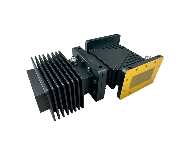
Typical Operating Specifications
Advanced Microwave's high power waveguide isolators work effectively in temperatures ranging from -40°C to +70°C, so they can be used outside in places like satellite earth stations and radar pods in the air. These devices, which are made of metal or copper, are strong mechanically and conduct heat well. Most standards for bandwidth cover 800 MHz, which is enough for broad communication methods and radar patterns that can change frequencies. Forward power handling can handle up to 1000 watts in normal setups. Custom designs can support ongoing operation at multiple kilowatts through better cooling systems.
Technical Comparison: High Power Waveguide Isolator vs Circulator
Buying choices depend on having a complete understanding of the performance requirements and operating limits that are specific to each type of gadget.
Insertion Loss and Isolation Characteristics
Isolators add about 0.3 dB of insertion loss in the forward direction. This is because of ferrite material losses and waveguide gaps. Circulators have about the same amount of loss at each shift (from Port 1 to Port 2). However, based on the design, the total loss across all ports may be between 0.5 and 0.8 dB. Reverse energy reduction is measured by isolation parameters. Isolators achieve a minimum of 20 dB isolation between the input and mirrored ports, which means that less than 1% of the reverse power goes back to the source. Energy entering Port 1 is attenuated by 20+ dB as it moves toward Port 3. Circulators separate ports, but they need careful load matching at ports that aren't being used to stop recycling.
These measurements have a direct effect on emitter safety reserves and system link costs. For weather radar systems that use X-band frequencies, isolation must be higher than 23 dB to stop klystron oscillation when heavy rain backscatters. Isolators that are properly defined can easily meet this requirement.
Power Handling and Thermal Management
The waveguide structure's ferrite temperature properties and dielectric breakdown limits make it hard to handle a lot of power. Standard isolators can handle regular powers of about 1 kW and peak powers of about 10 kW without any active cooling. Differential phase shift isolators use spread-out ferrite elements to handle up to 10 kW of continuous power. They do this by keeping the ferrite elements cool, below the Curie point, with water cooling the housings. Circulators have the same temperature limits, but during regular operation, they don't get as hot because they don't have any dissipative loads.
When peak powers are high, arcing is a clear way for something to fail. Around 3 MV/m field strength, the dielectric breakdown happens in air-filled waveguides, which limits the peak power in small shapes. Adding nitrogen or SF6 gas to the air raises the breaking point, which is a method used in aircraft uses at high altitudes where the air pressure drops a lot.
Frequency Bandwidth and Physical Dimensions
Bandwidth speed goes down as a gadget gets smaller. Broadband isolators with octave bandwidths need tapering ferrite sections and stepped transformers, which makes the length of the device longer. When designed for a 10-15% tiny bandwidth, narrowband designs get the smallest size possible, which is helpful for satellite payloads that don't have a lot of room. Since the joint design in circulators has stronger resonance properties, they usually have smaller initial bandwidths than isolators. At Advanced Microwave, our engineering team changes the bandwidth and form factor to fit different mission profiles, from military onboard systems to UAV data links, by using custom ferrite formulas and magnetic circuit optimization.
Procurement Guide: Selecting the Right Device for Your Needs
When you strategically source waveguide passive components, you need to make sure that your technical needs, the supplier's skills, and the cost over the life of the product all line up.
Matching Power Ratings to Application Demands
System builders have to look at the highest and lowest amounts of power at the device, taking into account losses in the transmission lines and component derating. For thermal safety, satellite uplink amplifiers that produce 500 watts of CW output need isolators that can handle 1000 watts of forward power. This is especially important when the temperature outside is very high or very low. Pulsed radar emitters with a peak output of 50 kW and low duty cycles can use normal isolators as long as the average power stays below the heat limits. Specifications that don't match up cause early failures like ferrite demagnetization, load burnout, or waveguide arcing, which costs a lot to replace in the field and causes downtime.
Evaluating Supplier Credentials and Customization Capacity
Professionals in charge of buying things should give preference to companies that are certified with ISO 9001:2015 and have strong quality control systems in place during the planning, production, and testing stages. RoHS compliance makes sure that European and North American markets follow material limits. Advanced Microwave keeps its ISO 14001:2015 environmental approval and ISO 45001:2018 safety standards for workers, which shows that it is doing a great job overall.
The ability to customize sets basic sellers apart from technical partners. We offer OEM services that include retuning the frequency, making changes to the flange, and weather protection, which includes pressurization for altitude, urethane covering for resistance to dampness, and vibration testing according to MIL-STD-810. Rapid prototyping services let you test your idea before committing to it for production, which lowers the technical risk of new system layouts.
Supply Chain Considerations and Delivery Performance
Standard waveguide isolators have lead times of two to four weeks, based on the frequency band and the number of flanges. Custom designs add six to eight weeks to the time frame, and our 24-meter microwave lab is used for repeated electromagnetic modeling and prototype testing. This building lets you test antennas and parts from 0.5 to 110 GHz, making sure they work well in controlled far-field situations. Defense contractors and telecom infrastructure builders who have to plan deployments that last more than one year can save money by signing bulk buying deals and taking advantage of volume savings and sale inventory programs.
Global export operations through established freight companies make sure that all paperwork is in order and that travel times are known ahead of time. Our position in Shenzhen is close to major container ports, which makes shipping ocean freight to delivery hubs in North America and Europe cheaper.
Installation and Maintenance Best Practices
Integrating devices correctly and following preventative maintenance plans can make them last longer and keep system performance gaps.
Installation Procedures for Optimal Performance
To keep electromagnetic leaks and mechanical stress from happening, high power waveguide isolators need to have their flanges perfectly lined up. The surroundings must be compatible with the gasket material, which is usually indium or silicone. Indium gaskets are better at conducting electricity in precise uses, while silicone gaskets can handle temperature cycles in outdoor setups. Manufacturers specify a torque range of 10-15 foot-pounds for flange bolts, which makes sure that pressure is spread evenly and doesn't cause flanges to bend.
Orientation is important. Because these resistant parts break down over time from absorbing power, load terminations on isolators should be mounted so that they can be easily inspected and replaced. Attention must be paid to the order of the ports on circulators because wrong links can mess up signal flow and cause the system to stop working. Strain relief is needed for cable assemblies and waveguide runs that join to isolators so that mechanical stress doesn't change the resistance qualities.

Routine Maintenance and Troubleshooting
Inspections that happen every 12 to 18 months find problems early on. A visual inspection shows that the metal housings are corroding, especially in marine settings, and the flange surfaces are oxidizing, which makes the electrical contact weaker. Vector network testers measure VSWR to find out how much impedance drift there is. Readings higher than 1.15:1 indicate internal degradation or contamination. Isolation testing, which is usually done with directional couplers built into transmission systems, makes sure that reverse loss stays within the limits.
Using thermal imaging during operation shows hot spots that mean the ferrite is losing its magnetic properties or the load is failing. Temperatures above 80°C on the outside of the gadget should be looked into right away. Our technical support team can be reached at craig@admicrowave.com. They offer online tests and fast shipping of replacement parts to keep mission-critical systems running as smoothly as possible.
Emerging Trends and Future Outlook in Waveguide Components
Waveguide component growth paths are changed by changing market needs and new technologies.
Advanced Materials and Miniaturization
Adding yttrium-iron-garnet (YIG) to low-loss ferrite mixtures lowers insertion loss to less than 0.2 dB and raises Curie temperatures above 250°C. These materials make it possible for higher power levels in smaller sizes, which is very important for next-generation phased array radars and small satellite transmission devices. Additive manufacturing creates complicated waveguide shapes that can't be made with traditional cutting. This lets isolators be built directly into antenna feed structures and makes assembly simpler.
Graphene-based absorptive materials are being studied in the lab and show promise for having broadband properties that are better than traditional resistive loads. This could lead to octave-bandwidth isolators with low size costs. These kinds of new ideas are in line with what 5G millimeter-wave infrastructure needs. Small, broad passive components make rollout cheaper.
Market Drivers in Defense and Space Applications
As part of efforts to update the military, electronic warfare systems that need strong defense against enemy jamming are given top priority. high power waveguide isolators with fast heat recovery allow for continuous operation during multi-pulse engagements, which is a feature that is being asked for more and more in radar update contracts. Space-qualified isolators go through strict radiation tolerance and outgassing tests. They support mega-constellation satellite launches where mission success over a ten-year lifespan depends on how reliable the parts are.
Commercial space projects, like data networks in low Earth orbit, increase the need for waveguide parts that are light and cheap. Our changes to the production process cut costs by 30% compared to older designs while keeping performance at an aerospace level. This makes ADM a key partner for NewSpace projects that need to balance performance and budget.
Conclusion
Before choosing between high power waveguide isolators and circulators, you need to carefully think about how the signals need to move, how much power they need to handle, and how safe the system needs to be. Isolators protect receivers in places where resistance changes often by allowing one-way transfer and reverse power absorption. Circulators allow signals to be routed through multiple ports, which supports antenna sharing and duplexer features. Advanced Microwave Technologies Co., Ltd. makes both types of devices, and their dependability has been tested in defense radar, satellite communications, and aircraft navigation systems. Our production is ISO-certified, we can make a lot of changes, and we offer full expert help to make sure that buying choices lead to operating excellence. When it comes to mission-critical applications, working with a skilled provider lowers technical risks and raises operational costs.
FAQ
Q1: What is the fundamental difference between an isolator and a circulator?
An isolator is a two-port device with an internal closure that lets signals go forward while collecting energy that is reflected back. A circulator is a three-port part that sends data from one port to the next in a certain order without absorbing them. Isolators keep emitters safe from echoes, and circulators let you split or combine signals.
Q2: Can isolators handle low-power applications effectively?
While they are often too specific in these situations, the answer is yes. Coaxial isolators can save money for devices with less than 10 watts of power. Waveguide isolators work best in places with a lot of power because they can handle the heat and voltage drops that come with it, even though they are bigger and more expensive.
Q3: How do I select the appropriate frequency range?
Make sure that the bandwidth of the isolator or circuit matches the working range of your device. Frequency-agile radar and multi-band transmission systems can use wideband devices that cover 20 to 30 percent of the bandwidth. When used in fixed-frequency applications, narrowband parts that are designed for 5–10% bandwidth offer better insertion loss and separation.
Q4: What cooling methods extend power handling?
For average powers below 1 kW, passive cooling through housings made of metal or copper is enough. For constant power handling up to 10 kW or more, water-cooled jackets or forced-air convection are needed. This is important in industrial heaters and long-range monitoring radar uses, where duty cycles are close to 100%.
Partner with ADM for Premium Waveguide Solutions
Advanced Microwave Technologies Co., Ltd is ready to help you with your buying needs by designing high power waveguide isolators that are reliable and work well. Our engineering team uses more than 20 years of experience with microwaves, ISO 9001:2015-certified production, and a 24-meter microwave studio to make sure that the parts we give meet the strictest requirements. We offer full support from the first meeting all the way through installation and maintenance, whether you need standard stock goods that can be delivered quickly or custom OEM solutions that are made to fit your specific frequency bands and weather conditions. Email craig@admicrowave.com to talk about the needs of your application and get full scientific information. As a reliable company that makes high power waveguide isolators, we offer low prices, the ability to ship our products all over the world, and quick customer service after the sale that makes your supply chain more resilient. Work with ADM to make sure you have the inactive parts that your important systems need.
References
1. Helszajn, J. (2008). Ferrite Circulators and Isolators: Theory and Practice. London: IET Publishing.
2. Pozar, D. M. (2011). Microwave Engineering, Fourth Edition. Hoboken: John Wiley & Sons.
3. Baden Fuller, A. J. (1987). Ferrites at Microwave Frequencies. London: Peter Peregrinus Ltd.
4. Linkhart, D. K. (2009). Microwave Circulator Design, Second Edition. Boston: Artech House.
5. Collin, R. E. (2001). Foundations for Microwave Engineering, Second Edition. New York: IEEE Press.
6. Montgomery, C. G., Dicke, R. H., & Purcell, E. M. (1948). Principles of Microwave Circuits. New York: McGraw-Hill.
YOU MAY LIKE
 VIEW MORELog Periodic Antenna
 VIEW MOREBroadband Coaxial Circulator
 VIEW MOREWG High Pass Filter
 VIEW MOREDouble-Ridged Waveguide Magic Tee
 VIEW MOREPyramid Horn Lens Antenna
 VIEW MOREUltra Double-ridged Horn Antenna
 VIEW MORELadder Membrane Conical Dual circular Polarization Horn Antenna
 VIEW MOREConical Linear Polarization Horn Antenna
