The Ultimate Guide to RF Attenuators: Definition, Functions, and Applications
In modern RF systems, engineers constantly face a critical challenge: how to precisely control signal strength without compromising system integrity or causing component damage. A coaxial variable attenuator emerges as the solution to this pressing problem, offering adjustable signal attenuation that prevents overload conditions, optimizes impedance matching, and ensures reliable performance across telecommunications, aerospace, and defense applications. This comprehensive guide explores everything you need to know about RF attenuators, from fundamental definitions to real-world implementations, helping you select the right solution for your specific requirements.
What Are RF Attenuators and Why Are They Essential?
RF attenuators are passive electronic components designed to reduce the power or amplitude of radio frequency signals in a controlled and predictable manner. Unlike amplifiers that boost signal strength, attenuators systematically weaken signals while maintaining waveform integrity and frequency characteristics. The attenuation level is typically expressed in decibels, with common values ranging from 3 dB to 30 dB or more depending on application requirements. The fundamental working principle involves converting a portion of the RF signal energy into heat through carefully designed resistive networks. These networks can be configured in various topologies including T-type, π-type, and bridged-T configurations, each offering specific advantages for different impedance matching scenarios. The resistive elements are precisely calculated to provide the desired attenuation while maintaining the characteristic impedance of the RF system, typically 50 ohms for most coaxial applications. RF attenuators serve multiple critical functions in modern communication systems. They protect sensitive receiver components from excessive signal levels that could cause saturation or permanent damage. In test and measurement applications, attenuators enable accurate calibration by reducing signal strength to levels compatible with measurement equipment specifications. They also play a vital role in impedance matching between components with different input and output impedance levels, minimizing signal reflections and standing wave ratio issues that can degrade system performance.
Understanding Coaxial Variable Attenuator Technology
A coaxial variable attenuator represents an advanced category of RF attenuation devices that provides adjustable signal reduction rather than fixed values. This adjustability makes them indispensable in applications requiring dynamic signal control, such as automatic gain control circuits, power leveling systems, and complex test environments where signal conditions vary continuously. The variable attenuation mechanism can be implemented through several technologies including PIN diodes, voltage-controlled resistive elements, or mechanically adjusted resistor networks. The coaxial construction ensures excellent frequency response and low voltage standing wave ratio across the operational bandwidth. Modern coaxial variable attenuators typically operate from DC to 18 GHz or higher, with some specialized units extending to 40 GHz and beyond. The coaxial design inherently provides good shielding against electromagnetic interference, making these devices particularly suitable for environments with high RF field strengths or multiple signal sources operating simultaneously.Advanced coaxial variable attenuators incorporate sophisticated control interfaces ranging from simple manual adjustment knobs to digitally programmable interfaces compatible with automated test equipment and remote control systems. The attenuation range typically spans from 0 to 30 dB with resolution as fine as 0.1 dB in high-precision models, enabling operators to achieve exact signal levels required for specific measurement or operational scenarios. Insert loss, a critical specification, measures the signal degradation introduced when the attenuator is set to minimum attenuation, with quality units maintaining insertion loss below 1 dB across their frequency range.
Types of RF Attenuators and Their Specific Applications
The RF attenuator family encompasses several distinct categories, each engineered for particular operational requirements and deployment scenarios. Understanding these categories helps engineers select optimal solutions that balance performance, cost, and functional requirements.
Fixed RF Attenuators for Stable Signal Control
Fixed RF attenuators provide a predetermined, unchangeable attenuation value, making them ideal for applications requiring consistent signal reduction without the complexity of adjustment mechanisms. These devices feature simple construction with precision resistor networks permanently configured to achieve specific attenuation levels. Common fixed values include 3 dB, 6 dB, 10 dB, and 20 dB, with manufacturers offering extensive libraries covering virtually any required attenuation value. The primary advantages of fixed attenuators include excellent reliability due to their passive nature, minimal insertion loss, outstanding power handling capabilities, and cost-effectiveness compared to variable alternatives. They exhibit exceptional stability over temperature variations and extended operational periods, making them suitable for permanent installations in satellite ground stations, base station infrastructure, and radar systems where signal levels remain constant. Fixed coaxial variable attenuator principles apply to these devices, though the attenuation value cannot be adjusted after manufacturing. In telecommunications infrastructure, fixed attenuators compensate for excessive signal gain in RF distribution systems, preventing receiver overload in cellular base stations and distributed antenna systems. Aerospace applications utilize fixed attenuators to calibrate antenna test ranges and protect sensitive navigation receiver inputs from high-power interference sources. The simplicity of fixed attenuators makes them particularly attractive for high-reliability applications where moving parts or electronic control systems might introduce failure modes.
Variable and Step Attenuators for Dynamic Applications
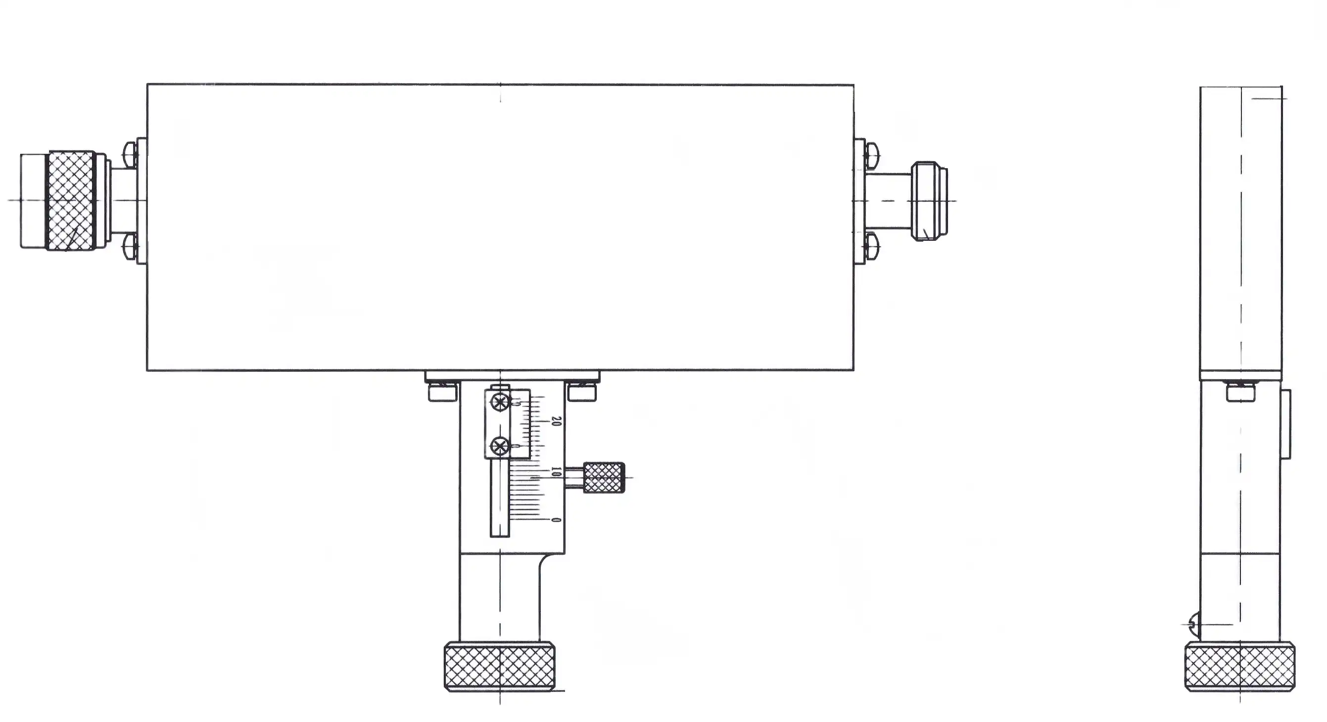
Variable RF attenuators provide continuous adjustment of attenuation levels across their specified range, offering maximum flexibility for applications requiring frequent signal strength modifications. These devices employ various control mechanisms including manual dials, motorized actuators, voltage control inputs, or digital interfaces. The coaxial variable attenuator design enables smooth transitions between attenuation states without introducing signal discontinuities or phase distortions that could disrupt sensitive measurements or communication links. Step attenuators represent a middle ground between fixed and continuously variable types, offering discrete attenuation increments typically in binary sequences such as 1 dB, 2 dB, 4 dB, 8 dB, and 16 dB. By combining these steps using switch networks, users can achieve any attenuation value up to the maximum in 1 dB increments. This approach provides the flexibility of variable attenuation while maintaining the excellent repeatability and accuracy associated with fixed attenuator sections. Electronic switching using PIN diodes or FET transistors enables fast switching speeds measured in microseconds, essential for automatic gain control circuits and adaptive signal processing systems. Laboratory environments extensively utilize variable coaxial variable attenuators for equipment calibration, device characterization, and research applications requiring precise signal level control. Communications systems employ variable attenuators in feedback loops that automatically adjust transmitter power or receiver sensitivity in response to changing propagation conditions. Military and aerospace systems integrate step attenuators into electronic warfare equipment, signal intelligence systems, and advanced radar installations where rapid signal level adjustment supports mission-critical operations.
Key Technical Specifications for Coaxial Variable Attenuators
Selecting the appropriate coaxial variable attenuator requires careful evaluation of multiple technical parameters that determine device performance in specific applications. Understanding these specifications enables engineers to match attenuator capabilities with system requirements, avoiding both over-specification that increases costs and under-specification that compromises performance.
Frequency Range and Bandwidth Considerations
The operational frequency range defines the spectrum over which an attenuator maintains specified performance characteristics. Entry-level coaxial variable attenuators typically cover DC to 18 GHz, adequate for most commercial wireless communication bands including cellular, WiFi, and satellite communication frequencies. Advanced models extend coverage to 40 GHz or 110 GHz, addressing millimeter-wave applications such as 5G mmWave bands, automotive radar systems operating at 77 GHz, and emerging 6G research frequencies. Attenuation flatness across the frequency range represents a critical specification, indicating how consistently the device maintains its nominal attenuation value at different frequencies. Premium coaxial variable attenuators achieve flatness within ±0.5 dB across their entire bandwidth, ensuring accurate signal control regardless of operating frequency. Applications involving wide-bandwidth signals or frequency-hopping systems particularly benefit from excellent flatness specifications, as frequency-dependent attenuation variations could distort signal characteristics or create measurement errors. The voltage standing wave ratio specification quantifies impedance matching quality, with lower values indicating better matching to the system characteristic impedance. VSWR values below 1.3:1 across the operational bandwidth represent excellent performance, minimizing signal reflections that could create standing waves, reduce power transfer efficiency, and introduce measurement uncertainty. High-frequency applications operating above 20 GHz demand particularly stringent VSWR specifications, as even small impedance mismatches create significant reflections at these frequencies.
Power Handling and Insertion Loss Performance
Power handling capability determines the maximum RF power an attenuator can safely process without thermal damage or performance degradation. Coaxial variable attenuators typically handle average power levels from 1 watt to 100 watts or more, with specific values depending on physical size, resistor element construction, and heat dissipation design. Peak power handling becomes critical in pulsed radar applications where instantaneous power levels may greatly exceed average power, requiring attenuators designed specifically for high peak power scenarios. Insertion loss measures the signal degradation introduced when the attenuator operates at minimum attenuation setting, representing unavoidable losses from connector transitions, transmission line discontinuities, and control element resistance. Quality coaxial variable attenuators maintain insertion loss below 1 dB, with premium models achieving values as low as 0.5 dB. Lower insertion loss proves particularly important in receiver front-end applications where every decibel of signal loss directly degrades system noise figure and sensitivity. Temperature stability specifications indicate how attenuator performance varies with environmental temperature changes. Military and aerospace applications operating across temperature ranges from -40°C to +85°C require attenuators with excellent temperature compensation, typically achieving attenuation variation less than 0.01 dB per degree Celsius. Commercial applications with controlled environments can accept more relaxed temperature specifications, trading absolute stability for reduced cost.
Real-World Applications of Coaxial Variable Attenuators
Coaxial variable attenuators find deployment across diverse industries and applications, each leveraging specific attenuator capabilities to solve unique technical challenges. Understanding these applications provides insight into device selection criteria and implementation best practices.
Telecommunications Infrastructure and Network Optimization
Modern telecommunications networks rely extensively on coaxial variable attenuators for signal level management in base stations, distributed antenna systems, and satellite ground terminals. In cellular base stations, attenuators compensate for variations in feeder cable length between the base station equipment and antenna installations, ensuring consistent signal levels reach remote radio heads regardless of installation specifics. This optimization prevents receiver saturation during strong signal conditions while maintaining adequate signal strength during marginal coverage scenarios. Satellite communication ground stations utilize coaxial variable attenuators to adjust uplink power levels, compensating for atmospheric attenuation variations caused by rain fade, weather conditions, and satellite position changes relative to earth station locations. The ability to precisely control transmitted power prevents adjacent satellite interference while maintaining link quality during adverse conditions. Downlink paths employ attenuators to protect sensitive low-noise amplifiers from excessive signal levels during clear-sky conditions or when tracking high-power satellites. Fiber optic networks increasingly incorporate RF systems for remote antenna configurations, requiring coaxial variable attenuators in radio-over-fiber applications. These installations adjust RF signal levels feeding electro-optic converters, optimizing the dynamic range utilization of optical links while preventing distortion from excessive modulation depths. Network optimization teams employ portable variable attenuators during installation and maintenance activities, enabling field technicians to measure system performance under various signal level conditions without requiring elaborate test equipment configurations.
Aerospace, Defense, and Radar System Integration
Military and aerospace applications demand coaxial variable attenuators meeting stringent reliability, environmental, and performance specifications. Airborne radar systems integrate step attenuators in receiver protection circuits, rapidly switching attenuation states to prevent receiver damage from nearby high-power transmitters while maintaining sensitivity for weak target returns. The microsecond switching speeds achievable with PIN diode-based step attenuators enable real-time adaptation to rapidly changing threat environments. Electronic warfare systems utilize banks of coaxial variable attenuators to simulate complex signal environments for training and evaluation purposes. By precisely controlling signal levels from multiple emitters, operators can recreate realistic threat scenarios testing defensive system capabilities without requiring expensive flight test operations. The wide dynamic range and excellent linearity of quality variable attenuators ensure accurate simulation of both strong nearby emitters and distant weak signals operators might encounter in operational environments. Navigation and communication systems aboard aircraft and spacecraft employ coaxial variable attenuators for signal conditioning, automatic gain control, and transmitter power adjustment. The extreme temperature ranges, vibration levels, and radiation exposure characteristic of aerospace environments require specially qualified attenuators meeting rigorous military specifications. These devices must maintain performance throughout the mission profile while withstanding shock loads during launch or landing operations that would destroy commercial-grade components.
Test and Measurement Laboratory Applications
Engineering laboratories conducting RF and microwave device characterization rely on coaxial variable attenuators as fundamental test equipment. Amplifier testing requires precise input signal control to measure gain, linearity, and compression characteristics across specified input power ranges. Variable attenuators provide this control without requiring multiple signal generators or introducing the phase noise and spurious signal issues associated with signal generator internal attenuator networks. Antenna measurement facilities employ coaxial variable attenuators in both transmission and reception paths, compensating for antenna gain variations during pattern measurements or adjusting signal levels to prevent receiver overload when measuring high-gain antennas at close range. The 24-meter microwave darkroom facilities use precision attenuators to calibrate measurement systems, establishing accurate reference levels essential for deriving antenna parameters from raw measurement data. Automated test systems integrate digitally controlled coaxial variable attenuators under computer control, enabling unmanned device characterization running overnight or over extended duration reliability tests. The digital interfaces typically employ USB, Ethernet, or GPIB protocols, seamlessly integrating with test automation software platforms like LabVIEW or Python-based measurement frameworks. This automation capability dramatically increases test throughput while improving measurement repeatability by eliminating manual adjustment errors.
Selecting and Implementing Coaxial Variable Attenuators
Successful coaxial variable attenuator integration requires careful consideration of system requirements, environmental factors, and operational scenarios. Following systematic selection procedures and implementation best practices ensures optimal performance and long-term reliability.
Critical Selection Criteria and Trade-offs
The selection process begins with defining operational frequency range, required attenuation range, and power handling requirements based on system specifications. Applications spanning multiple frequency bands may require multiple attenuators optimized for different frequency ranges rather than attempting to cover all bands with a single wideband device. The coaxial variable attenuator specifications must meet or exceed system requirements with adequate margin accounting for component tolerances and aging effects. Connector compatibility represents another essential consideration, with SMA connectors suitable for frequencies up to 18 GHz, 2.92mm or 2.4mm connectors extending to 40 GHz, and 1.85mm or 1.0mm connectors addressing requirements above 65 GHz. Mixing connector types requires adapters introducing additional insertion loss and potential VSWR degradation, making standardization on single connector types advantageous when possible. Thread type variations including standard SMA and SMA with captivated contact interfaces require attention to ensure mechanical compatibility. Control interface selection balances operational requirements against system complexity and cost. Manual adjustment suffices for laboratory applications with infrequent changes, while automated test systems demand digital control interfaces. Voltage-controlled attenuators offer simplicity for analog control loops but require stable, low-noise control voltage sources. The control interface choice impacts system integration complexity and should align with existing infrastructure capabilities.
Installation Best Practices and Performance Optimization
Proper installation significantly impacts coaxial variable attenuator performance and reliability. Torque specifications for connector mating must be observed, typically 7-10 inch-pounds for SMA connectors and proportionally higher for larger connector types. Over-tightening damages connector interfaces and may deform center conductors, while under-tightening creates unreliable connections susceptible to intermittent contact and arcing. Using calibrated torque wrenches eliminates guesswork and ensures consistent, reliable connections. Environmental considerations include operating temperature range, humidity exposure, and vibration levels. Applications in uncontrolled environments benefit from attenuators with sealed construction protecting internal components from moisture ingress and contamination. Vibration-prone installations such as mobile platforms or equipment subject to transportation require attenuators designed for mechanical shock and vibration, typically meeting MIL-STD-810 environmental testing standards. Power dissipation creates heat requiring adequate thermal management in continuous high-power applications. Heat sinking attenuator bodies to larger metal structures improves thermal performance, while ensuring adequate air circulation around free-standing installations prevents localized hot spots. Thermal infrared imaging during initial system testing identifies potential thermal issues before they cause reliability problems or performance degradation.
Advanced Microwave Technologies Co., Ltd. Product Capabilities
Advanced Microwave Technologies Co., Ltd. provides comprehensive coaxial variable attenuator solutions addressing diverse industry requirements. The product portfolio includes both variable and fixed attenuators with operating frequencies spanning DC to 40 GHz, covering virtually all commercial and military communication bands. The exquisitely designed products deliver good quality and high precision performance comparable to leading international manufacturers. The coaxial variable attenuator offerings feature frequency ranges from DC to 18 GHz with customization available for specific application requirements. Standard attenuation ranges span 0-30 dB with insertion loss below 1 dB, ensuring minimal signal degradation when operating at minimum attenuation settings. Power handling capabilities reach 100 watts average power, accommodating high-power transmitter testing and communications infrastructure applications. Multiple connector options including SMA, N-Type, and BNC interfaces ensure compatibility with existing system infrastructure. Advanced Microwave's coaxial variable attenuators deliver precise signal control with adjustable attenuation and high accuracy, helping fine-tune system performance across telecommunications, aerospace, and defense applications. The wide frequency range supports diverse applications from low-frequency communications to high-frequency radar systems, while low insertion loss minimizes signal degradation ensuring high-quality signal transmission. The compact design facilitates easy integration into existing systems without extensive modifications, and efficient operation reduces energy consumption contributing to overall system efficiency. Technical features include high-performance designs handling high-power signals without affecting system integrity, ensuring consistent performance over extended operational periods. The flexible attenuation control provides users with precise control over signal strength across various power levels, essential for dynamic signal management in complex RF environments. The devices operate reliably across temperatures from -40°C to +85°C, meeting demanding environmental specifications for outdoor installations and mobile platforms. Housing materials include aluminum and stainless steel options, with all products maintaining RoHS compliance and ISO:9001:2008 certification.
Conclusion
RF attenuators, particularly coaxial variable attenuators, serve as indispensable components enabling precise signal control across telecommunications, aerospace, defense, and test measurement applications. Understanding attenuator types, specifications, and implementation best practices empowers engineers to select optimal solutions delivering reliable performance throughout demanding operational environments.
Cooperate with Advanced Microwave Technologies Co., Ltd.
Advanced Microwave Technologies Co., Ltd. stands as your trusted China Coaxial Variable Attenuator manufacturer, China Coaxial Variable Attenuator supplier, and China Coaxial Variable Attenuator factory, offering High Quality Coaxial Variable Attenuator for sale at competitive Coaxial Variable Attenuator prices. With over 20 years of expertise in microwave products, ISO certifications including ISO 9001:2015, ISO 14001:2015, and ISO 45001:2018, plus state-of-the-art testing capabilities up to 110 GHz in our 24m Microwave Darkroom, we deliver customized solutions through comprehensive OEM services including design support, prototyping, and fast turnaround times. Whether you need China Coaxial Variable Attenuator wholesale solutions for large-scale deployments or specialized configurations for unique applications, our expert engineering team provides technical assistance from specification through installation. Contact us today at craig@admicrowave.com to discuss your requirements and experience the Advanced Microwave advantage in precision RF components.
References
1. "Attenuator (electronics)" by Wikipedia Contributors, Wikipedia Foundation
2. "RF Demystified—What Is an RF Attenuator?" by Analog Devices Engineering Team, Analog Devices Technical Publications
3. "What is an RF Attenuator - basics, types, symbols" by Ian Poole, Electronics Notes Technical Reference
4. "RF Attenuators and Their Applications in Aerospace" by ERSA Electronics Engineering Department, ERSA Electronics Technical Documentation
YOU MAY LIKE
 VIEW MORELow Phase Noise Amplifier
 VIEW MOREAc Power Amplifier
 VIEW MOREVoltage Controlled Phase Shifter
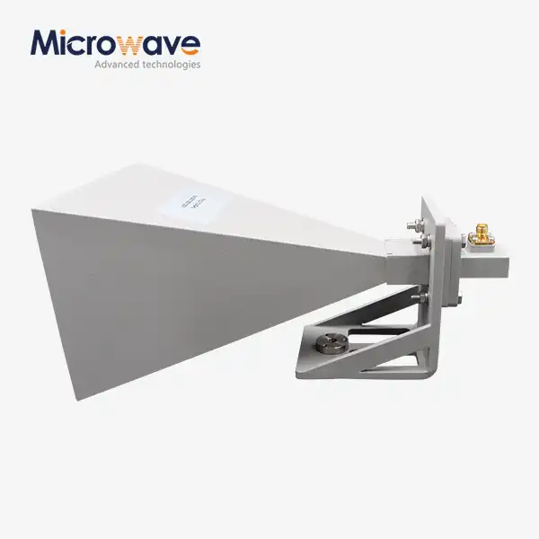 VIEW MOREStandard Horn Antenna
 VIEW MOREConical Horn Lens Antenna
 VIEW MOREPoint Focusing Horn Lens Antenna
 VIEW MORECorrugated Horn and Multimode Horn Antenna
 VIEW MOREMini Wideband Double-ridged Horn Antenna


