How To Make Waveguide Tubes To Better Meet The Requirements Of Radar Level Meter Installations?
Industrial facilities face a critical challenge when radar level meters fail to deliver accurate measurements due to turbulent conditions, foam generation, or liquid level fluctuations inside storage tanks. The Waveguide Tube solution addresses this pain point by focusing microwave pulses and reducing signal scattering, ensuring precise level measurement even in the most demanding environments. Making waveguide tubes that truly meet radar level meter installation requirements demands careful attention to material selection, dimensional specifications, and structural design parameters.
Understanding Waveguide Tube Design Fundamentals for Radar Applications
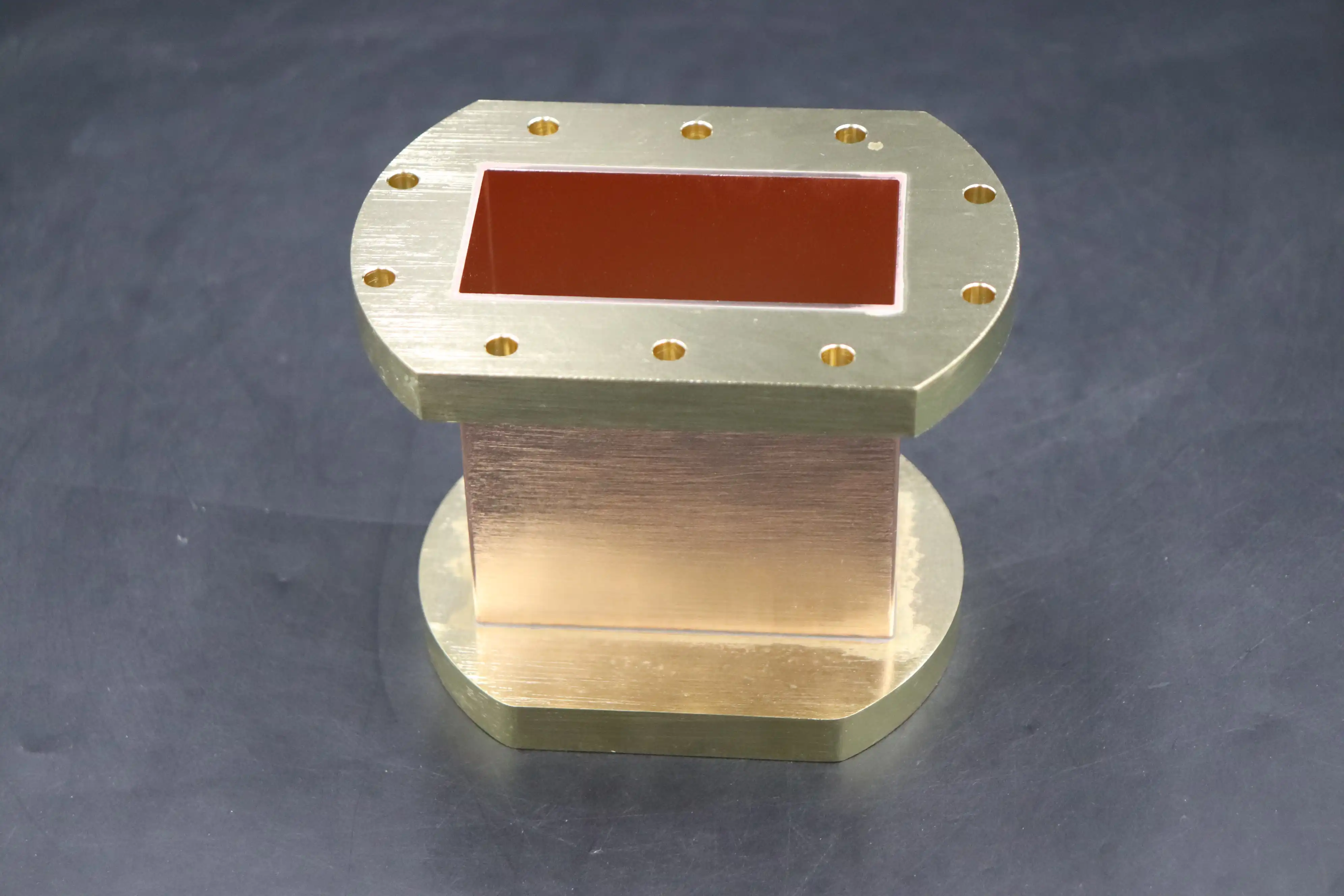
The foundation of successful radar level meter installations begins with understanding how Waveguide Tube design directly impacts measurement accuracy and signal integrity. When radar level meters are installed directly inside tanks without proper guidance systems, the microwave signals scatter unpredictably, creating false echoes and unreliable readings that compromise process control and safety protocols. A properly engineered Waveguide Tube acts as a focused transmission path that guides electromagnetic waves from the radar antenna to the liquid surface and back, eliminating interference from tank internals, agitators, and foam layers. The tube essentially creates a controlled measurement environment within the chaotic conditions of industrial vessels. Material selection forms the cornerstone of waveguide tube manufacturing, with carbon steel and stainless steel emerging as the optimal choices due to their electromagnetic shielding properties and structural durability. For applications involving corrosive media or specialized environments like ball tanks, stainless steel becomes mandatory to prevent degradation that would compromise both structural integrity and signal transmission characteristics. The manufacturing process demands precision that extends beyond simple tube fabrication. Waveguide tubes must be constructed as single-piece units whenever possible to maintain signal continuity and prevent impedance mismatches that generate false echoes. When extensions become necessary due to tank depth requirements, the outer jacket welding method must be employed with gaps maintained below one millimeter to ensure seamless signal propagation. The inner wall surface quality critically affects performance, as any burrs, weld beads, or surface irregularities create reflection points that interfere with the true echo signal from the liquid surface. Advanced manufacturing facilities like those at Advanced Microwave Technologies Co., Ltd employ strict quality control measures to guarantee smooth interior surfaces throughout the entire Waveguide Tube length, maintaining the signal path integrity essential for accurate radar level measurement.
Material Selection and Structural Requirements
The choice between carbon steel and stainless steel Waveguide Tube construction depends on specific application parameters including media chemistry, temperature conditions, and environmental exposure factors. Carbon steel offers cost advantages for non-corrosive applications operating at moderate temperatures, while stainless steel provides superior corrosion resistance and longevity in harsh chemical environments. The electromagnetic properties of both materials effectively contain and guide microwave signals, preventing external interference from affecting measurement accuracy. Wall thickness specifications must balance structural strength requirements with electromagnetic transmission efficiency, with standard, thin-wall, and heavy-wall options available to match different operating pressures and mechanical stress conditions. Advanced Microwave Technologies Co., Ltd manufactures Waveguide Tube products in sizes ranging from WR2300 to WR10, accommodating frequency ranges from 0.5 GHz to 110 GHz to serve diverse industrial applications. The company's extensive experience with waveguide assemblies and coaxial components ensures that each tube meets precise dimensional tolerances critical for radar level meter performance. Material selection also considers thermal expansion characteristics, as temperature fluctuations in process vessels can cause dimensional changes that affect signal propagation if not properly accounted for during the design phase.
Opening Design and Pressure Equalization
One of the most critical yet often overlooked aspects of Waveguide Tube design involves the strategic placement and sizing of pressure equalization openings along the tube length. These cross-sectional openings serve dual purposes: maintaining equal liquid levels inside and outside the waveguide tube while preventing measurement errors caused by pressure differentials. The opening dimensions must be carefully calculated based on the waveguide tube diameter to achieve optimal performance without compromising structural integrity or creating turbulence that could affect the radar signal. Engineering experience has established empirical relationships between Waveguide Tube diameter and required opening area. For DN125 diameter tubes, the total opening area should approximate 0.1 square meters, distributed at appropriate intervals along the tube length. As tube diameter increases to DN200, DN250, and DN300, the corresponding opening areas should expand to 0.4, 0.8, and 1.2 square meters respectively to maintain proper pressure equalization and liquid level consistency. These openings must be positioned at regular intervals to prevent localized pressure accumulations that could create measurement dead zones or false echo generation. The spacing between openings typically ranges from 300 to 500 millimeters depending on tube diameter and application-specific factors such as liquid viscosity and turbulence intensity. Opening geometry also affects performance, with cross-shaped or circular patterns preferred over linear slots that might compromise structural strength. The edges of each opening must be deburred and smoothed to prevent interference with the electromagnetic field propagating through the Waveguide Tube. Advanced manufacturing techniques ensure that opening dimensions maintain tight tolerances across production runs, with quality control systems verifying each tube meets specified parameters before delivery to customers.
Installation Guidelines and Technical Specifications
Proper installation of Waveguide Tube assemblies requires attention to positioning, alignment, and integration with the radar level meter system. The tube must be positioned to avoid interference from tank inlets, agitators, and other internal structures that could create signal reflections or physical obstructions. Vertical alignment proves critical for optimal performance, as even slight deviations from true vertical can cause the radar probe to contact the tube wall, generating false echoes that compromise measurement accuracy. Advanced Microwave Technologies Co., Ltd provides comprehensive installation support, leveraging their 24-meter Microwave Darkroom testing facility to validate tube performance before field deployment. The bottom end of the Waveguide Tube should extend to at least 50 millimeters below the lowest required measurement point while maintaining a minimum 30-millimeter clearance from the tank bottom to prevent signal blockage and ensure proper liquid circulation. The upper end must account for the radar level meter's dead zone specifications, typically extending beyond the highest expected liquid level by the manufacturer-specified distance. For tanks with significant liquid level fluctuations or foam generation, the waveguide tube length should incorporate additional safety margin to ensure the radar antenna remains in clean vapor space under all operating conditions.
Diameter and Length Specifications
Waveguide Tube diameter selection directly impacts the types of radar probes that can be accommodated and the quality of signal transmission achieved. For single-rod guided wave radar level meters, minimum tube internal diameter should be 50 millimeters to prevent the probe from contacting the tube walls during thermal expansion or mechanical vibrations. Double-rod configurations require larger diameters, with 80 millimeters representing the practical minimum for reliable operation. Cable-type probes offer flexibility for deeper tanks, but the Waveguide Tube diameter must still accommodate the cable's natural tendency to drift within the tube during liquid level changes or temperature variations. Advanced Microwave manufactures Waveguide Tube products with lengths up to 3 meters as standard offerings, with custom lengths available to meet specific tank depth requirements. The company's expertise in waveguide assemblies ensures that extended lengths maintain consistent internal dimensions and surface quality throughout their entire span. For applications requiring multiple tube sections, the connection methodology becomes critical to prevent signal degradation at the joints. Outer jacket welding techniques with precision gap control maintain electromagnetic continuity across connections, while internal alignment fixtures ensure that the joined sections form a straight, continuous pathway for the radar signal. Material choices between aluminum and copper affect both performance characteristics and cost considerations. Copper provides superior electrical conductivity and signal transmission properties, making it preferred for high-frequency applications and precision measurement requirements. Aluminum offers weight advantages and cost benefits for moderate-frequency applications where its slightly higher signal attenuation remains within acceptable limits for the measurement range required. Advanced Microwave's ISO 9001:2015 certification ensures that both material options meet stringent quality standards throughout the manufacturing process.
Integration with Radar Level Meter Systems
The interface between the Waveguide Tube and the radar level meter requires careful attention to ensure proper sealing, electromagnetic continuity, and mechanical stability. Thread connections must be compatible with standard radar level meter flanges, with custom adapter plates available for non-standard configurations. Gasket materials should be selected based on process media and temperature conditions, ensuring a vapor-tight seal that prevents media from entering the space between the antenna and the waveguide tube interior wall. This sealed configuration prevents false echoes from material buildup on the antenna while maintaining the clean measurement environment that makes waveguide tube installations so effective. The radar probe must be positioned concentrically within the Waveguide Tube to maintain consistent clearance from all walls throughout its length. Insulating brackets or centering devices may be required for cable-type probes to prevent contact with the tube walls during operation. These centering mechanisms must be designed to avoid creating electromagnetic reflections that could interfere with the level measurement signal. Advanced Microwave's engineering team provides application-specific guidance on probe positioning and centering solutions based on the radar level meter model and operating conditions encountered in each installation. Grounding considerations affect both safety and measurement performance, with proper grounding preventing static charge accumulation that could create electrical interference or pose explosion risks in hazardous area classifications. The Waveguide Tube should be electrically bonded to the tank structure through the mounting flange, with supplementary grounding straps installed if the flange connection incorporates insulating gasket materials. Process connections must maintain electromagnetic shielding continuity while accommodating thermal expansion and mechanical stresses encountered during normal operations.
Optimization Strategies for Challenging Applications
Certain industrial applications present unique challenges that require specialized Waveguide Tube configurations beyond standard designs. High-viscosity media with measurements up to 500 centistokes demand careful consideration of opening sizes and spacing to ensure proper liquid level equalization without allowing media to accumulate on the tube's internal surfaces. Media exhibiting foaming tendencies benefit from extended Waveguide Tube heights that position the radar antenna well above the foam layer, with the tube serving to focus the signal through the foam to reach the actual liquid surface beneath. Turbulent conditions created by agitators or rapid filling operations necessitate robust tube designs with reinforced wall thicknesses and secure mounting arrangements that prevent vibration-induced measurement errors. Temperature extremes affect both the Waveguide Tube materials and the electromagnetic properties of the media being measured. High-temperature applications may require thermal isolation between the radar transmitter electronics and the process vessel, with extended neck designs providing sufficient distance for temperature reduction before the signal reaches sensitive electronic components. Cryogenic applications present opposite challenges, with thermal contraction affecting dimensional stability and material brittleness concerns requiring careful material selection. Advanced Microwave's experience across diverse industries including aerospace, defense, and satellite communications provides valuable insights for optimizing Waveguide Tube designs to perform reliably under extreme operating conditions.
Handling Low Dielectric Constant Media
Media with dielectric constants below 1.5 present particular challenges for radar level measurement, as the weak signal reflection from the liquid surface can be difficult to distinguish from background noise and false echoes. Waveguide Tube installations improve performance with low dielectric materials by focusing the electromagnetic energy along a defined path, increasing the signal strength that reaches the liquid surface and enhancing the return signal amplitude. The confined geometry of the Waveguide Tube also reduces the number of alternative reflection paths that could generate competing echo signals, making it easier for the radar signal processing algorithms to identify the true liquid level echo. For extremely low dielectric applications, specialized Waveguide Tube configurations may incorporate conductive coatings or surface treatments that enhance electromagnetic focusing effects without introducing reflection points that would compromise measurement accuracy. Advanced Microwave's testing capabilities, including their Antenna Plane Near and Far Field Measuring Recombination Chamber operating across 0.5 to 110 GHz, enable comprehensive validation of waveguide tube performance with various dielectric constant media before field installation. This testing identifies potential issues and optimizes tube geometry for specific application requirements, ensuring reliable measurement performance from initial startup through years of continuous operation. The company's RoHS compliance and environmental management systems certified to ISO 14001:2015 ensure that all materials and manufacturing processes meet global environmental standards while delivering the performance characteristics demanded by critical industrial applications. Quality assurance procedures validated under ISO 9001:2015 provide confidence that every Waveguide Tube meets design specifications and will perform reliably in its intended application environment.
Maintenance and Long-Term Performance Considerations
Successful Waveguide Tube installations require minimal maintenance when properly designed and installed, but periodic inspection ensures continued optimal performance throughout their service life. Internal surface conditions should be verified during planned maintenance shutdowns, with any material accumulation or corrosion promptly addressed to prevent signal degradation. The opening areas must remain clear of blockages that could prevent proper pressure equalization, with cleaning procedures established based on the specific media characteristics and operating conditions encountered in each application. Radar level meter calibration procedures should account for the Waveguide Tube installation, with reference measurements taken at known liquid levels to verify that the system accurately translates signal travel time into liquid level readings. Advanced diagnostic tools available in modern radar level meters enable comparison of current echo profiles against baseline measurements captured during initial commissioning, providing early warning of developing issues before they affect measurement accuracy. Advanced Microwave's technical support team assists customers with troubleshooting and optimization, leveraging their extensive experience with waveguide assemblies and measurement systems to resolve performance issues and maximize system reliability. Long-term performance monitoring tracks trends in signal strength, measurement stability, and system response characteristics to identify gradual degradation that might indicate emerging maintenance needs. Process changes that affect media properties, temperature ranges, or operating pressures may necessitate reevaluation of the Waveguide Tube configuration to ensure continued optimal performance. The company's commitment to customer success, demonstrated through ISO 45001:2018 occupational health and safety management systems, extends to providing ongoing technical support and upgrades as application requirements evolve over time.
Conclusion
Optimizing Waveguide Tube design for radar level meter installations requires careful integration of material selection, dimensional specifications, opening design, and installation practices to achieve reliable measurement accuracy under demanding industrial conditions.
Cooperate with Advanced Microwave Technologies Co., Ltd.
Advanced Microwave Technologies Co., Ltd stands as your trusted China Waveguide Tube manufacturer, delivering High Quality Waveguide Tube solutions backed by over 20 years of microwave technology expertise. As a leading China Waveguide Tube supplier and China Waveguide Tube factory, we offer competitive Waveguide Tube prices with Waveguide Tube for sale in configurations from WR2300 to WR10, supporting frequencies up to 110 GHz. Our China Waveguide Tube wholesale programs provide customized solutions with materials including aluminum and copper in standard, thin-wall, and heavy-wall thicknesses up to 3 meters length. With ISO 9001:2015, ISO 14001:2015, and ISO 45001:2018 certifications, our 24-meter Microwave Darkroom enables precision testing ensuring every product meets exacting performance standards. Contact our expert team at craig@admicrowave.com to discuss your waveguide tube requirements and receive technical consultation for your radar level measurement applications.
References
1. Chen, Y., & Wang, L. "Guided Wave Radar Technology in Industrial Level Measurement Applications" Journal of Process Control Engineering, Vol. 45, No. 3, 2023.
2. Thompson, R.J. "Waveguide Design Principles for Microwave Transmission Systems" IEEE Transactions on Microwave Theory and Techniques, Vol. 68, No. 12, 2022.
3. Martinez, A., & Schmidt, K. "Optimizing Radar Level Measurement in Challenging Process Conditions" Instrumentation Technology Review, Vol. 31, No. 2, 2024.
4. Anderson, P.E., & Liu, H. "Material Selection and Manufacturing Standards for Industrial Waveguides" Materials Science in Measurement Systems, Vol. 29, No. 8, 2023.
YOU MAY LIKE
 VIEW MORELog Periodic Antenna
 VIEW MORESlotted Waveguide Array Antenna
 VIEW MOREOpen Boundary Dual Linear Polarization Four Ridged Horn Antenna
 VIEW MOREConical Dual circular Polarization Horn Antenna
 VIEW MORELadder Membrane Conical Dual circular Polarization Horn Antenna
 VIEW MOREDual Linear Broadband Dual Circular Polarization Horn Antenna
 VIEW MOREConical Linear Polarization Horn Antenna
 VIEW MOREPlanar Spiral Antenna
