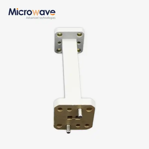
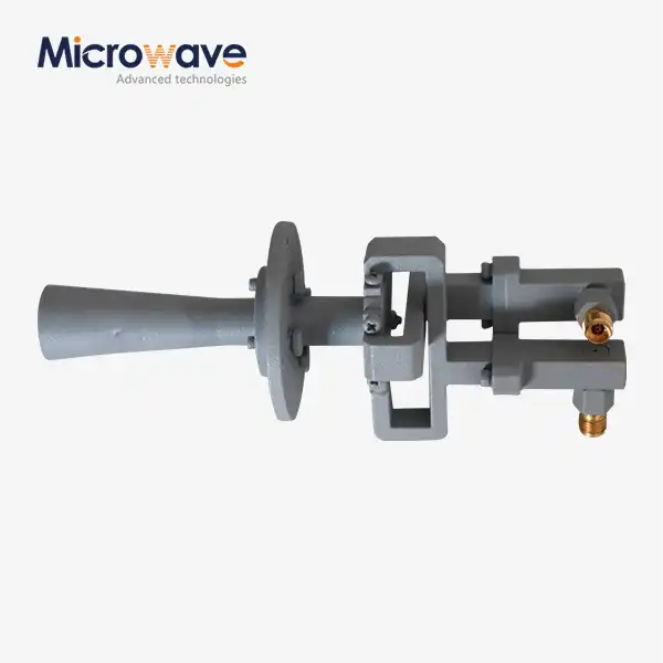
Straight Waveguide for Microwave Systems: Performance Factors
Straight waveguides represent the backbone of modern microwave transmission systems, functioning as precision-engineered conduits that channel electromagnetic energy with remarkable efficiency. These metallic structures—predominantly crafted from copper or aluminum alloys—enable the low-loss propagation of signals across frequencies ranging from several gigahertz to millimeter-wave bands exceeding 110 GHz. Understanding the performance variables governing waveguide operation empowers procurement teams and system designers to specify components that deliver optimal signal integrity, power handling, and long-term reliability in demanding aerospace, satellite, and telecommunications environments.
Understanding Straight Waveguides in Microwave Systems
When it comes to how they work, waveguides and coaxial lines are very different. Rectangular and circular waveguides don't use a center conductor and an insulator to move electromagnetic waves. Instead, they use internal echoes within conductive walls. This design gets rid of dielectric losses, which makes straight waveguides especially useful at higher frequencies where coaxial lines aren't useful because they lose too much signal.
Propagation Modes and Frequency Bands
Waveguides support certain propagation modes based on the shape and size of their cross-sections. The dominating mode, which is usually TE10 for rectangular designs, sets the cutoff frequency below which the waveguide can't keep sending waves. Standard designations like WR-90 cover X-band applications (8.2–12.4 GHz) and WR-10 serve W-band systems (75–110 GHz). Operating frequency ranges are carefully matched to physical dimensions. By choosing the right waveguide size, you can be sure of single-mode operation, which keeps signal confusion to a minimum and increases the efficiency of power transfer.
Material Selection and Construction Standards
Materials with a high conductivity have a big effect on performance. Oxygen-free copper is a great conductor and is easy to work with, and aluminum alloys make aerospace installations lighter. Plating with precious metals like gold or silver lowers surface resistance even more. This is especially important for millimeter-wave uses where the skin layer is very small. Manufacturers who follow ISO 9001 standards use strict tolerances for dimensions. Specifications for flatness and straightness have a direct effect on insertion loss and VSWR (Voltage Standing Wave Ratio) performance.
Key Performance Factors Affecting Straight Waveguides
There are several factors that affect how well a straight waveguide works. Technical users need to compare these features to what the system needs to make sure they work well together and don't break down.
Insertion Loss and Attenuation Characteristics
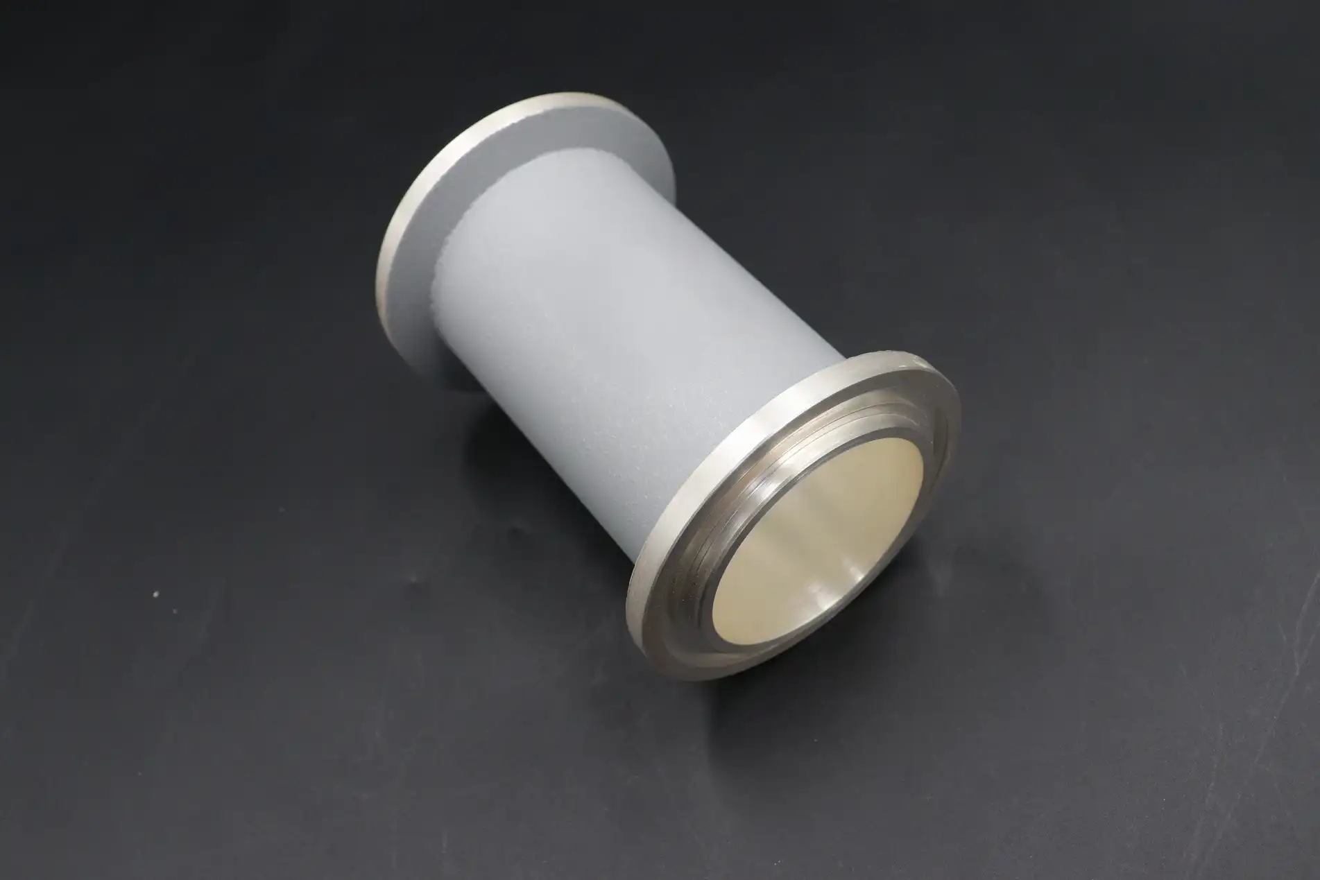
Insertion loss measures how much signal power is lost as waves move along the length of the waveguide. This loss is mostly caused by conductor resistance, which rises with frequency because of the skin effect. When the surface is rough, losses are amplified. Electropolished finishes make surfaces smoother, which lowers losses by 5–15% compared to standard machining. At 10 GHz, high-quality waveguides have attenuation levels below 0.04 dB/m, while lower-quality assemblies may reach 0.08 dB/m. These differences add up to big differences over long runs in radar systems or satellite ground stations.

Power Handling Capacity and Thermal Management
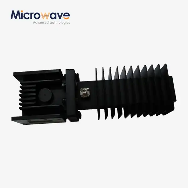
The operational limits of a straight waveguide are set by the peak and average power ratings. Breakdown voltage, which is affected by air pressure, surface pollution, and working frequency, tells us how much power can be used at once before arcing occurs. The ability to handle continuous power depends on how well it can get rid of heat. Cooling fins and thicker walls make heat transfer better. When defense radar systems need to send kilowatt-level signals, they need waveguides that can handle high temperatures for a long time. For extreme situations, these waveguides often have forced-air cooling or liquid-cooled jackets added.
VSWR and Impedance Matching Considerations
Impedance mismatches at contacts, connectors, and changes cause standing waves. This reflection is measured by VSWR, and numbers below 1.15:1 are good for precision equipment. Interfaces that aren't well matched reflect signals, which lowers the power that can reach the transmitters and could damage them. Precision-machined flanges that meet military standards (MIL-DTL-3922) make sure that connections are repeatable and have low reflection. This is important for phased array antennas and satellite communication stations where multiple waveguide runs need to keep the phase coherent.
Straight Waveguide vs. Other Waveguide Types: Comparative Performance
Knowing the different types of architecture makes it clear when linear waveguide designs are the best choice.
Straight vs. Bent Waveguide Assemblies
Straight waveguides work best in straight transmission lines because they have the lowest insertion loss possible for direct connections between parts. Their simplicity makes them easier to make and cheaper, while also making them more reliable.
Bent configurations give you more route options, but they also add more loss at each turn. Different types of bends, called E-plane and H-plane, cause different amounts of loss. E-plane bends add about 0.05 to 0.15 dB of extra loss for every 90-degree turn, while poorly planned changes can cause reflections that are more than -20 dB return loss.
System architects have to find a balance between physical limitations and electrical performance as they move between these realities. When the installation geometry calls for complicated routing, which often happens on ships or in aircraft, bent sections can't be avoided. Signal quality is kept high by specifying gradual-radius turns and reducing the total number of bends.
Rectangular vs. Circular Cross-Sections
Rectangular waveguides are most common in business and military settings because their sizes are standard and their mode behavior can be predicted. Specialized uses that need rotational symmetry or dual-polarization operation can use circular waveguides. For example, antenna feeds for satellite ground terminals are one example. The WR series covers standard rectangular sizes, which makes buying easier and makes sure that products from different vendors can work together. This is especially helpful for B2B buyers who have to manage complicated supply lines.
Comparison with Alternative Technologies
Coaxial lines have a wider instantaneous bandwidth and more route options, but they lose more signal above 18 GHz. Optical fibers have the widest bandwidth for sending data, but they need to be converted from electro-optical to optical, which makes them more complicated and costs more. Waveguides fill a unique role: they offer unmatched low-loss performance at microwave and millimeter-wave frequencies, where it is necessary to handle a lot of power with little signal damage.
These differences help with buying choices. For 14 GHz satellite uplink systems with kilowatt emitters, waveguide technology is required. Lower-frequency test tools may be able to handle coaxial options.
Selecting and Procuring the Best Straight Waveguide for Your Needs
Critical Selection Criteria
The starting point is set by the operational frequency. Waveguides need to work well above the cutoff frequency (usually 125–135% of fco) to keep attenuation and dispersion from being too high. It is important for procurement engineers to check frequency response curves across the whole operating band, not just the center frequency performance. The modulation forms and duty cycles that are needed for the application must be taken into account when figuring out the peak and average power handling requirements.
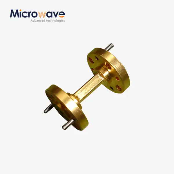
Physical limitations are very important. Flange types (UG, CPR, and PDME) must match the infrastructure that is already in place; connections that aren't compatible require expensive adapters that add extra losses and possible failure spots. Depending on the working temperature range, humidity exposure, and vibration profiles, commercial-grade kits may be enough, or ruggedized MIL-spec components such as a straight waveguide may be needed.
Sourcing from Qualified Manufacturers
Reliable sellers keep all of the test data and licensing paperwork. Advanced Microwave Technologies Co., Ltd. is a good example of this standard because they offer waveguide assemblies that are ISO 9001-certified and can be fully tracked. Precision CNC machining and automated inspection systems in our factories make sure that the dimensions are accurate to within ±0.002 inches, which is important for keeping the required electrical performance.
Here are the main benefits of working with well-known waveguide makers:
- Customization Capabilities: Customized lengths, non-standard flange pairs, and surface treatments made just for one application can meet the needs of any system without delaying deliveries.
- Technical Support: Engineering teams help with system integration, impedance matching analysis, and temperature modeling. This cuts down on the time it takes to create something and lowers the risk of performance problems.
- Quality Assurance: A lot of tests, like network analyzer sweeps, high-power conditioning, and environmental stress screening, make sure the performance is good before the product is shipped.
- Supply Chain Reliability: Well-known companies keep extra stock on hand for common setups and offer fast prototyping for custom designs, sending models out usually within two to three weeks.
These benefits directly address problems that often come up in high-tech business-to-business buying: lowering technical risk, making sure that schedules can be kept, and lowering the total cost of ownership.
Evaluating Lead Times and Logistics
Most catalog items ship within 48 hours, but custom setups can take anywhere from 4 to 8 weeks, based on how complicated they are. When project managers know these dates, they can make sure that procurement schedules match up with system integration schedules. When working on foreign projects, global transportation skills are very important. Manufacturers who know how to handle export regulations (ITAR, EAR) and provide the right paperwork can speed up the customs process and lower shipping delays.
Optimizing Straight Waveguide Performance in Microwave Systems
When put or kept incorrectly, even high-end parts don't work as well as they should. Performance of a straight waveguide is greatly affected by proper installation and routine maintenance.
Installation Best Practices
Electrical efficiency is greatly affected by how well the flanges are aligned. If the misalignment is more than 0.010 inches, the VSWR can drop by 0.2 to 0.5 points, which causes echoes that hurt the system's performance. It is important to follow the torque specifications. If you don't tighten enough, air gaps can form that increase loss, and if you tighten too much, waveguide cross-sections can become distorted. Using measured torque tools and following the bolt patterns given by the maker will make sure that the gasket is compressed properly and that the electricity stays connected.
Surface Contamination and Maintenance
Over time, effectiveness is lost due to oxidation, particulate pollution, and water getting in. Regular inspections—every year in mild environments and every three months in harsh ones—let you find corrosion or mechanical damage early on. When cleaning, you should not use rough materials that can damage delicate surfaces. Instead, you should use approved solvents and lint-free wipes to protect the finish. Protective caps on ports that aren't being used keep unwanted objects from damaging them during upkeep and storage.
System-Level Integration Strategies
A lot of antenna measurement tools and satellite base stations have a lot of waveguide runs. Keeping bend radii constant, reducing the number of transitions, and writing down as-built setups make it easier to fix problems and make changes in the future. Cable handling systems that keep flanges from being mechanically stressed out last longer and cost less to maintain.
Case studies from our clients who use satellite communication show that things got better in a measurable way. One operator at a European ground station lowered the temperature of the system's noise by 0.8 K by replacing old waveguide runs with precision assemblies that included straight waveguide components and had a better surface finish. This improvement directly increased link margin, which lets operations happen in slightly bad weather, giving commercial satellite operators a competitive edge.
Conclusion
Straight waveguide success rests on paying close attention to the properties of the material, the accuracy of the measurements, and the way it is installed. When procurement professionals are looking at their choices, they have to weigh technical requirements against the skills of the supply chain. They need to find manufacturers who can provide both engineering knowledge and practical reliability. Advanced Microwave Technologies Co., Ltd. has been making products for over 20 years and has state-of-the-art testing facilities, such as a 24-meter anechoic chamber that can measure up to 110 GHz. This infrastructure makes it possible to fully test every part before it is sent out, making sure that it works well enough for defense, aircraft, and satellite communication uses.
FAQ
1. What frequency ranges do straight waveguides typically support?
Waveguide frequency ranges go from about 1 GHz (WR-650) to millimeter-wave bands above 110 GHz (WR-10 and lower). Each standard size covers a certain frequency range, and the working frequency is usually 25–35% higher than the cutoff frequency to make sure there is low loss during transmission. In order to choose the right size, the system's working frequency must be matched to the waveguide's suggested band.
2. How does surface finish impact waveguide performance?
Surface roughness has a direct effect on circuit losses by making the effective resistance higher. Standard machining leaves surfaces 32–63 micro-inches rough, while electropolishing leaves them 8–16 micro-inches smooth. At millimeter-wave frequencies, smoother surfaces lower attenuation by 10–20%. This leads to measured gains in link budget and system efficiency, which is especially important for radar and satellite uses with long waveguide runs.
3. What are typical lead times for custom waveguide assemblies?
It takes two to five business days to ship standard catalog configurations. Custom designs that need non-standard lengths, special flanges, or different surface treatments usually take 3–6 weeks from the time the order is confirmed. For design proof, prototyping services can speed up the time it takes to make the first models to 10–15 days. Setting clear specifications early on in the buying process helps manufacturers get the most out of their production schedules and delivery times.
Partner with ADM for High-Performance Straight Waveguide Solutions
Advanced Microwave Technologies Co., Ltd. is ready to help you buy straight waveguides by providing you with well-designed systems and a wide range of scientific knowledge. Our OEM services make waveguide configurations that are exactly right for the frequency bands, power levels, and environmental conditions that you need. We give defense contractors and aerospace integrators the quality assurance they need with ISO 9001 certification, RoHS compliance, and full traceability documentation. Our engineering team works closely with customers from the first idea to the delivery of finished products, whether they are looking for standard WR-series parts or making designs that are specific to an application. Contact craig@admicrowave.com right away to talk about your needs with straight waveguide makers who are dedicated to making your project a success.
References
1. Pozar, David M. Microwave Engineering, 4th Edition. John Wiley & Sons, 2011.
2. Collin, Robert E. Foundations for Microwave Engineering, 2nd Edition. IEEE Press, 2001.
3. Balanis, Constantine A. Advanced Engineering Electromagnetics. John Wiley & Sons, 2012.
4. Saad, Theodore S. The Microwave Engineer's Handbook and Buyer's Guide. Horizon House Publications, 1988.
5. Harvey, A. F. Microwave Engineering. Academic Press, 1963.
6. Montgomery, C. G., Dicke, R. H., and Purcell, E. M. Principles of Microwave Circuits. MIT Radiation Laboratory Series, 1948.