Why Elliptical Microwave Waveguides Beat Rigid in Long-Haul Runs?
When it comes to sending microwaves over long distances, elliptical microwave waveguides do what fixed rectangular and circular waveguides often can't: they allow for flexible paths with little signal loss. Their corrugated elliptical cross-section strikes a perfect balance between being able to bend mechanically and being electromagnetically efficient. This means that you don't need to use multiple flange connections or complicated elbow assemblies, which can cause reflection losses and VSWR degradation. This design benefit directly means fewer installation points, lower upkeep costs, and signal stability that stays the same across tower runs, satellite uplinks, and high-frequency backhaul systems. This mix of performance and usefulness is a clear benefit for procurement teams that are in charge of mission-critical infrastructure.
Understanding Elliptical Microwave Waveguides and Their Advantages
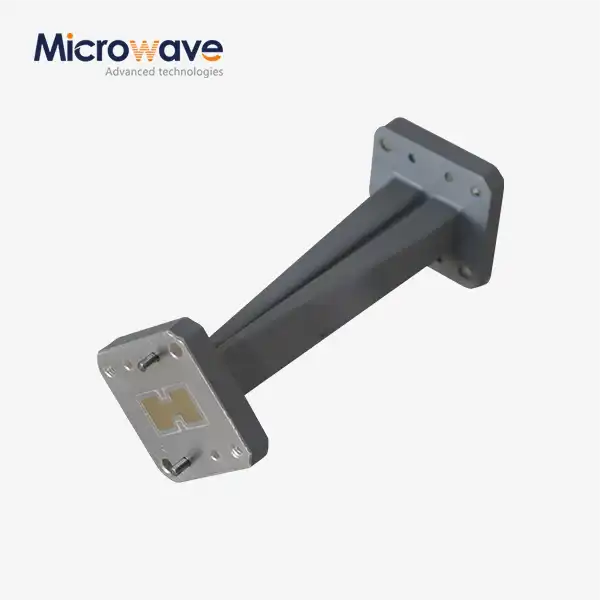
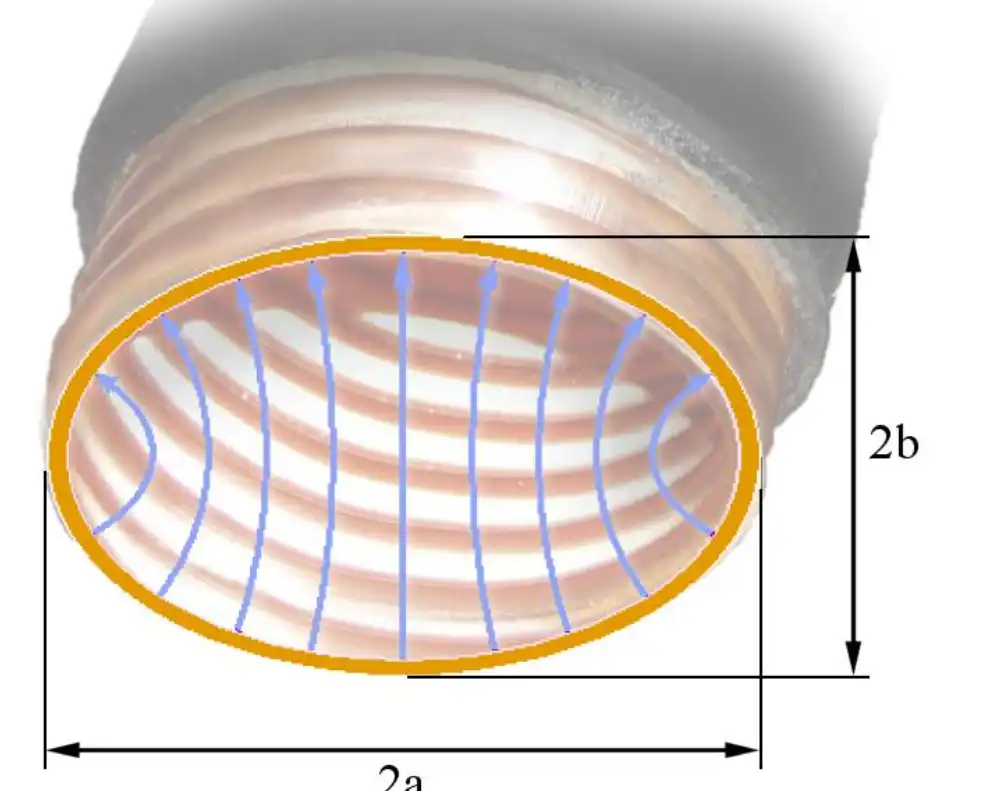
Elliptical microwave waveguides are a special kind of bendable transmission line that were made to send high-frequency microwave and radio frequency signals. Unlike their rigid counterparts, these parts have an elliptical copper or aluminum tube that is corrugated and covered in a UV-resistant polyethylene jacket that is usually black to make it last longer in harsh environments. The form of the ellipse is not random; it serves the main TE11 mode very well, reducing mode conversion losses that happen with other waveguide shapes when they are bent or heated up.
We make elliptical microwave waveguides at Advanced Microwave Technologies Co., Ltd., using precise corrugated copper tubes and strong black polyethylene jackets that are made to last in harsh outdoor conditions. Our products meet the requirements of ISO 9001:2008 and RoHS, which means they meet international standards for quality and environmental friendliness. The corrugation design does two things: it prevents radial crush and lets the material be bent in a controlled way along set E-plane and H-plane radii, all without affecting its electrical performance.
Key Performance Characteristics
There are technical benefits to the elliptical shape that help with problems that come up in long-distance installations. Signal loss rates are much lower than those in large-diameter coaxial cables that work above 6 GHz. They are usually between 0.05 and 0.15 dB per meter, depending on the frequency band and diameter. In many setups, they can handle more than 10 kW of power, which makes them good for high-power broadcast and satellite transmission tasks where managing heat and stopping arcing are very important.
Because the impedances are matched all the way along the waveguide, the VSWR performance is always less than 1.15:1 across all working bands. This level of uniformity gets rid of the reflection spikes that are normal in rigid assemblies with multiple segments that are joined by flanges. In normal setups, the operating frequency runs from 3 GHz to 40 GHz. For millimeter-wave research and next-generation telecom operations, special designs can increase the range to 110 GHz.
Environmental Resilience and Installation Flexibility
The choice of materials for the upper jacket comes from decades of experience in the field. UV-resistant plastic shields the metal core from damage caused by the sun, water, and chemicals that are often found in tower and rooftop installs. Formulations that don't catch fire meet the safety standards for enclosed cable trays and plenum spaces. On the inside, pressurization ports let dry nitrogen or air in to keep the pressure high. This stops condensation, which breaks down dielectrics and causes rust.
Elliptical microwave waveguides are different from rigid ones because they are mechanically flexible. The minimum bend radii are given independently for the E-plane and H-plane positions, which shows how the elliptical cross-section behaves in different directions. Installers can run long sections of cable along uneven paths, around tower legs, and through cable trays without having to join them. When compared to fixed systems that need precise planning ahead of time and custom flange placement, this feature cuts installation time by 40–60%.
Elliptical vs. Traditional Waveguides: A Comparative Analysis
When buying microwave systems, it's important to know the pros and cons of each waveguide type. When it comes to short-run uses, rectangular waveguides are the best because they are easy to make and work well with a single mode. However, their stiffness becomes a problem when routing is complicated. For every 90-degree bend, a precision-machined elbow part with flanged connections is needed. This adds insertion loss, the chance of VSWR spikes, and mechanical stress points that can be damaged by differences in thermal expansion.
While circular waveguides are good for rotational symmetry, they can have problems with mode degeneracy, which means that more than one propagation mode can exist at the same time, distorting the signal. This problem is solved by elliptical microwave waveguides, which break the circular symmetry in a controlled way. This makes a clear dominant mode while still allowing for flexibility. Ridge waveguides make lower-frequency operation longer by using internal structures, but they lose the ability to handle power and make manufacturing more complicated, making them unsuitable for field termination.
Material and Manufacturing Considerations
Copper or aluminum for the corrugated tube? It depends on how well it conducts electricity, how heavy it is, and how much it costs. Because copper is a better conductor than aluminum at the same frequencies, it has 7% less attenuation. This makes it the best choice for long runs where cumulative losses are important. Aluminum is lighter than copper by about a third, which is important for tower-mounted applications where there are limits on how much weight can be put on the structure.
High-frequency efficiency is directly affected by the quality of the surface finish. Our production methods keep the internal surface roughness below 1.6 microns Ra. This means that even at millimeter-wave frequencies, there aren't many ohmic losses. The precise geometry of the corrugations is held to within 0.05 mm, which ensures uniform impedance and expected bending properties. These specs are important because setups in the field can't handle the changes in performance that come from manufacturing errors that are too loose.
Cost-Benefit Analysis for Long-Haul Scenarios
Even though elliptical microwave waveguides cost more per meter at first than rigid rectangular sections, the flexible option is cheaper in the long run (more than 20 meters). It saves time and effort because the flange assembly, alignment, and torque verification compound are no longer needed along the length of the installation. By getting rid of elbows, bends, and transitional parts, you can save money on materials. As a connection point is taken away, a possible failure mode and source of passive intermodulation (PIM) distortion are taken away. This makes the system more reliable.
Continuous waveguide runs get rid of the places where different metals meet at flanges, which are prone to corrosion. This makes maintenance cycles longer. Instead of concentrating at rigid joints, thermal expansion stresses are spread out evenly across the corrugated structure. Because of these operating benefits, the total cost of ownership is lower over the 15 to 20 years that telecom equipment is usually used.
Optimizing Long-Haul Microwave Transmission with Elliptical Waveguides
There are three main problems with sending signals over long distances: increasing loss, effects of dispersion, and managing power when temperatures are high. Each is dealt with by elliptical microwave waveguides, which have their own specific structure and electromagnetic qualities. The low-loss propagation properties come from the best possible current distribution along the corrugated inner surface. The shape guides energy flow efficiently along the tube axis with little contact with the walls.
Putting up telecom towers is a great example of these benefits. Usually, to connect a base transmission station to an antenna array on a 60-meter tower, you would need 12 to 15 rigid waveguide pieces with flanged connections that use standard rectangular guides. For the elliptical microwave waveguide design that is the same, there is only one continuous run with field-terminated connections at each end. The measured VSWR across the system goes from 1.4:1 (multi-section rigid) to 1.12:1 (continuous ellipse), which means that return loss goes down by 0.8 dB and the efficiency of the transmitted power goes up by the same amount.
Real-World Performance Data
Another example of this is satellite earth station uplink systems that work in the Ka band (26.5-40 GHz). High-power amplifiers that put out 500 to 2000 watts must send as much power as possible to the horns with as little loss as possible. Insertion losses for elliptical microwave waveguides rated for these frequencies are 0.12 dB/meter, while they are 0.18 dB/meter for coaxial runs that are the same length. This gives a 2.4 dB advantage over a 40-meter path, which is the same as a 40% rise in effective radiated power. This is a big difference for systems where every decibel affects the link gap and service availability.
Phase stability across changes in temperature
Another important factor for phased array radars and coherent transmission systems is phase stability across changes in temperature. The accordion-like behavior of the curved structure lets it physically expand without changing the transmission delay. For systems that are properly placed, testing shows phase drift of less than 3 degrees over a temperature range of -40°C to +85°C. This meets the requirements for uses like electronic warfare and precise direction-finding.
Installation Best Practices
To get the best performance, you need to follow the installation instructions provided by the manufacturer. When minimum bend radii are not followed, corrugations are crushed, which creates impedance discontinuities that cause reflections and lossy hot spots. When it comes to routing methods in tight areas, E-plane bending usually lets you use smaller angles (250–400 mm) than H-plane orientation (400–600 mm).
During commissioning, the integrity of the pressurization system needs to be carefully looked after. Most of the time, dry air or nitrogen is used to keep waveguide runs at a positive pressure of 5 to 10 PSI. Leak rates below 0.5 PSI per 24 hours are considered acceptable. Alarms that check the pressure let repair teams know when a jacket's seal is broken before water gets inside and hurts the performance. Regular checks of the pressure and preventative reviews of the jacket greatly increase the service life.
Procurement Insights: Choosing and Sourcing the Right Elliptical Microwave Waveguide
The first step in making a technical specification is to list the working parameters, which include frequency band, power levels, environmental exposure, and physical route restrictions. Through cutoff frequency calculations, the frequency range determines the size of the elliptical microwave waveguides. The internal dimensions must allow the intended mode to propagate while blocking higher-order modes. Because thermal dissipation capacity goes up with surface area and thermal conductivity, power needs affect both size and material choices.
There are more factors for judging a supplier than just comparing prices. ISO 9001 certification means that quality management systems have been in place for a while, but procurement teams should check that waveguide validation testing capabilities are up to date. Advanced Microwave Technologies keeps measurement equipment that works from DC to 110 GHz. This lets them check for full swept VSWR, attenuation, and power handling before they ship the goods. When full feed systems need to be tested, our 24-meter microwave darkroom can characterize far-field antennas.
Certification and Compliance Requirements
For defense and aircraft uses, traceability paperwork must go above and beyond what is required by business standards. Material certificates that prove the purity of the copper, the formulas of the jacket compounds, and controls over each production lot are now required by law. RoHS compliance stops the whole supply chain from using lead-based solders and other restricted substances. For each production batch, our certification inventory has reports on the material makeup, data from electrical performance tests, and results from pressure tests.
Customization capabilities
The ability to customize sets competent sellers apart from exceptional partners. Standard catalogue items can be used for a lot of different tasks, but sometimes mission-specific needs call for custom solutions. We change the size of the ellipse, choose different jacket materials for chemical resistance, change the type of flange to make it work with legacy systems, and design custom connectors that fit proprietary interfaces. Technical support includes help with design, installation, and fixing problems in the field when they happen during integration.
Lead Time and Supply Chain Considerations
To plan global logistics, you need to know about production processes and where to put your goods. Standard elliptical microwave waveguide configurations usually ship two to three weeks after an order is confirmed, using stocked tube and connector stock. Depending on how complicated they are, custom specifications take 6 to 8 weeks to set up tools and start production runs. Strategic buyers who are in charge of multiple deployment sites often set up blanket orders with scheduled releases to make sure they have enough inventory and to protect capacity.
We have partnerships with distributors in North America, Europe, and the Asia-Pacific region, which lets us stock regionally and offer localized technical support. This network cuts down on shipping times and makes it easier for foreign projects to go through customs. We support vendor-managed inventory plans for big infrastructure projects, in which materials are staged at customer sites based on project goals.
Conclusion
Elliptical microwave waveguides are better for long-distance microwave transmission because they have lower insertion loss, better VSWR performance, and more placement options than fixed alternatives. Their ribbed design combines mechanical flexibility with electromagnetic accuracy, getting rid of the joints and changes that slow down system performance. The total cost equation favors elliptical solutions for procurement professionals in charge of satellite communications, defense radar systems, or telecom infrastructure. This is because performance, reliability, and installation efficiency all play a part in the success of the project. As the need for higher frequencies grows and systems become more complicated, waveguide technology based on tried-and-true materials and precise engineering will stay the basis of mission-critical RF designs.
FAQ
1. At high frequencies, why are elliptical microwave waveguides better than coaxial cables?
At frequencies above 6 GHz, skin effect losses and dielectric absorption cause coaxial cable attenuation to rise sharply, often by more than 0.5 dB/meter. With an air dielectric and controlled current distribution, elliptical microwave waveguides can lose only 0.08 to 0.15 dB/meter. Power-handling capacity also favors waveguides, which keep coaxial designs from failing due to heat or voltage breakdown in high-power situations.
2. Is it possible to end elliptical microwave waveguides in the field?
Yes, field closure is an important part of the system. Specialized flaring tools make the corrugated end wider so that normal hand tools can be used to join the connection. To use the right technique, you need to get rid of any metal debris, make sure the flare geometry is uniform, and follow the torque specifications. When done right, field-terminated connections have the same electrical performance as factory assemblies.
3. Why does pressurization matter for waveguide performance?
Moisture buildup inside waveguides causes dielectric losses to rise and rust to happen, which lowers the long-term stability. Positive pressure with dry gas stops wet air from getting in through tiny flaws in the jacket. Pressurization also raises the voltage breakdown limits, which allows more power to be used. Monitoring systems let workers know about leaks before they affect performance, which helps with preventative repair plans.
Partner with ADM for Your Elliptical Microwave Waveguide Requirements
Advanced Microwave Technologies Co., Ltd can help you with your important RF infrastructure projects because they have been making specialised products for over twenty years. Our elliptical microwave waveguides solutions are made up of carefully designed corrugated copper tubes and UV-resistant jacketing. They are reliable for use in defence, satellite, and telecom applications. As a well-known company that supplies elliptical microwave waveguides, we can help you with your buying needs by offering quality systems that are ISO 9001-certified, with full testing up to 110 GHz, and the ability to make changes to socket types, materials, and frequency ranges. Our expert team is ready to help with creating specifications, integrating systems, and making quick prototypes. Please email craig@admicrowave.com right away to talk about your project needs and find out how our tried-and-true waveguide technology can improve the performance of your long-distance transmissions.
References
1. Marcuvitz, Nathan. Waveguide Handbook: Electromagnetic Wave Theory and Propagation in Waveguides. Peter Peregrinus Ltd, 1986.
2. Saad, Theodore S. Microwave Engineers' Handbook, Volume 1: Components and Materials. Artech House Publishers, 1971.
3. Ramo, Simon, John R. Whinnery, and Theodore Van Duzer. Fields and Waves in Communication Electronics. John Wiley & Sons, 1994.
4. Baden Fuller, A.J. An Introduction to Microwave Theory and Techniques. Pergamon Press, 1979.
5. Collin, Robert E. Field Theory of Guided Waves. IEEE Press Series on Electromagnetic Wave Theory, 1991.
6. Montgomery, C.G., Robert H. Dicke, and Edward M. Purcell. Principles of Microwave Circuits (MIT Radiation Laboratory Series). McGraw-Hill Book Company, 1948.