





Crossguide Coupler Applications in Microwave Networks
Crossguide couplers represent a sophisticated class of directional couplers used extensively in high-frequency microwave networks, enabling precise power sampling, signal monitoring, and distribution across multiple channels. These waveguide-based components operate by coupling electromagnetic energy between two perpendicular waveguide arms, delivering exceptional directivity and isolation characteristics essential for mission-critical applications. At Advanced Microwave Technologies Co., Ltd, we've witnessed growing demand for these devices across defense radar systems, satellite ground stations, and telecommunications infrastructure, where their ability to maintain signal integrity at frequencies extending beyond 40 GHz makes them irreplaceable for modern RF architectures.
Understanding Crossguide Couplers: Fundamentals and Design Principles
Core Operating Principles
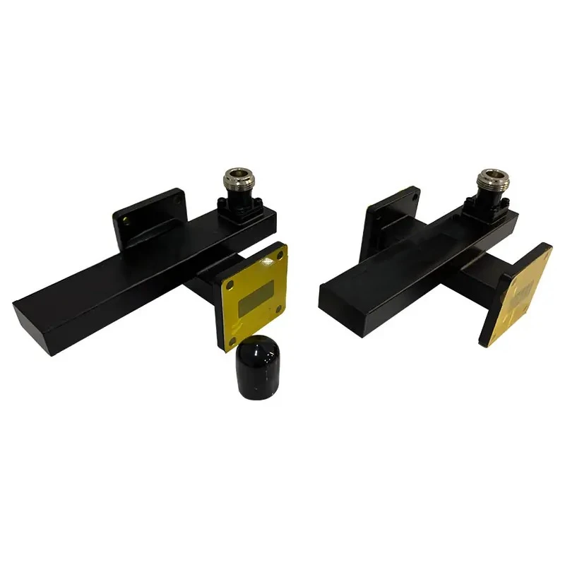
The crossguide coupler works by controlling the electromagnetic coupling between two rectangular waveguides that are placed at right angles to each other. A small, known part of an RF signal that travels through the main waveguide links into the secondary waveguide that is placed at a right angle. Crossguide designs are different from traditional directional couplers because they have a perpendicular structure. This gives better separation between coupled ports and reduces signal reflections. The coupling mechanism depends on carefully designed holes or iris structures placed where the magnetic field strength is highest. This lets controlled energy transfer happen while keeping the waveguide mode purity.
Design Variations and Technical Specifications
When we make things, we see two main types of design configurations. Symmetric crossguide couplers have the same coupling properties no matter which way the signal is going. This makes them perfect for monitoring in both directions in satellite transceivers. Asymmetric designs allow frequency-dependent coupling reactions, which makes them useful for specific tasks like spectrum analysis and multi-band radar systems. Important features include coupling factor (usually between 10 and 30 dB), directivity (often higher than 35 dB), and an operating bandwidth that covers bands from X-band to Ka-band.
Parameter Impact on System Performance
Several factors that are linked together decide how well a coupler works overall. In test equipment, coupling level directly affects measurement accuracy. Tighter coupling pulls out more signal for analysis but adds more insertion loss to the main transmission path. Isolation between output ports is very important in high-power radar systems, where reverse signal leakage could hurt receiver parts that are sensitive to it. Depending on the bandwidth, different types of systems can do different things. Broadband designs can cover octave ranges, while narrowband designs work best for single-frequency applications. Our engineering team at Advanced Microwave Technologies has found that procurement workers get the most out of knowing these trade-offs when choosing components, especially when they have to balance project budgets and performance standards.
Core Applications of Crossguide Couplers in Microwave Networks
Signal Sampling in Telecommunications Infrastructure
In high-capacity data networks, crossguide couplers are very important for tracking. These couplers are used by ground station operators to constantly sample uplink and downlink signals without stopping the main data transfer. Spectrum analysers or power meters can be connected to the linked port to check the quality of the signal, the carrier frequencies, and the accuracy of the modulation in real time. This non-intrusive tracking feature helps improve networks and make sure they are following the rules. It is especially helpful for satellite service providers who are in charge of several receiver channels at the same time.
Power Division in Radar Systems
Crossguide couplers are used to precisely split power across antenna feed networks in both military and civilian radar installations. Many weather monitoring radar systems work all the time in harsh conditions, and the strong mechanical design of waveguide technology helps them do their job. The coupler splits the power being sent between several projecting elements while keeping the phase consistency that is needed for accurate tracking and detecting targets. During receiving, these same parts join weak signals that are reflected from spread-out antenna arrays. This makes the system more sensitive and increases the range of what it can find.
Test and Measurement Applications
Crossguide couplers are often asked for by our aerospace R&D clients to characterise antennas and test components. At Advanced Microwave Technologies, we use precision couplers all over our Antenna Plane Near and Far Field Measuring Recombination Chamber in our own 24 m Microwave Darkroom. These devices let you measure the reaction and send a signal at the same time across a frequency range of 0.5 to 110 GHz, which supports full performance proof. Because waveguide couplers are so repeatable, measurements are always the same across multiple test sessions. This means that our OEM customers can cut down on the number of times they need to calibrate their equipment and speed up the product development process.
Comparing Crossguide Couplers with Alternative Microwave Components
Operational Differences from Circulators and Magic Tees
When designing signal distribution networks, procurement teams often look at more than one type of component. Because they work without reciprocity, circulators isolate ports very well, which makes them perfect for keeping emitter outputs safe from mirrored power. Magic tees are great at splitting power with little insertion loss, but they can't choose the direction of the signal like crossguide designs can. The crossguide coupler is in a special place because it has low insertion loss, high directivity, and the ability to take out small signal samples without putting too much stress on the main transmission line.
Performance Trade-offs and Selection Criteria
Bandwidth properties are very different between these groups of components. Coaxial directional couplers can work across multiple octaves, but they lose more power at millimeter-wave frequencies. Waveguide crossguide implementations have low insertion loss across their design bandwidth, which is usually 15-20% of the fractional bandwidth. This makes them better for fixed-frequency or narrowband applications. Different designs also have different levels of isolation. Crossguide designs often reach 40 dB isolation, while some coaxial options have trouble going above 25 dB, especially as the frequency goes up.
Economic Considerations in Procurement
Price-performance analysis shows how the market works in interesting ways. Standard catalogue crossguide couplers that work with popular frequency bands like X-band or Ku-band have reasonable prices that make them good for modest production volumes. Custom designs that work with specific frequency ranges or need better electrical specifications cost more because engineers have to spend more time and money on tools to make them. From what we've seen at Advanced Microwave Technologies, buyers who get the best total cost of ownership usually work with suppliers early on in the system design process. This lets suppliers optimise components in a way that lowers both unit cost and interface complexity.
How to Select the Best Crossguide Coupler for Your Microwave Network?
Evaluating Critical Technical Parameters
Start the selection process by figuring out the working frequency range, leaving enough room for component errors and changes in the environment. Power handling must be able to handle both average and peak signal levels, taking into account possible standing waves that focus energy at certain waveguide sites. Different types of applications have different coupling accuracy needs. For example, measurement systems in the lab may need a tolerance of ±0.5 dB, while communication tracking can handle a difference of ±1.5 dB. For outdoor locations and mobility platforms, environmental toughness is very important. This means that temperature factors, vibration resistance, and finishes that don't rust according to MIL-STD standards must all be thought about.
Standard Versus Custom Solutions
With off-the-shelf components, wait times are measured in weeks instead of months, which speeds up the buying process. These standard products, including crossguide coupler solutions, can be used in situations where the specifications and frequency bands are commonly asked for. Custom engineering is needed when the system needs to work with unusual frequency combinations, have specific flange configurations for installations with limited space, or have better electrical performance than what is listed in the catalogue. Our OEM services at Advanced Microwave Technologies help with these situations by giving design advice that finds ways to change current systems instead of making completely new ones. This cuts down on development time while keeping the benefits of customization.
Supplier Evaluation and Global Sourcing
An important part of successful procurement is not only knowing what the parts are but also knowing what the suppliers can do. Check to see if the measurement tools you need are available. Test data from makers with vector network analysers that are calibrated to your working frequencies is more reliable. Quality certifications are very important. At Advanced Microwave Technologies, our ISO 9001:2015 certification shows that we have a system for managing quality that includes inspecting incoming materials and validating the final product. Lead times and logistics costs are affected by location, but well-known manufacturers have global distribution networks that make location disadvantages less of a problem. How quickly technical help responds is often the deciding factor when it comes to fixing problems with merging or changing parts to meet changing system needs.
Future Trends and Innovations in Crossguide Coupler Technology
Miniaturization Through Advanced Materials
New substrate-integrated waveguide (SIW) technologies offer cross-guide coupler capabilities in a lot smaller packages. These flat structures use metallized via groups in low-loss laminates to copy the electromagnetic behaviour of waveguides. This makes it possible to integrate them with printed circuit boards. Even though SIW implementations aren't as good at handling power or quality as traditional machined waveguides, this performance gap is getting smaller thanks to progress in material science. This is especially true for millimeter-wave applications where standard waveguide sizes are too small to be useful.
Integration with Adaptive RF Systems
More and more, software-defined radio architectures include smart networks for monitoring and distributing power. In the future, crossguide couplers might have temperature monitors and coupling devices that can be changed electronically built in. This would allow for real-time optimization as the system conditions change. Adaptive couplers like these could fix problems on their own when parts get old, the environment changes, or the operational modes change, without any help from a person. In early phased array radar systems, coupled port signals are already being fed back to beamforming algorithms. This makes closed-loop systems that are always improving the radiation patterns.
Supply Chain and Customization Evolution
Improvements in manufacturing technology have a direct effect on how buying works. Using additive manufacturing for microwave parts, including crossguide coupler components, makes it possible to make quick prototypes of complicated shapes that used to need a lot of machining. We are looking into selective laser melting for unique designs that are made in small quantities at Advanced Microwave Technologies. This could cut the time it takes to make a prototype from eight weeks to less than two weeks. This manufacturing flexibility helps agile development methods, in which both software and hardware are updated. This is especially helpful for research institutions and aircraft projects whose needs are always changing. As these production methods get better, buyers can expect to be able to get more customization options at lower order numbers.
Conclusion
Crossguide couplers are an important part of high-performance microwave networks because they allow accurate signal monitoring and distribution that can't be done with other component technologies. Defence, telecommunications, and research applications continue to use them because of their strong waveguide construction, excellent isolation properties, and long history of reliability in the field. Microwave systems are getting more complicated and using higher frequencies. These basic parts are changing because of new materials and better production techniques, but they still work based on the same electromagnetic principles that made them valuable in the first place. When procurement professionals work with experienced manufacturers, they can get both tried-and-true catalogue solutions and special engineering help for ongoing projects and the move to new technologies in the future.
FAQ
1. What frequency ranges do crossguide couplers typically cover?
Standard crossguide coupler designs work in microwave frequency ranges from about 1 GHz to 110 GHz. Some types are better at working with popular waveguide bands like S-band, X-band, Ku-band, and Ka-band. Each design aims for a specific waveguide size that fits its frequency range. Bandwidth usually ranges from 15 to 20 percent of the center frequency.
2. How does coupling factor affect system design?
The coupling factor tells us how much power is taken from the main gearbox path. When the coupling is tighter (lower dB values like -10 dB), more information is extracted for monitoring, but the main path experiences more insertion loss. Looser coupling (-30 dB) doesn't have much of an effect on main path transmission, but it does provide smaller sample signals, which means that the coupled port needs more sensitive measurement equipment.
3. Can crossguide couplers handle high-power radar applications?
When used in burst radar systems, high-quality waveguide crossguide couplers can handle constant power of several kilowatts and higher peak powers. The power rating is based on the size of the waveguide, the design of the coupling aperture, and, if necessary, the pressurization. Manufacturers set boundaries on both average and peak power, taking into account effects like potential voltage standing wave ratios that focus field strength in certain areas.
Partner with Advanced Microwave Technologies for Your Crossguide Coupler Requirements
With more than 20 years of experience making specialized products, Advanced Microwave Technologies Co., Ltd. is ready to help you buy crossguide couplers. Our wide range of services includes standard waveguide assemblies as well as fully customized OEM solutions for tough aircraft, defense, and telecoms needs. We follow ISO 9001:2015 and RoHS rules in every step of the production process. This makes sure that the quality is always the same and that we are environmentally friendly, which is required by international buying rules. Our 24m Microwave Darkroom lets you check the performance of your system completely from 0.5 GHz to 110 GHz, giving you measurement data that boosts your confidence in the integration. Our engineering team provides responsive technical support from the initial review of the specifications through post-delivery help, whether you need rapid prototyping for research and development programs or mass production for system deployment. Contact craig@admicrowave.com right away to talk to one of our applications engineers about your specific crossguide coupler needs. You can also learn how our manufacturer-direct pricing and ability to accommodate customisations can help you meet project deadlines and budget goals while improving the performance of your microwave network.
References
1. Pozar, David M. "Microwave Engineering, Fourth Edition." John Wiley & Sons, 2012. Chapter 7: Power Dividers and Directional Couplers.
2. Collin, Robert E. "Foundations for Microwave Engineering, Second Edition." IEEE Press, 2001. Section 8.4: Waveguide Directional Couplers.
3. Montgomery, C. G., Dicke, R. H., and Purcell, E. M. "Principles of Microwave Circuits." MIT Radiation Laboratory Series, Volume 8, McGraw-Hill, 1948.
4. Riblet, Henry J. "The Application of a New Class of Equal-Ripple Functions to Some Familiar Transmission-Line Problems." IEEE Transactions on Microwave Theory and Techniques, Volume 12, Issue 4, 1964.
5. Levy, Ralph. "Directional Couplers." Advances in Microwaves, Volume 1, Academic Press, 1966, pp. 115-209.
6. Saad, Theodore S. "Handbook of Microwave Integrated Circuits." Artech House Microwave Library, 1985. Chapter 9: Couplers and Hybrids.
YOU MAY LIKE
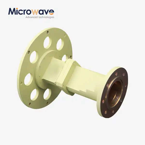 VIEW MORECircular Waveguide Transition
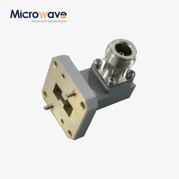 VIEW MORERight Angle Double Ridged WG To Coaxial Adapter
 VIEW MOREWG High Pass Filter
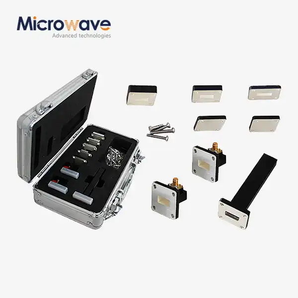 VIEW MOREWaveguide Calibration Kits
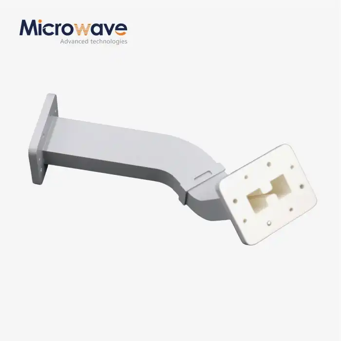 VIEW MOREDouble Ridge Waveguide Bend
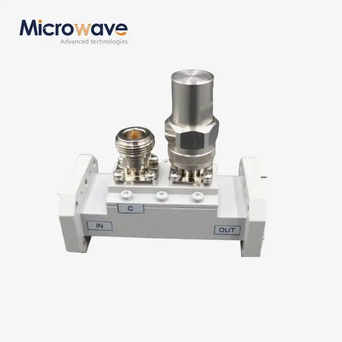 VIEW MOREDouble-Ridged Waveguide Loop Coupler
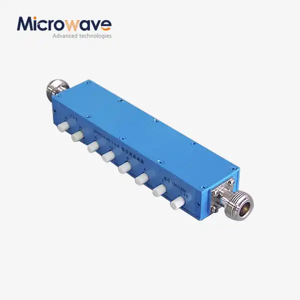 VIEW MORECoaxial Variable Attenuator
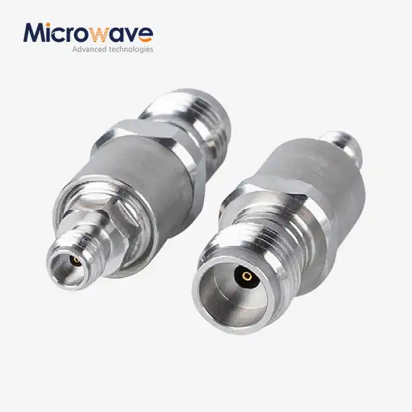 VIEW MORECoaxial Cable Adapter
