Rotary Vane or Flap: Which Waveguide Variable Attenuator Do You Need?
When selecting a waveguide variable attenuator for your microwave or RF system, the choice between a rotary vane and a flap (resistive vane) design is rarely straightforward. Both types control signal amplitude within a waveguide transmission line, but they achieve this through different mechanical principles — and that difference has a direct bearing on measurement accuracy, power handling, and long-term reliability. This guide walks you through the technical distinctions, real application scenarios, and practical procurement considerations so you can make a well-grounded decision.
Understanding Waveguide Variable Attenuators
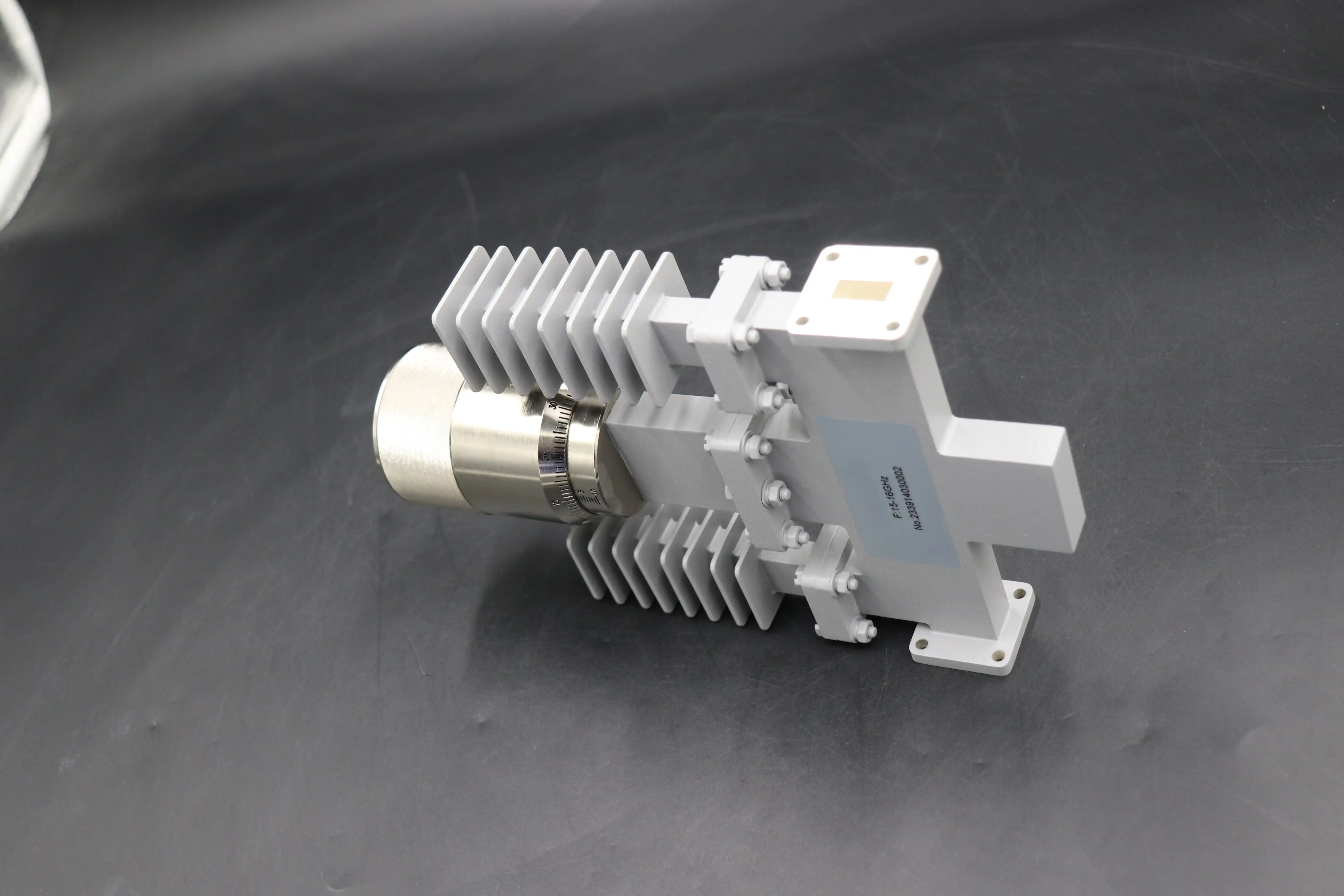
A waveguide variable attenuator is a precise microwave part that changes how strong an electromagnetic signal is as it moves through a hollow metal waveguide. Unlike a set attenuator, it lets you change the level continuously or steplessly, usually from 0 dB to 30 dB or more, without stopping the signal transmission. Putting a resistive or absorptive part inside the waveguide's electric field lowers the signal. More energy is absorbed as the element moves deeper into the field, and the signal amplitude drops in a controlled, repeatable way.

Standard waveguide bands are used by these devices. The WR-90 covers the X-band (8.2–12.4 GHz), the WR-28 the Ka-band (26.5–40 GHz), and the WR-10 the W-band (75–110 GHz). Some of the most important factors that go into buying choices are:
- Attenuation range and accuracy: Precision rotary vane types are accurate to within ±0.1 dB or 2% of the reading over a range of 0 to 60 dB.
- Insertion loss at 0 dB setting: Below 0.5 dB is best to keep the system working well.
- VSWR: A low VSWR (usually less than 1.15:1) reduces reflections that can hurt sources upstream or mess up measurements.
- Power handling: Waveguide versions can handle kilowatts of peak CW power because they are made of air-dielectric material and metals that quickly lose heat. At high frequencies, coaxial versions cannot do this.
In business-to-business settings, these gadgets are necessary for setting up radar, testing satellite links, controlling receiver gain, and automated test equipment (ATE). If you choose the wrong type, you will have trouble measuring, working with delays, and extra upkeep costs.
Rotary Vane vs. Flap Waveguide Variable Attenuators: Technical Comparison
Rotary Vane: High Precision, Consistent Phase Behavior
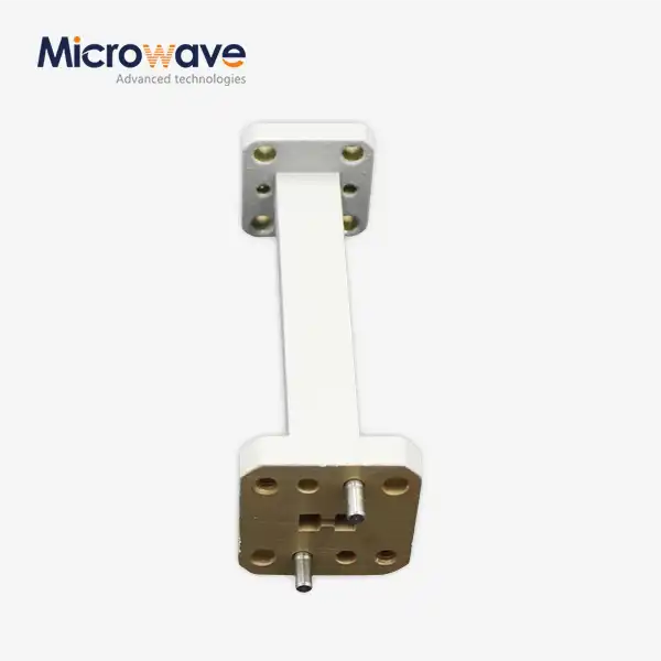
The rotary vane waveguide variable attenuator has three resistive cards inside a waveguide assembly. The outer parts are stable, and the middle piece rotates. There is a clear mathematical link between attenuation and rotation angle. Specifically, attenuation changes as 40 log(cos θ), where θ is the rotation angle. This makes attenuation values that are very repeatable and easy to calculate, with very little phase deviation. Rotary vane designs are instruments that are used for calibration and can be found in metrology labs, vector network analyzer (VNA) setups, and places where satellite payloads are tested. They keep the phase very stable across their attenuation range, which is a very important quality for measuring coherent signals. The VSWR stays close to 1.05:1 across most working bands, and the remaining insertion loss is usually less than 0.5 dB.
Flap Attenuator: Rugged, High-Power Field Use
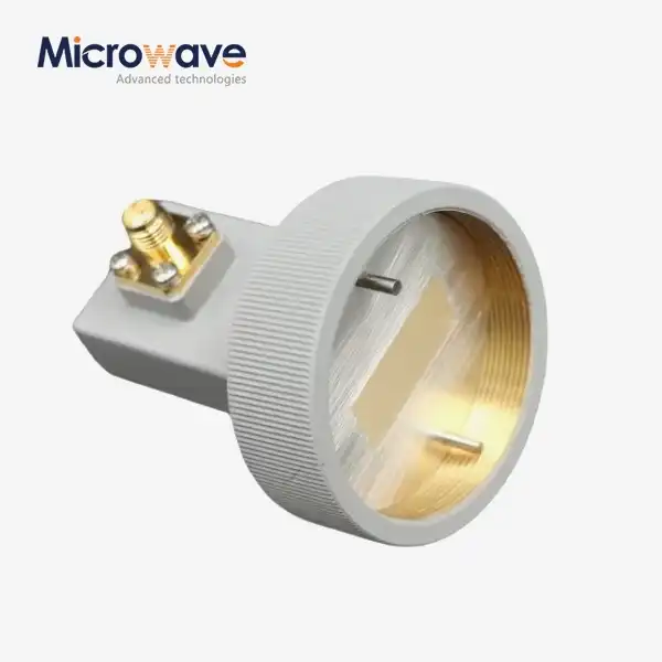
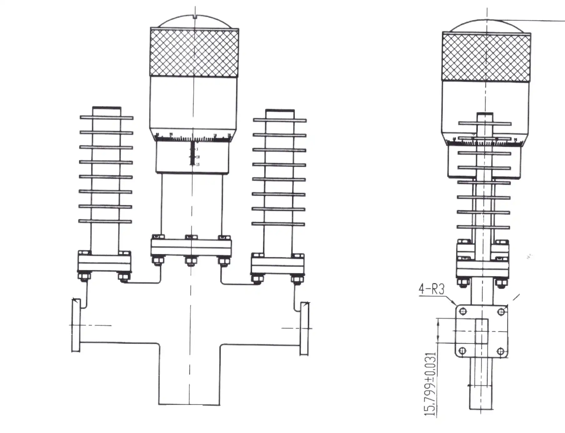
A resistive dielectric vane is inserted into the waveguide aperture through a lengthwise hole to make the flap-type attenuator work. The attenuation increases as the vane goes deeper. Since there is no straight line between vane position and attenuation, micrometer-driven models need a calibration chart to turn mechanical position into dB values. A measured drum scale makes it easier to make changes quickly on direct-reading types. Because they can handle high average and peak power levels, flap attenuators are great for testing transmitters, setting up field communication systems, and pulsed radar systems. Because they have fewer precise parts and are technically simpler, they are easier to service in the field. But as the vane moves in, they cause more phase shift, which is fine for power management but not for measurement chains that depend on phase.
For a straight look at the main differences in performance between the two types, here they are:
- Rotary vane: Attenuation accuracy ±0.1 dB or better; phase shift of almost zero; works with frequencies from X-band to W-band; best for lab-grade precision and vector measurements.
- Flap type: Higher power handling; nonlinear calibration curve; allows for more change in the insertion phase; best for testing high-power transmitters and putting them into use in the field.
- Motorized variants: Both types can come with stepper motors and GPIB, Ethernet, or USB interfaces for ATE integration and sweeping the attenuation remotely using scripts.
These differences in performance make it clear which waveguide variable attenuator belongs in your system. There is no one type that is always better; the right choice relies on the needs of your application.
Decision-Making Guide: Which Waveguide Variable Attenuator Fits Your Needs?
Defense OEMs, satellite operators, research institutions, and contract manufacturers all have different needs for their procurement experts. This is how application context is linked to waveguide variable attenuator choice:
Defense and aerospace system integrators usually choose rotary vane designs for radar calibration chains and EW subsystem testing, where repeatable, traceable attenuation values are a must. Compliance with MIL-DTL-3933 for outdoor sturdiness, which includes high temperatures and vibration, is another condition that these buyers must check with their provider before they buy.
Engineers at satellite ground stations who are testing rain-fade simulation or uplink power control can benefit from rotary vane models, especially motorized ones that can sweep the attenuation automatically while working with software for link budget analysis.
Field communication experts and teams working on high-power transmitters like flap attenuators. The fact that they can handle high CW and pulsed peak power and are easy to service mechanically makes them useful in places where there is not a VNA calibration lab nearby.
Universities and research labs that want to test how well a part works across a range of frequency bands often choose rotary vane attenuators because they have a mathematically known attenuation law and can be used with VNA calibration methods.
Procurement Insights for B2B Buyers
Before placing an order, people in charge of buying things should always check three things: the technical information, the calibration certificate, and the environmental compliance statement (RoHS, MIL-DTL-3933 if needed). The VSWR should be shown on the datasheets for the whole range of attenuation, not just at the highest setting. For high-value or mission-critical orders, it is best to do acceptance testing using VNA inspection to check for insertion loss, return loss, and mechanical smoothness before putting the parts together.
Most well-known makers have lead times of four to eight weeks for precise rotary vane waveguide variable attenuators in standard waveguide bands (WR-90, WR-62, and WR-28). Lead times may be longer if you need custom frequency bands, motorized drive choices, or flange configurations that are not common. When system designers negotiate bulk purchases with a qualified manufacturer, they can lower the cost per unit and ensure priority scheduling, which is a real benefit for handling multi-phase delivery schedules.
Conclusion
Which one you choose between a spinning vane and a flap attenuator relies on what is most important to your system: accurate measurements or strong power handling. Rotary vane designs are perfect for calibration and vector measurement settings because they are very accurate, stable, and have a mathematically predictable waveguide variable attenuator law. Flap designs are long-lasting, can handle a lot of power, and are mechanically simple, making them good for testing in the field and on transmitters. Before you start looking for suppliers, make sure that the datasheets are completely correct, that they are environmentally friendly, and that you know if you need controlled automation. Long-term results are always better when purchasing decisions are based on how the product will be used instead of just price.
FAQ
What is the main functional difference between rotary vane and flap attenuators?
Rotating vane models use a rotation-based attenuation rule that can be predicted mathematically. This gives them more accuracy and less phase shift. Flap types put in a resistive fan in a straight line, which handles more power better but requires nonlinear tuning and more phase variation.
How does the frequency band determine which attenuator to select?
The working band is based on the size of the waveguide: WR-90 for X-band, WR-28 for Ka-band, and WR-10 for W-band. Standard waveguide sizes come in both types of attenuators, but rotary vane models are more often chosen for precise work in higher millimeter-wave bands.
Are motorized versions available for automated test systems?
Yes, motorized waveguide variable attenuators with stepper motors and common control interfaces like GPIB, Ethernet, and USB can be used with ATE to allow automated test scripts to sweep the attenuation remotely.
What maintenance does high-power operation require?
It is best to check the VNA on a regular basis to find insertion loss degradation caused by vane oxidation or contamination. To keep thread seizure and calibration drift from happening, mechanical drives should be checked often to make sure they work smoothly.
Can a waveguide variable attenuator function as a phase shifter?
When a vane is inserted, there is always a small change in phase, but these devices are not designed to control phase. For phase-sensitive uses, you need a phase changer or an attenuation design that does not change with the phase.
Request a Quote from ADM — Your Trusted Waveguide Variable Attenuator Supplier
ADM has been making high-precision microwave parts for over 20 years that work in mission-critical settings like defense radar systems and satellite ground stations. We offer waveguide variable attenuators that are ISO 9001:2015 certified and RoHS compliant. You can customize them to work with both standard and non-standard waveguide bands. Our engineering team is ready to help you find the right solution, whether you need a precise rotary vane model for testing in the lab or a high-power flap design for use in the field. You can get a document, sample, or bulk quote by emailing craig@admicrowave.com.
References
1. Pozar, D. M. — Microwave Engineering, 4th Edition, Wiley, 2011.
2. Collin, R. E. — Foundations for Microwave Engineering, 2nd Edition, IEEE Press, 2001.
3. Montgomery, C. G., Dicke, R. H., & Purcell, E. M. — Principles of Microwave Circuits, MIT Radiation Lab Series, McGraw-Hill, 1948 (reprinted IET, 1987).
4. IEEE Std 315-1975: Graphic Symbols for Electrical and Electronics Diagrams — IEEE, 1975 (reaffirmed 1993).
5. Lavretsky, M. — "Precision Calibration of Rotary Vane Attenuators for Metrology Applications," IEEE Transactions on Instrumentation and Measurement, Vol. 58, No. 4, 2009.
6. MIL-DTL-3933: Detail Specification — Attenuators, Fixed and Variable, Radio Frequency — U.S. Department of Defense, 2003 (revision D).