Why Your Waveguide to Coaxial Adapter Arcs at High Power
When a waveguide to coaxial adapter arcs at high power, it rarely happens without warning signs — elevated VSWR readings, localized heating, or intermittent signal dropout often precede full dielectric breakdown. Arcing occurs when the electric field intensity inside the adapter exceeds the dielectric strength of the medium — whether air, PTFE, or a plated metal surface. At power levels above several hundred watts, even minor structural imperfections, contamination, or impedance discontinuities can initiate ionization and spark discharge. Understanding the root causes is the first step toward protecting your system and choosing the right components from the start.
Understanding Waveguide to Coaxial Adapters and High-Power Arcing
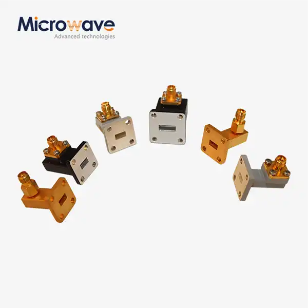
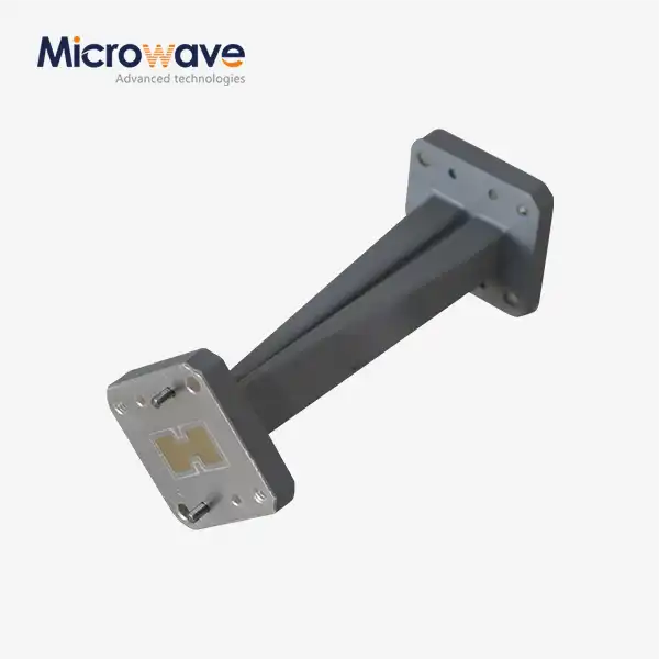
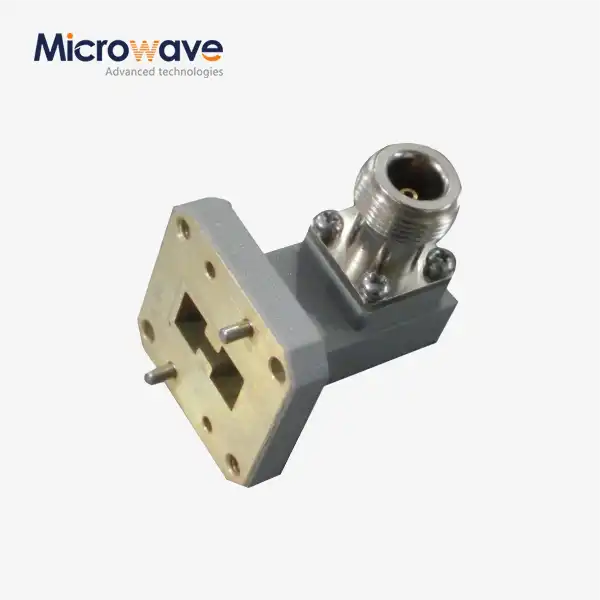
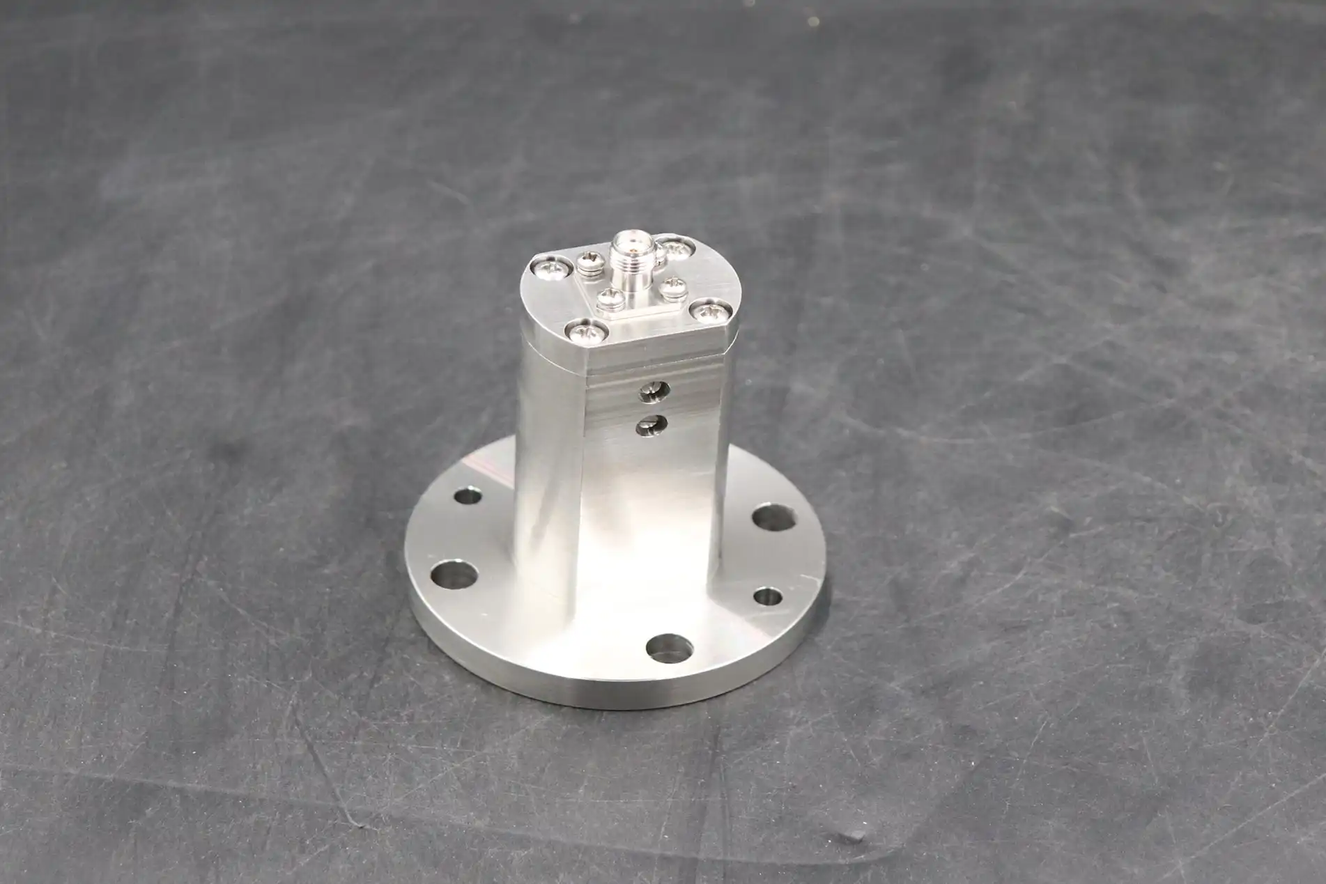
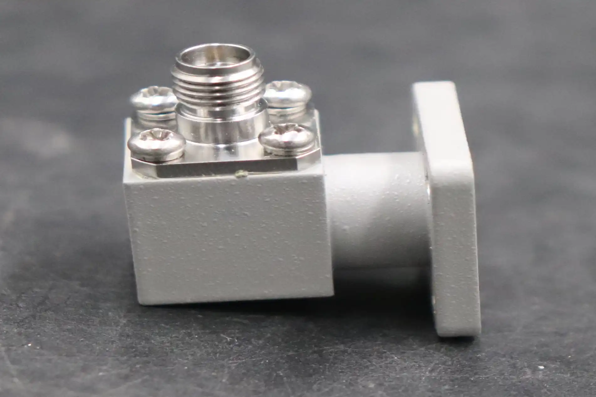
One of the most highly sensitive parts of any RF transmission chain is the waveguide-to-coaxial adapter that goes from a rectangular or circular waveguide to a coaxial line. Its job is to change the main TE10 waveguide mode into the TEM mode that can be used with coaxial cable. It has to do this with very little insertion loss, low VSWR, and stable phase response across the operating band.
In applications like military radar, 5G backhaul infrastructure, and satellite ground stations, these adapters handle forward power levels of hundreds to over a thousand watts. Small flaws become big problems at those levels. A scratch on the surface, a very small air gap at the flange interface, or a center probe that isn't lined up right can make the electric fields stronger than they should be, which can cause a corona discharge or a full arc breakdown.
Why High Power Magnifies Every Imperfection
The peak electric field inside a rectangular waveguide grows directly with the power that is sent through it. At 1 kW CW in a WR-90 waveguide, the field can go over 10 kV/cm, which is well below the arcing level if the surface finish, plating quality, or shape doesn't match what is expected.
Impedance mismatch at the coaxial interface creates standing waves that boost field peaks at fixed points along the transition. A VSWR of 1.5:1 can make the local field strength about 20% higher than what it was before.
Reflected power — if not absorbed or isolated — is reflected back into the waveguide-to-coaxial adapter joint, which increases stress there all the time.
Because of these changes, parts that work fine at 50 W might not work at all at 500 W. This isn't because of a flaw in the design, but because the margin of tolerance falls apart in the real world.
Diagnosing the Root Causes of Arcing: A Systematic Approach
To make a good diagnosis, you need to separate the electrical, mechanical, and environmental causes. For each category, there is a different way to inspect and fix the problem.
Electrical Breakdown: Fields, Mismatch, and Impedance Discontinuity
The most common type of electrical trigger is a change in impedance. Sometimes, the probe length, back-short distance, or dielectric support material inside the waveguide to coaxial adapter is off by as little as a few thousandths of an inch, which causes a localized impedance step. This makes the VSWR and return loss go up and focuses the E-field at the mismatch point. When the power is high, the focused field ionizes the air around it or breaks down insulating material, which starts an arc discharge.
Mechanical Failure Points
- Improper flange torque — Not tight enough leaves gaps between the waveguide flange and the flange, while too much torque deforms soft metal flanges and makes surface irregularities that act as field-enhancement sites.
- Misalignment between mating flanges — As little as a 0.1 mm lateral offset at a WR-42 flange can cause a current discontinuity that leads to resistive heating and eventually arcing.
- Connector wear or damage — When N-Type or SMA connectors are mated many times, the center pin contact gets weaker, causing variable contact resistance that gets worse when the temperature changes.
Environmental Stressors
When the relative humidity (RH) is above 85%, water can get into waveguide runs that are not under pressure. The local breakdown voltage drops by a large amount when water condenses on the adapter probe or the inner flange wall. Particulate pollution, like metal dust from nearby milling or cutting, builds electrical bridges across the adapter gap. Changes in temperature from -40 °C to +70 °C cause the aluminum bodies and copper metal layers to expand and contract at different rates. This creates tiny cracks in the surface finish that get bigger over time.
Proven Solutions and Best Practices to Prevent Arcing
The most important design choice is choosing the right waveguide-to-coaxial adapter material and shape. Here are the main technical and buying habits that really lower the risk of arcing.
- Specify silver or gold plating over OFHC copper or AL6061-T6 — Silver plating reduces skin-effect losses and keeps the surface smooth and free of oxides, which is important for high-field settings. Gold over nickel makes it less likely to rust, but it can cause passive intermodulation problems in receiver chains that are sensitive.
- Verify insertion loss and VSWR with calibrated VNA data — Any waveguide to coaxial adapter that will be used with a lot of power should come with swept VNA plots that cover the whole working band. If the insertion loss is more than 0.3 dB at the given frequency, the signal should be rejected before it is installed.
- Apply correct torque specifications per flange type — Standard UG-style flanges on WR-90 hardware usually need 5–8 in-lb. Always use a calibrated torque wrench and refer to the manufacturer's datasheet.
- Integrate a waveguide isolator upstream of the adapter — Put a high-power isolator between the source and the adapter junction to soak up reflected power before it can stress the transition. The High Power Waveguide Isolator from ADM has an average isolation loss of 20 dB and an insertion loss of 0.3 dB. It can handle up to 1000 W of forward power over an 800 MHz frequency and works reliably from –40 °C to +70 °C in aluminum or copper housings.
These techniques deal with the most common types of failure at the same time. In systems that send a lot of data and have changing load impedance, like phased array radars with beam steering or satellite uplink stations during handover events, an isolator in the feed chain is very helpful.
Real-World Case Studies: Overcoming Arcing in High-Power RF Systems
After increasing the broadcast power to 800 W, a regional satellite ground station that worked in Ku-band kept having arc events at the feed chain change. The original waveguide-to-coaxial adapter had silver covering that had corroded because it wasn't sealed well enough in a coastal humidity environment. Adding an upstream isolator and replacing the adapter with a hermetically sealed, re-silvered unit got rid of all arcing during a six-month monitoring period.
A defense contractor was putting an old S-band radar on a new vehicle platform. They kept running into VSWR spikes, which were caused by a waveguide-to-coaxial adapter that wasn't right for the non-standard waveguide flange and the standard N-Type coaxial port. The answer was a custom-machined connector with a probe length and back-short distance that were perfectly tuned and tested against MIL-DTL-45204 silver plating standards. After the installation, swept tests showed that the VSWR was less than 1.20:1 across the whole working band, and there were no arcing events during the 18 months that the system was in use.
One thing that both cases have in common is that arcing wasn't caused by a bad idea in general, but by a difference between what was needed for the system and what was in the catalog. Off-the-shelf parts couldn't fix the problem that custom-engineered solutions could, which were backed up by proper test data and material certification.
Conclusion
If you approach the problem in a methodical way, you can fix arcing in a high-power RF waveguide to coaxial adapter shift. The reasons for this problem can be found, measured, and fixed. They are field concentration, impedance mismatch, mechanical misalignment, and environmental damage. Precision-made adapters with the right plating, tested electrical performance, and the right safety features like in-line isolators give your system the extra room it needs to keep working without stopping. It is much cheaper to buy the right parts during the design phase than to find and fix arc damage on the job site.
FAQ
Why does arcing usually only appear at higher power levels?
When the power level drops below a certain point, the electric field inside the waveguide-to-coaxial adapter stays well below the ionization threshold of the medium around it. As the power goes up, so does the field, and any flaws in the shape or contamination that were there before become a starting place for the plasma discharge. At normal conditions, the breakdown voltage of air is about 3 kV/mm. At kilowatt-level CW operation, this gap can be reached faster than most engineers think.
How do I test for early arcing risk before full-power deployment?
It is possible to find impedance problems before power is applied by using a measured VNA to sweep across the whole working band. During bench testing, a low-power thermal scan with an infrared camera can also find resistive hotspots at flanges or connection surfaces that show bad contact or metal burrs.
What lead times and documentation should I expect from a reputable supplier?
Most of the time, ADM ships standard catalog units within a few business days. Custom-engineered adapters need to be reviewed by engineers, and prototypes need to be tested. Lead times are made clear during the quote process. There should be swept VNA test results, a Certificate of Conformance, and any necessary material certificates with every unit.
Partner With ADM for High-Power Waveguide Solutions
ADM designs radio transfers that work well in places with a lot of power. ADM is a reliable company that makes and supplies waveguide to coaxial adapters. They offer unique OEM configurations, ISO-certified manufacturing, and full test paperwork that includes VNA sweeps and material certifications. Our team is ready to help you with your project from the design stage all the way through delivery, whether you need a single prototype or a lot of them. You can email ADM at craig@admicrowave.com to see all of our products.
References
1. Pozar, D. M. — Microwave Engineering, 4th Edition. Wiley, 2011.
2. Collin, R. E. — Foundations for Microwave Engineering, 2nd Edition. IEEE Press / Wiley-Interscience, 2001.
3. Montgomery, C. G., Dicke, R. H., & Purcell, E. M. — Principles of Microwave Circuits. MIT Radiation Lab Series, Institution of Engineering and Technology, 1987.
4. IEEE Transactions on Microwave Theory and Techniques — Power Handling and Breakdown in Passive Microwave Components. IEEE, 2018.
5. MIL-DTL-45204D — Plating, Gold. U.S. Department of Defense Detail Specification, 2010.
6. IEC 61000-4-5 — Electromagnetic Compatibility (EMC): Testing and Measurement Techniques — Surge Immunity Test. International Electrotechnical Commission, 2014.