Pyramidal Horn Antenna Design: Gain and Bandwidth
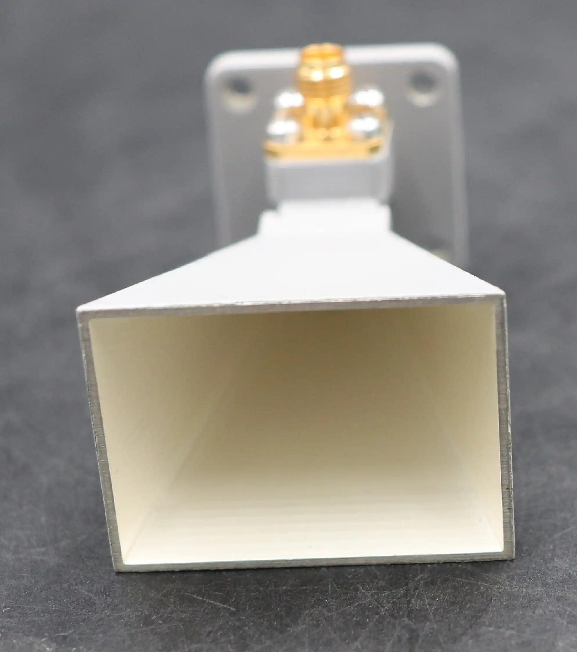
When we discuss pyramidal horn antenna design, we're talking about precision engineering that directly impacts signal transmission quality in mission-critical applications. The design fundamentally revolves around optimizing two essential parameters: gain and bandwidth. These antennas serve as impedance transformers, gradually transitioning from rectangular waveguide geometry to free space, ensuring minimal signal reflection and maximum power transfer. The pyramidal structure expands in both E-plane and H-plane dimensions, creating a controlled aperture that determines directivity, radiation pattern, and frequency response. Choosing the right design parameters means balancing aperture dimensions, flare angles, and horn length to meet specific performance thresholds required by aerospace, defense, and satellite communication systems.
Understanding Pyramidal Horn Antenna Design Principles
The main structure of pyramidal horn antennas depends on a few important parts that have a direct effect on how well they work. When procurement engineers and technical buyers understand these principles, they can figure out if something is right for their needs.
Aperture Geometry and Its Impact on Gain
Antenna gain is mostly determined by the size of the aperture. More electromagnetic energy is absorbed by larger openings, which makes the projected beam more focused and direct. The aperture sizes—width (a) and height (b)—must match the frequency range that is being used. An antenna made for X-band frequencies (8–12 GHz) usually has aperture sizes that are calculated to get the best phase distribution across the radiating surface. When the opening is too small compared to the wavelength, the gain is low, and when it's too big, the cost of making it goes up without any performance gain.
Flare Angle and Waveguide Transition
How easily the waveguide changes to the horn opening is controlled by the flare angle. The best flare angles reduce phase error at the aperture plane, which has a direct effect on the purity of the radiation pattern and the levels of side lobes. When the flare angle gets bigger, the antenna gets shorter, but the phase error gets worse, which lowers the gain and bends the beam. Gradual curve angles make the length longer, but they also give you more gain and better radiation patterns. When engineers define flare geometry, they have to weigh the need for performance against the amount of room available.
Material Selection and Surface Finishes
Pyramidal horn antennas are mostly made from copper or aluminum metals that have been carefully machined to very tight standards. Gold or silver plating on the surface can help keep skin effects from wearing off, especially at higher frequencies like Ka-band (26.5-40 GHz). Chemical passivation methods, such as Alodine covering, stop oxidation and keep the electrical qualities stable over a long period of time. The choice of material affects not only how well something works in terms of efficiency and noise, but also how long it will last in harsh environments like those found in radar systems, ground stations, and airborne platforms.
These design concepts are the basis for judging how well an antenna works. With this information, procurement workers can be more specific about technical needs and work with suppliers with trust, making sure that parts meet strict operational standards.
Calculating Pyramidal Horn Antenna Gain and Bandwidth
Engineers can guess how well a pyramidal horn antenna design will work before they buy it if they understand the math behind calculating gain and bandwidth.

Gain Calculation and Dimensional Parameters
The formula for figuring out antenna gain is G = 4π × A / λ², where A is the physical aperture area, and λ is the wavelength. This theoretical limit is based on the idea that the aperture is perfectly efficient. In practice, antennas only achieve 50–70% efficiency because of phase errors and edge diffraction. A horn in the X-band with a 10 cm x 8 cm opening that works at 10 GHz (λ = 3 cm) should have a theoretical gain of about 17.5 dBi. Getting the horn length and opening size to work together as well as possible reduces phase error and brings efficiency closer to the theoretical limit.
Bandwidth Considerations and Frequency Response
Bandwidth is the range of frequencies that the antenna works well with. It is usually measured by making sure that the VSWR stays below 1.5:1. Pyramidal horns naturally have broadband properties and can cover 40 to 50 percent of the fractional bandwidth. The bandwidth is determined by the cutoff frequency of the waveguide and the shape of the opening. For 8-12 GHz antennas to work, they need to connect to a rectangular waveguide (like WR-90) that has a cutoff frequency of about 6.5 GHz. Below this level, the receiver stops sending out radiation. Engineers find the right balance between aperture size and flare parameters to increase the bandwidth that can be used without lowering the stability of the gain across the entire operating range.
Simulation Tools and Design Validation
Engineers can simulate how horn antennas work with high-end electromagnetic software like CST Microwave Studio and Ansys HFSS before making a real prototype. These tools figure out cross-polarization isolation, gain versus frequency, and radiation patterns. Simulations find mistakes in designs early on, which lowers the costs of development and the risks of buying things. When buying custom antennas, buyers should ask for simulation results and measurement data from tests done in an anechoic room to make sure that the performance claims match the needs of the application.
Comparison of Pyramidal Horn Antennas with Other Horn Antenna Types
Figuring out the differences between horn geometries is important for expert buyers who need to match antenna types to working needs.
Pyramidal vs. Conical Horn Antennas
When rectangular waveguides change to pyramidal horns, linear polarization is kept naturally and effectively. On the other hand, conical horns flare out from circular waveguides, which means they can be used for circularly polarized tasks. When it comes to cross-polarization isolation, pyramidal designs usually go above and beyond 25 dB, which is very important for EMC testing and precise measurement tasks. When conical horns are added to standard rectangular waveguide systems, they need complicated rectangular-to-circular waveguide changes in order to work.
Sectoral and Broadband Horn Variants
Sectoral horns only flare in one direction, either the E-plane or the H-plane. They provide asymmetric beamwidths that are useful for some radar and scanning tasks. Broadband ridged horns have ridges inside them that lower the cutoff frequency. This makes the bandwidth extend to multiple octave ranges. However, ridged patterns make it harder to handle power and make it more complicated. When it comes to practicality, pyramidal horns are the best choice because they offer steady gain, reasonable bandwidth, and high power handling without any internal parts that are likely to break.
Cost-Efficiency and Application Fit
New materials, like lightweight composite structures and improved plating methods, improve efficiency while keeping prices low. Modular designs from top suppliers like L-com, ETS-Lindgren, and RF Elements have cut down on wait times and made integration easier. When procurement managers look at different types of horn antennas, they should think about the total cost of ownership, which includes the original price, the ability to customize, the shipping time, and the antenna's long-term dependability. Pyramidal horns are still the standard in the defense, aerospace, and telecommunications industries for uses that need high gain, linear polarization, and reliable performance.
Optimizing Pyramidal Horn Antenna Design for B2B Applications
Optimization methods change how well antennas work based on the situation they're in, which increases efficiency and lowers the cost of the whole system.
Gain Enhancement and Noise Reduction
To get the most gain in pyramidal horn antenna design, you need to make sure that the opening size is right for the wavelength and that phase error is kept to a minimum by carefully designing the flare. The signal-to-noise ratio gets better as more advanced surface finishes cut down on resistance losses. When weak signals from faraway spaceships reach satellite ground stations, even 1 dB of extra gain makes the link gaps and system reliability better. Cutting down on side and back bands, which can pick up unwanted overhead interference, is also an important part of noise reduction.
Frequency-Specific Design Adjustments
Geometries need to be customized for each frequency band. Because their wavelengths are longer, C-band antennas (4-8 GHz) have bigger openings and longer horns than Ku-band antennas (12-18 GHz). For millimeter-wave uses, like 5G backhaul at 28 GHz, manufacturing tolerances must be very tight, often within micrometers, to keep working properly. At ADM, our labs have measurement tools that can go up to 110 GHz. This lets us do exact testing across the entire microwave and millimeter-wave spectrum, making sure that designs meet strict requirements before they are sent out.

Customization and Procurement Logistics
A lot of the time, it's hard for procurement managers to balance technical needs with budget and time constraints. When you order a custom antenna, you have to tell them what frequency range, gain goals, polarization type, power handling, and mechanical link standards you need. OEM services are available from companies like ADM, which help with both fast development and full-scale production. Lead times range from two weeks for store models to eight weeks for patterns that are completely made to order. Ordering in bulk usually lowers unit costs, and building relationships with vendors guarantees priority support and faster response for tasks that need to be done right away.
Real-world case studies show that improvements can be measured. Working with ADM, a military contractor, made a Ka-band conical horn better for radar calibration. It now has 22 dBi gain and VSWR below 1.3:1 across 26-40 GHz. This ability made it possible to accurately find targets at long ranges, meeting strict MIL-STD compliance standards.
Purchasing Guide and Supplier Insights for Pyramidal Horn Antennas
To find the right antenna, you have to compare different providers based on their technical skills, quality certifications, and customer service after the sale.
Criteria for Evaluating Manufacturers
Technical buyers should look at a few key things when judging a maker. Quality and wait times are directly affected by production skills, such as the ability to do testing and machining in-house. Adhering to ANSI/CISPR testing protocols, ISO 9001 certification standards, and RoHS compliance shows that you care about quality management. Independent tests, done in measurement facilities like anechoic chambers and network analyzers, back up claims of performance.
Supplier Comparison and Product Benchmarks
Each of the top providers has its own unique benefits. L-com has a large catalog with many choices, and basic models ship quickly. ETS-Lindgren makes high-precision EMC testing devices that can be used to find calibration data. When it comes to antenna measurement bands, MI Technologies specializes in making unique solutions. ADM stands out because it has been making things for more than 20 years, has a 24-meter microwave lab that lets them measure far away at up to 110 GHz, and has a strong supply chain that lets them offer low prices without sacrificing quality. Our strict quality control and ISO 9001:2015 approval make sure that every antenna meets all of the requirements.
Pricing, Delivery, and After-Sales Support
Prices depend on the number of orders, the frequency range, and how complicated the customization is. Standard X-band horns cost between $500 and $2,000, but special millimeter-wave versions can cost more than $5,000. Delivery times depend on how much inventory is available and how much customization is needed. Support after the sale, such as professional help, installation instructions, and debugging, is very helpful because it cuts down on downtime and integration problems. Buyers can easily add antennas to complicated systems if the suppliers provide detailed instructions, modeling reports, and measurement data.
Conclusion
Pyramidal horn antenna design is still very useful in tough RF situations because they have a steady gain, works well across a wide frequency range, and can handle a lot of power. Procurement experts can make smart choices about where to buy things when they understand design principles, math methods, and optimization strategies. To make sure that the antennas you buy meet the needs of your project, you should compare different types of antennas, check out providers' technical skills and certifications, and use customization options. As microwave technology improves, working with seasoned companies like ADM gives you access to cutting-edge designs, thorough testing, and quick support, which ensures your business's long-term success.
FAQ
How does frequency influence pyramidal horn antenna design?
Physical dimensions are directly related to frequency. Higher frequencies mean shorter wavelengths, so the apertures and horns need to be smaller. An antenna for 10 GHz is bigger than an antenna for 40 GHz. The frequency band must also fit the connecting waveguide, and there must be cutoff frequencies below the working range to stop evanescent modes that stop radiation.
Can pyramidal horn antennas be customized for specific bandwidth demands?
Of course. Customization means changing the size of the opening, the flare angle, and the length of the horn to get the best performance across the frequency bands that you want. Engineers can make antennas with a narrow bandwidth for use with a single frequency or with a wideband setup that covers 40 to 50 percent of the bandwidth. Custom designs can also include specific goals for gain, polarization, and mechanical connections.
What factors should I consider when evaluating suppliers?
Quality of the materials, ability to measure, help with simulations, and ease of transportation are the most important things. Make sure that the companies you work with use precisely made conductive metals that have the right surface finishes. Make sure they have access to advanced modeling tools and anechoic chamber tests that they can do in-house. Following quality and environmental standards is shown by ISO certifications and RoHS compliance. Logistics that work, technical help that responds quickly, and customization options that are easy to use all make buying easier and lower project risks.
Partner with ADM for Precision Pyramidal Horn Antenna Design Solutions
Every project that Advanced Microwave Technologies Co., Ltd (ADM) works on is backed by its more than 20 years of experience making microwaves. Our ISO 9001:2015-certified facilities and 24-meter microwave darkroom allow for precise testing up to 110 GHz, which makes sure that your horn antennas perform at their best in terms of gain and bandwidth. Our technical team can help you with everything from fast prototyping to full-scale production, whether you need regular catalog models or ideas that are completely unique. As a reliable provider of pyramidal horn antenna design, we offer low prices, quick turnaround, and strict quality control that meets standards for defense, aircraft, and telecommunications. Get in touch with craig@admicrowave.com right away to talk about your needs, get a full price, and find out how ADM's superior engineering can make your RF systems better. Let's work together to make antenna systems that are effective and work well.
References
1. Balanis, Constantine A. Antenna Theory: Analysis and Design. 4th ed. Wiley, 2016.
2. Stutzman, Warren L., and Gary A. Thiele. Antenna Theory and Design. 3rd ed. Wiley, 2012.
3. Milligan, Thomas A. Modern Antenna Design. 2nd ed. Wiley-IEEE Press, 2005.
4. Silver, Samuel. Microwave Antenna Theory and Design. IET Electromagnetic Waves Series, 1984.
5. Kraus, John D., and Ronald J. Marhefka. Antennas: For All Applications. 3rd ed. McGraw-Hill, 2002.
6. IEEE Standard for Definitions of Terms for Antennas. IEEE Std 145-2013, Institute of Electrical and Electronics Engineers, 2014.