Planar Spiral Antenna Design: Key Principles and Best Practices
Designing effective spiral antenna systems requires balancing broadband performance with physical compactness while maintaining circular polarization purity. At Advanced Microwave Technologies Co., Ltd., our Planar Spiral Antenna solutions address the stringent demands of aerospace, defense, and satellite communication applications where ultra-wideband (UWB) coverage spanning 1 GHz to 40 GHz is essential. This guide explores the fundamental design principles, comparative advantages, procurement considerations, and integration best practices that enable engineers and purchasing managers to specify and deploy these frequency-independent apertures with confidence.
Understanding Planar Spiral Antennas: Fundamentals and Working Principles
When it comes to how they work, Planar Spiral Antennas are very different from regular resonant antennas. These structures don't use quarter-wavelength or half-wavelength resonances. Instead, they use a traveling-wave process where the active radiation area moves along the spiral arms as the frequency changes. This mapping of spatial frequencies lets a single opening keep its resistance and polarization properties the same over frequency ranges greater than 10:1.
Structural Geometry and Frequency Mapping
Geometry is usually based on Archimedean or equiangular (logarithmic) spiral equations. Archimedean spirals keep the distance between each turn the same, and equiangular shapes keep the angle of the growth rate the same. The lowest frequency is set by the outer width, where the radius is about one wavelength. On the other hand, the higher frequency limit is set by the inner feed area and terminal precision. Around 40 GHz, our designs at ADM use precise etching on low-loss substrates such as Rogers or Taconic laminates to make sure they work well.
Radiation Mechanisms and Polarization Properties
Circular polarization happens naturally when current flows along the spiral arms. At a certain frequency, a region becomes the main radiator when the diameter of that region is equal to about one wavelength. When energy moves away from the feed point, it radiates before it gets to the outer terminations. In many cases, this means that solid dampers are not needed. The rotational symmetry creates a circular polarization that can be right-hand or left-hand depending on the direction of the winding. The axial ratios are usually less than 3 dB across the operational band.
Impedance Characteristics and Matching Networks
In theory, self-complementary Planar Spiral Antenna designs have a free-space impedance that stays at 188 ohms. In real life, this balanced impedance needs to be changed to standard 50-ohm unbalanced transmission lines using integrated balun networks. We use infinite balun topologies and tapered microstrip baluns at ADM to keep the VSWR below 2:1 across the whole frequency range. This wideband matching feature gets rid of the need for frequency-selective tuning networks, making system integration easier while keeping signal loss to a minimum.
Simulation and Design Verification
Modern electromagnetic modeling tools, like HFSS, CST Microwave Studio, and FEKO, make it possible to accurately predict how an antenna will work before it is built. Through full-wave analysis, these platforms let engineers find the best arm width, spacing, substrate thickness, and cavity dimensions. We make sure that the goods we make fit the simulations within acceptable limits by measuring both near-field and far-field frequencies from 0.5 to 110 GHz in our 24-meter microwave darkroom. This mix of computer-aided design and real-world testing speeds up the development process and makes sure that custom OEM projects succeed on the first try.
Comparative Analysis: Planar Spiral Antenna vs. Other Antennas
Making good decisions about what to buy requires knowing when Planar Spiral Antennas are better than other types of antennas. Size, bandwidth, polarization, and gain are limited in different ways by different uses, which favor certain designs.

Bandwidth Considerations
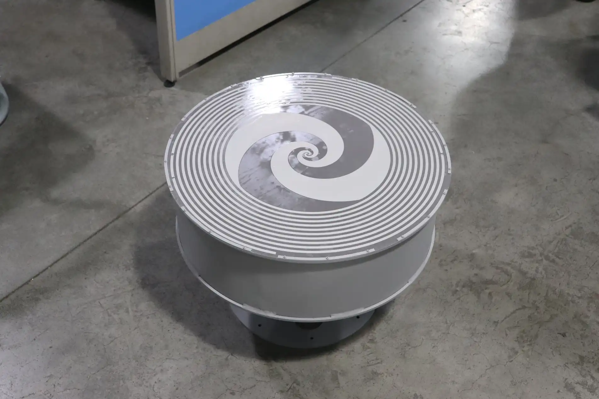
Like Planar Spiral Antennas, log-periodic antennas work at any frequency, but they need three-dimensional shapes with more depth. This bandwidth is squished down into a flat area by Planar Spiral Antenna shapes, which provide better volumetric efficiency in situations where profile height causes atmospheric drag or mechanical limitations. Planar Spiral Antennas cover more than eight octaves, while microstrip patch antennas only work well near their optimum frequency. They usually only offer a 5–10% fractional bandwidth.
Polarization and Pattern Stability
Helical antennas produce good circular polarization, but they need horizontal lengths of several wavelengths, which means they can't be used on small platforms. Our flat Planar Spiral Antennas get the same level of polarization clarity while being much thinner. When talking to satellite or radar systems that use circular polarization, dipole and inverted-F antennas lose at least 3 dB of signal. This is because they produce linear polarization. The Planar Spiral Antenna's circular polarization gets rid of orientation sensitivity, which is very important for mobile platforms that are toppling or changing their orientation quickly.
Gain and Directivity Tradeoffs
Horn antennas have better gain and directivity, but they take up a lot more space. A normal X-band horn could give you 15 to 20 dBi of gain, while Planar Spiral Antennas only give you 3 to 8 dBi. When hemispherical covering (70–90° beamwidth) is more important than pencil-beam directivity, on the other hand, the Planar Spiral Antenna's wider pattern is helpful. This wide field of view helps electronic warfare devices and radar warning systems find threats from different directions without the need for mechanical steering.
Manufacturing Complexity and Scalability
Fractal antenna designs say they are small because they use space-filling geometries, but they often have problems with having a narrow impedance bandwidth and being sensitive to fabrication. Conical spiral antennas are better than flat ones because they have a three-dimensional shape, but they are harder to put together. Standard PCB manufacturing processes are used for our planar designs, which let us make a lot of them at a low cost while keeping the tolerances very tight. Automatic optical inspection (AOI) tools check the trace width, spacing, and regularity of the substrate, making sure that the performance is the same from one production run to the next.
Best Practices in Planar Spiral Antenna Design for Industrial Applications
When turning theoretical ideas into strong hardware, you have to pay attention to things like the materials you use, the climate, and the facts of manufacturing, all of which have a direct effect on the long-term dependability of mission-critical systems.
Frequency Range Optimization
To set the working bandwidth, you must first choose the outer diameter for low-frequency coverage and the inner terminal dimensions for high-frequency response. A 150 mm outer diameter usually lets you work down to 2 GHz, and a feed point precision of less than 0.5 mm lets you go beyond 18 GHz. To find the best Planar Spiral Antenna dimensions, our customization process starts with the needs of the application. This could be for electronic support measures (ESM) across multiple threat radar frequencies or for satellite communication bands (C, X, and Ku).
Substrate Material Selection
Pattern alignment and efficiency are directly affected by the loss tangent and the consistency of the dielectric constant. The Rogers RO4003C and Taconic TLY-5 have been used in defense applications before and have stable electrical features from -55°C to +125°C with loss tangents below 0.002. The thickness of the substrate changes the impedance and bandwidth, so electromagnetic simulation is needed to make sure that the settings are just right. While thinner substrates lower the profile, they also increase conductor losses at lower frequencies. On the other hand, substrates that are too thick cause unwanted cavity resonances.
Cavity Backing and Unidirectional Radiation
Standard Planar Spiral Antennas send out waves in both directions. For uses that need patterns that only go in one direction, cavity backing filled with radar-absorbent material (RAM) is used. This method gets rid of back radiation, but it also loses about 3 dB of efficiency because it absorbs half of the power that is emitted. With careful phase matching, reflective metal holes can get this power back, but the frequency is limited. We help our clients decide if the increase in complexity and cost is worth it for their specific deployment scenarios based on the gain in improvement.
Environmental Protection and Radome Design
When water or ice builds up on Planar Spiral Antenna tracks that are out in the open, it changes the effective dielectric environment, which hurts pattern symmetry and axial ratio. Hydrophobic coatings or conformal potting compounds keep moisture out while having little effect on how well the electricity works. Thin radome layers made of low-loss materials like Rexolite or PTFE protect mechanically without adding a lot of insertion loss. Our designs are put through MIL-STD-810 environmental tests that include exposure to rain, ice, and salt fog to make sure they keep working well in real-world situations.
Customization for Large-Scale Procurement
Volume production introduces economies of scale, but strong quality control methods are needed. Our ISO 9001:2015 approval at ADM makes sure that the process is always controlled, from the sample to the finished product. Design for manufacturability (DFM) reviews find potential yield problems early on and change trace widths, clearances, and assembly procedures to make production as efficient as possible. Custom Planar Spiral Antenna lead times usually run from 4 to 6 weeks for prototypes to 8 to 12 weeks for production amounts greater than 100 units. Our global supply chain management makes sure that all of our orders arrive on time.
Procurement Guide: How to Source Planar Spiral Antennas Efficiently
A good buying process for a Planar Spiral Antenna combines technical performance needs with checking the supplier's skills, making sure the paperwork is correct, and thinking about the total cost of ownership, which goes beyond the initial unit price.
Supplier Evaluation Criteria
Reliability starts with being able to make things and meet quality standards. ISO 9001 shows that a process is mature, and AS9100 shows that a quality system is designed for aerospace. RoHS compliance ensures environmental responsibility, which is becoming more and more required by government procurement rules. In addition to certifications, you should also look at how much professional support the provider offers. For example, can they help with electromagnetic simulations, custom balun design, or system-level integration? At Advanced Microwave Technologies, our team has more than 20 years of experience with radio frequency (RF) technology. We help clients from the initial design phase through deployment and troubleshooting.
Documentation and Performance Verification
Instead of making general claims, comprehensive datasheets should list measured parameters. If you want to see real VSWR plots across the whole frequency range, not just average numbers, look for them. Radiation pattern cuts at different frequencies show that the pattern is stable, and axial ratio measurements show that the polarization is pure. Instead of just simulations, measurements of gain should be based on standard gain horn calibration. By asking for sample units, you can test them on your own system before placing a large order, which lowers the risk of integration problems.
Pricing Dynamics and Volume Considerations
Due to setup amortization and material buying benefits, unit pricing goes down a lot as the number increases. If you order 100 units, the price might go down by 30 to 40 percent compared to the price of the prototype. But secret costs like lead time delays, poor technical support, or quality slip-ups can wipe out any savings you made at first. When comparing suppliers, look at the total cost, which should include design iteration rounds, good documentation, and help after delivery. Our clear quoting process breaks down recurring and non-recurring engineering (NRE) costs so that you can plan your budget correctly.
Custom Design and Lead Time Management
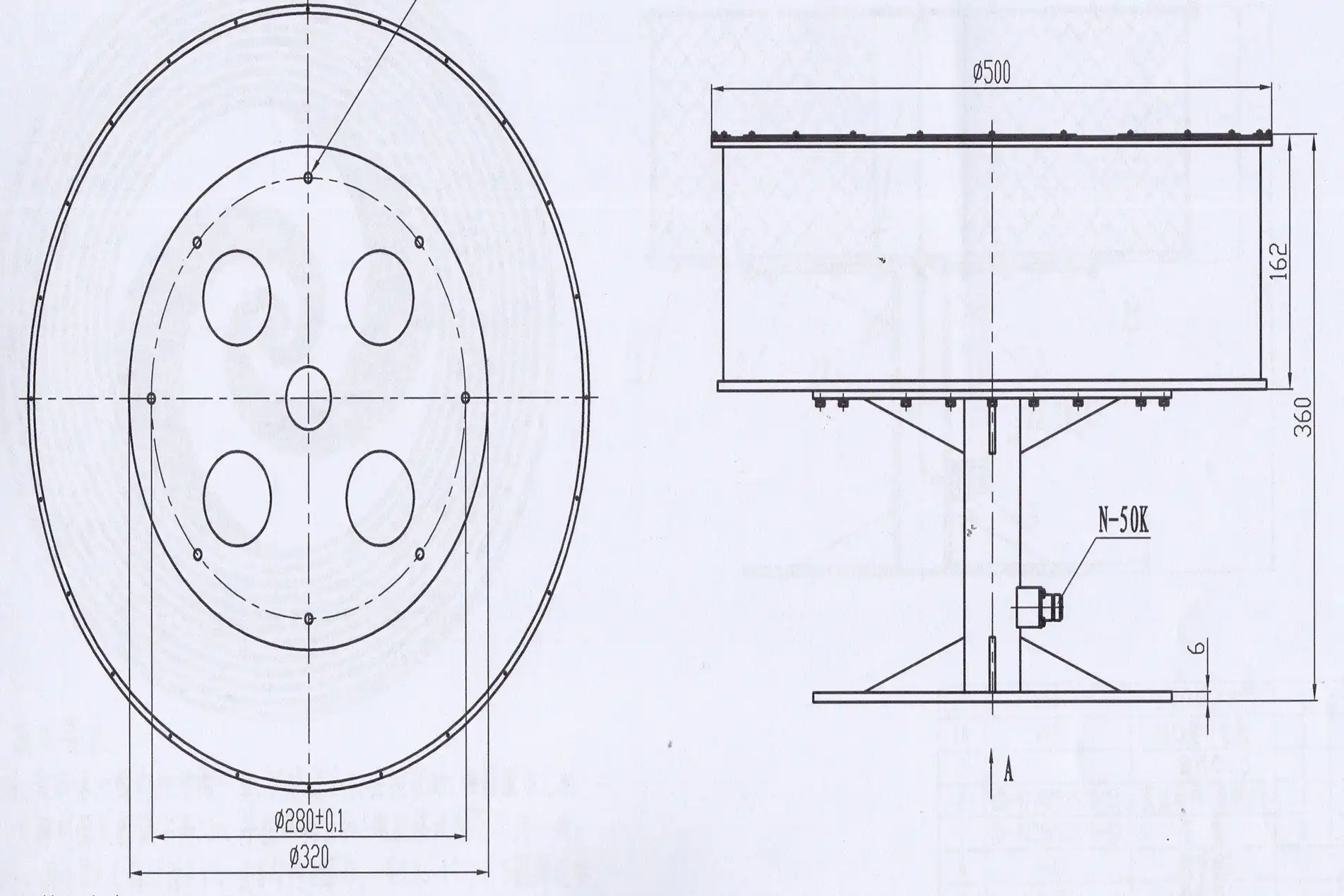
For custom antennas, you have to set electrical parameters like frequency range, VSWR, gain, and polarization. You also have to set mechanical parameters like size, weight, and mounting, as well as environmental parameters like temperature range, vibration, and humidity. The design cycle moves faster if the objectives are clearly stated at the start. We suggest staged development, which includes simulating the idea to make sure it works, building and testing a prototype, improving the design, and then putting it into production. This step-by-step method finds problems early, when fixing them costs less, so costly redesigns don't have to be done during mass production.
Optimizing Antenna Integration: Enhancing Performance and Reliability
To have a successful deployment, you need to think about more than just the Planar Spiral Antenna. You also need to think about things like impedance matching, installation effects, and long-term performance monitoring.
Impedance Matching and Feed Network Design
Even tho our antennas come with built-in baluns that are matched to 50 ohms, you may need to do more matching based on the length of your cables and the differences in the system's resistance. Time-domain reflectometry (TDR) finds impedance breaks in the radio frequency line, which helps find problematic connectors or wire connections. There are trade-offs between bandwidth and complexity when setting up matching networks at the antenna feed or system level. Measurements with a vector network analyzer show that the system's VSWR stays within acceptable limits across the operational band after it has been integrated.
Installation and Ground Plane Effects
Radiation patterns are changed by nearby structures and mounting surfaces that reflect and bend the radiation. Putting a Planar Spiral Antenna on a small ground plane makes the pattern less even and the back radiation stronger. According to our integration rules, the ground plane must be at least a certain size in relation to the wavelength at the lowest frequency. Computational electromagnetic modeling of the whole installation, including the antenna, mounting structure, and platform, predicts how well it will work in real life, which saves money on redesigns that need to be done after the fact. As part of our professional help for OEMs, we offer these simulation services.
Performance Troubleshooting Strategies
Some common problems are a drop in the axial ratio, which means there are problems with the feed network; VSWR spikes, which mean there are problems with the connectors or water getting in; and pattern distortion from installation effects. The first step in a systematic diagnosis is to take baseline measurements and compare current performance to data from an acceptance test. Visual and RF inspection of the connector can find mechanical damage. It is possible to make environmental rooms that simulate changing temperatures and humidity levels so that failures can happen again and again in controlled circumstances. Our expert team helps with online diagnosis and, if needed, on-site troubleshooting for integration problems that are more complicated.
Future Trends in Spiral Antenna Technology
New developments include Planar Spiral Antennas that can be reconfigured using RF switches or varactor diodes to change the frequency range on the fly. Metamaterial loading promises to reduce size while keeping bandwidth the same. Three-dimensional printing may make it possible to make complex cavity structures that aren't possible with traditional methods of production. Active embedded antennas with low-noise amplifiers or power amplifiers right at the antenna feed lower connection losses and improve system noise levels. As these technologies get better, we decide whether to add them to our product plan based on how reliable they have been in the past and what customers want. This way, we can be sure that innovations lead to real speed gains and not just lab experiments.
Conclusion
The Planar Spiral Antenna design strikes a balance between basic electromagnetic principles and real-world engineering limitations in order to provide ultra-wideband performance in small packages. Understanding the spatial frequency mapping, polarization mechanisms, and impedance characteristics helps you make smart choices about what to buy and how to specify it. By comparing Planar Spiral Antenna topologies to other types of antennas, it becomes clear when they are better for certain uses. Long-term dependability is ensured by using best practices for choosing materials, protecting the environment, and making sure that production can be scaled up. Effective buying looks at the skills of the seller, the quality of the paperwork, and the total costs of ownership that go beyond the original price. To successfully integrate a system, you need to pay attention to impedance matching, installation effects, and ways to fix problems. At Advanced Microwave Technologies Co., Ltd., we offer unique Planar Spiral Antenna solutions that meet the strict needs of the defense, military, and satellite communication markets. We do this by combining twenty years of manufacturing experience with cutting-edge measurement tools.
FAQ
What frequency ranges can planar spiral antennas practically cover?
The operating bandwidth of a Planar Spiral Antenna depends on the size of the device. The low-frequency limit is set by the outer width, which is usually one wavelength. The upper frequency is set by the inner feed precision and balun design. Our standard designs cover frequencies from 1 to 40 GHz. For custom applications, the range can be from 500 MHz to 110 GHz, based on the performance needs and size limitations.
How does circular polarization benefit satellite and radar applications?
When sending and receiving antennas use circular polarization, they no longer care about the direction of each other. When linear polarization is used, satellite links would lose a lot of signal because of Faraday spin through the stratosphere. Circular polarization helps radar systems tell the difference between signals that reflect directly and signals that travel more than one path. Quality Planar Spiral Antenna designs keep the axial ratio at 3 dB, which makes sure that there aren't too many polarization mismatch losses.
Can planar spirals handle high-power transmission applications?
These antennas are mostly used to receive signals or send signals with little power. The small trace widths near the center feed point and balun temperature limits make it hard to handle a lot of power. Power capabilities can be increased with special Planar Spiral Antenna designs that use wider wires, high-temperature substrates, and better cooling. However, other antenna types are often better for high-power microwave uses that need to transmit more than a few watts continuously.
Partner with ADM for Custom Planar Spiral Antenna Solutions
Advanced Microwave Technologies Co., Ltd. is ready to be your go-to Planar Spiral Antenna manufacturer. They offer precision-engineered solutions and have been in the RF business for over 20 years, so you can trust them. We can customize a wide range of things to meet your needs, including frequency range optimization, material choice, hole backing configurations, and environmental protection. Whether you need a prototype for R&D testing or a lot of them for integrating defense systems, our technical support and management of the global supply chain will make sure you get them on time and that the systems work together smoothly. Email our engineering team at craig@admicrowave.com to talk about the needs of your application, get full datasheets, or set up test units for samples. Find out how our 24-meter microwave darkroom testing center and full OEM services can help you get your next-generation radar or transmission system up and running faster.
References
1. Balanis, Constantine A. Antenna Theory: Analysis and Design, 4th Edition. John Wiley & Sons, 2016.
2. Corzine, Robert G., and Mosko, Joseph A. Four-Arm Spiral Antennas. Artech House Antennas and Propagation Library, 1990.
3. Volakis, John L. Antenna Engineering Handbook, 5th Edition. McGraw-Hill Education, 2019.
4. Stutzman, Warren L., and Thiele, Gary A. Antenna Theory and Design, 3rd Edition. John Wiley & Sons, 2012.
5. IEEE Standard 149-1979. IEEE Standard Test Procedures for Antennas. Institute of Electrical and Electronics Engineers, 1979 (Reaffirmed 2008).
6. Nakano, Hisamatsu et al. "Low-Profile Wideband Spiral Antenna with Cavity Backing." IEEE Transactions on Antennas and Propagation, Vol. 58, No. 9, September 2010, pp. 2742-2749.