


Miter Bend Waveguide in Microwave Systems: Features and Selection Tips
Engineers and procurement professionals often have to figure out how to send electromagnetic energy around tight corners without losing the integrity of the signal when they are working with Miter Bend Waveguide microwave systems that send high-frequency signals. This is exactly where waveguide parts that were carefully designed and built come in handy. The Miter Bend Waveguide stands out as a space-saving option that can redirect microwave signals at sharp angles, usually 90 degrees, while still having low insertion loss and great return loss. Traditional sweeping bends take up a lot of space. These small parts, on the other hand, use a precisely machined reflective plane set at a 45-degree angle to efficiently guide electromagnetic waves through changes in direction. Knowing the special qualities and choosing rules for these important RF parts can have a huge effect on how well a system works, especially in situations where space is limited and signal quality, reliability, and accuracy are all musts.
Understanding Miter Bend Waveguides
In our company, Advanced Microwave Technologies Co., Ltd., we have seen firsthand how Miter Bend Waveguides solve some of the most difficult problems in designing microwave systems. These unique parts are very different from regular curved bends because they use a different geometric approach to rerouting signals.
What Makes Miter Bends Unique
A Miter Bend Waveguide has a sharp corner shape and an internal reflective plane (the miter) that is perfectly positioned at a 45-degree angle. This reflective surface changes the impedance so that the reactive discontinuities that usually happen at waveguide structures' sharp corners are balanced out. When the electromagnetic wave hits this carefully designed surface, it reflects back in a way that lets it travel in a new direction with little energy loss. This design solves a major problem in RF engineering: how to change the direction of a signal in a small area without losing a lot of power through reflection or Voltage Standing Wave Ratio (VSWR). Traditional curved bends need a turning radius that is several times bigger than the waveguide width. This means that they can't be used in places where space is limited, like radar modules in the air or satellite payload assemblies.

Design Parameters That Drive Performance
The choice of material is very important for how well a waveguide bends. Our Miter Bend Waveguides are made with oxygen-free copper (OFC), which reduces conductor losses across the whole frequency range. Optional silver or gold plating lowers the surface resistance even more and protects against corrosion better. This is especially helpful for outdoor installations or marine settings where salt fog is a concern. Precision in geometry is very important. We use 5-axis CNC machining to make mitered cuts with ±0.01mm accuracy, which makes sure that the electromagnetic field is spread out evenly at the reflective junction. With this level of accuracy, there are no field concentration points that could cause high-power applications to fail. Integrated impedance matching features, like chamfers or compensating steps at the mitered joint, get rid of any remaining capacitive reactances. This makes the return loss performance better than 25dB across the whole operating bandwidth.
Where These Components Excel
Miter Bend Waveguides are very important for radar systems, both in the air and on the ground, because they make it possible to route signals more efficiently between transmitters, receivers, and antenna arrays. They are the best choice for defense contractors and aerospace system integrators because they keep signals intact while taking up 30–50% less space than curved alternatives. These parts help satellite communication ground stations send signals from feed horns to transceiver modules. The aerospace-grade versions we make can handle temperatures ranging from -45°C to +85°C, keep working even when they're vibrating a lot, and don't get damaged by radiation in space. In the same way, millimeter-wave 5G base stations benefit from having a small footprint, Miter Bend Waveguide, which lets engineers fit more parts into smaller and smaller enclosures without losing signal strength.
How to Choose the Right Miter Bend Waveguide for Your Microwave System
To choose the right waveguide component, you need to carefully look at the technical specs, the environment, and the supplier's skills. At ADM, we help our clients through this process to make sure they choose the best parts.
Defining Critical System Parameters
First, set the frequency band for operation. Our Miter Bend Waveguides can handle frequencies from 0.3GHz to 110GHz, which means they can be used for both old communication systems and new, cutting-edge millimeter-wave applications. WR-90 for X-band (8–12 GHz), WR-62 for Ku-band (12–18 GHz), and so on, must match the frequency range of your system. When parts don't match, they cause impedance discontinuities that slow down the system. Material choices and thermal management features are based on how much power the system needs to handle. Standard designs can handle power levels of up to 5kW in continuous wave (CW), which is enough for most radar and communication uses. To keep performance from dropping when temperatures get too high, custom designs may be needed for systems with more power that have built-in heat sinks or ceramic thermal interface materials. The size of something is important, especially in installations that are limited in space. Carefully measure the space you have, making sure to include not only the bend itself but also the hardware for mounting on the flange and any space needed for maintenance. Before you place an order, we can give you detailed mechanical drawings that show the exact sizes.
Evaluating Performance Metrics
Insertion loss is a measure of how much signal power is lost as an electromagnetic wave moves through a component. Our standard miter bends have an insertion loss of less than 0.1dB, which keeps the signal strength high so that the system can work at its full range and sensitivity. Return loss, which is how much energy is reflected back toward the source, should be higher than 25dB to keep upstream parts from getting messed up and to make sure that power transfer works well. When precise timing relationships need to be kept, like in phased array antennas or coherent radar systems, phase stability is very important. Electrical length can be changed by changes in dimensions caused by temperature. Our aerospace-grade parts are made with materials and designs that minimize phase shift across the operating temperature range.
Standard vs. Custom Solutions
Standard catalog components, which are cheaper and available right away, can be used for a lot of different tasks. It's necessary to use custom engineering when your system needs to work in unusual frequency bands, with non-standard flange types, or in harsh environmental conditions. ADM's OEM services include changing parameters like frequency range, bend angle, and power handling; adapting the interface to work with non-standard waveguide sizes or flange configurations; and improving performance for certain situations. Before we sell you something, we do an electromagnetic simulation to make sure that the custom design will work properly in your system architecture. This lowers the risk and keeps you from having to pay for expensive redesign cycles.
Supplier Evaluation Criteria
The quality of a component depends on the skills of the Miter Bend Waveguide people who make it and the quality systems they use. Look for suppliers that have ISO 9001 certification, which means they have strong quality management systems. RoHS compliance guarantees care for the environment and access to markets in areas with rules. For aerospace and defense uses, make sure the manufacturer has the right security clearances and can track the supply chain.ADM's labs have high-tech microwave measuring tools that can work up to 110 GHz. This lets them check the performance of every part thoroughly before sending it out. Our 24-meter microwave darkroom has the best facilities for testing antennas and parts. It can handle both near-field and far-field measurements across the 0.5–110 GHz frequency range. This infrastructure makes sure that the parts you get meet or go beyond the requirements in the datasheet.
Procurement Insights: Tips to Buy Miter Bend Waveguides Effectively
Getting the right parts doesn't just mean matching technical specs; it also means managing costs, making sure deliveries happen on time, and building relationships with vendors. These strategies help procurement managers get the best value for the project while lowering the risk. The prices of precision Miter Bend Waveguide components depend on a number of factors. Copper prices and plating options affect the cost of materials. For example, silver-plated parts are more expensive but have better conductivity and corrosion resistance. Tighter tolerances, higher frequencies (which need smaller dimensions and higher precision), and custom features all make manufacturing more difficult. Knowing about these cost drivers helps you negotiate better and make more accurate budgets. When planning a project, lead times should be given a lot of thought. Standard catalog items can usually be shipped in two weeks, but custom designs take six to ten weeks to make because they need time for engineering, making a prototype, testing it, and getting approval before they can be made. Tell them early on in the procurement process what your deadlines are, and if you want to be ready for any unexpected delays, you might want to keep a safety stock of important parts. Using sample evaluation programs is a good way to lower your risk. Ask for sample units to test in your real system environment before you commit to buying a lot of them. At ADM, we encourage this method because testing things in the real world builds confidence and often shows integration details that aren't clear from looking at the datasheets alone. When you commit to buying in bulk, you get lower prices per unit. But you have to weigh these savings against the costs of keeping inventory and the chance that specifications will change during long development cycles. After-sales service is what sets great suppliers apart from just-good ones. Technical advice can help you solve problems with integration and get the most out of your system. Custom manufacturing support lets you act quickly when changes to the design mean that parts need to be changed. Warranty protection against early failures and flaws in the way the product was made. At ADM, our expert engineering team helps with installation, performance testing, and ongoing technical support to make sure that everything works well and is reliable in the long term.

Performance Optimization and Maintaining Waveguide Efficiency
It's important to install and maintain even the best parts correctly so they work at their best throughout the lifecycle of the system. Signal integrity and reliability are maintained by knowing how common degradation mechanisms work and taking steps to stop them.
Understanding Loss Mechanisms
There are several things that can cause insertion loss in Miter Bend Waveguide components. When currents moving through the waveguide walls meet a certain amount of resistance, they lose energy as heat. Roughness on the surface, even tiny flaws, stops current flow and raises resistance. When there are breaks in the impedance, the energy Miter Bend Waveguide bounces backwards instead of sending it forward, which is called reflection loss. Behaviors that depend on frequency happen because as the frequency goes up, the skin's depth goes down, limiting current to a thinner layer on the surface, where resistance goes up. Mechanical assembly quality has a huge impact on the electrical performance. When flanges aren't lined up right, air gaps form between them. These gaps act as impedance discontinuities, lowering return loss and adding unwanted resonances. Over-torqued fasteners can bend flanges, and under-torqued connections allow movement, which causes electrical contact to happen and go off at times. By using calibrated torque wrenches and following the manufacturer's torque values, these problems can be avoided.
Installation Best Practices
Careful measuring and use of fixtures during assembly are the first steps in getting things lined up right. Waveguide runs need to be supported properly to keep them from sagging, which could put stress on the flange connections. Use vibration-dampening mounts and thread-locking compounds on fasteners to keep connections tight in places with a lot of vibration, like airplanes or mobile radar installations. Protecting the environment makes parts last longer. Even though our industrial-grade parts have IP65 sealing and corrosion-resistant plating, they need extra protection in harsh outdoor environments. This can be provided by weatherproof enclosures or environmental conditioning. When used in marine settings, our anti-salt sprays offer better defense against the damaging effects of saltwater vapor.
Preventive Maintenance and Troubleshooting
Problems are found before they cause the system to fail through routine inspection. During regular maintenance times, look at the flange connections visually for corrosion, physical damage, or fasteners that are coming loose. Use time-domain reflectometry (TDR) or vector network analyzer (VNA) measurements to baseline component performance, then repeat periodically to detect degradation trends. One common way things fail is for the flange gasket to compress over time, which raises the contact resistance and lowers the return loss. Thermal cycling can wear down solder joints on parts that have been plated. Moisture getting into outdoor installations that aren't properly sealed leads to oxidation on metal surfaces. Finding these problems early lets you fix them before they become completely broken. Partnering with experienced suppliers provides access to ongoing support and management of the lifecycle of a component. At ADM, we help customers figure out why their systems aren't working right, suggest design changes based on our knowledge from the field, and provide replacement parts that are exactly the same as the ones that came with the original equipment. This long-term partnership approach keeps the system working well for as long as it is used.
Conclusion
To choose the right waveguide components, you have to think about technical performance, physical limitations, and cost. Miter Bend Waveguide solutions are very useful in situations where space is limited and traditional curved bends won't work. They can redirect signals with little loss and great return loss properties. Knowing the pros and cons of miter bends compared to other routing options like curved bends, flexible waveguides, and different plane orientations helps engineers and procurement professionals make smart choices that meet the needs of the application. A successful procurement process includes more than just choosing the right parts. It also includes evaluating the supplier, making sure the system is installed correctly, and keeping it running smoothly throughout its lifetime. Organizations can make their microwave systems more reliable and efficient by working with experienced manufacturers who offer technical support, the ability to customize systems, and full-service support.
FAQ
1. What frequency ranges do miter bend waveguides typically support?
Miter Bend Waveguide products work across a huge range of frequencies, from 0.3GHz at the low end to 110GHz at the millimeter wave end. The frequency range depends on the size of the waveguide. Waveguides with larger rectangular cross-sections, like the WR-2300, can handle lower frequencies (0.3–0.5 GHz), while waveguides with smaller cross-sections, like the WR-10, can handle higher frequencies (75–110 GHz). The WR-90 and WR-62 waveguide sizes cover the X-band (8-12 GHz) and Ku-band (12-18 GHz) frequency ranges, which are commonly used for satellite communication and radar applications.
2. Can miter-bend waveguides be customized for specific project requirements?
ADM's main skill is customization. We can change frequency ranges, bend angles (beyond the standard 45-degree configuration), and power handling specs to fit different application needs. Customizing the interface lets you use waveguides of non-standard sizes or flanges of specific types, and optimizing the dimensions lets you fit them into smaller devices. For tough jobs, performance factors like insertion loss, temperature stability, and environmental sealing can be improved. Our technical team works with customers all the way through the design process and uses electromagnetic simulation to make sure the design works before it is built.
3. How do 45-degree miter bends minimize signal losses compared to curved bends?
The 45-degree miter shape effectively reflects electromagnetic waves through a flat surface that has been precisely machined and acts as an impedance transformer. By canceling out capacitive and inductive reactances, this surface makes up for the reactive discontinuities that come with sharp corners. When designed correctly with compensating features like chamfers or matching steps, the miter bend has insertion loss below 0.1dB and return loss above 25dB. This is the same level of performance as curved bends, but in a package that is 30–50% smaller. Tolerance requirements of ±0.01mm make sure that the field is spread out evenly and that reflections are kept to a minimum at the mitered junction.
Partner with ADM for Premium Miter Bend Waveguide Solutions
Advanced Microwave Technologies Co., Ltd has been making microwave parts for more than 20 years and can help you with your most difficult RF projects. Our carefully designed Miter Bend Waveguide assemblies are used in mission-critical systems in the defense, aerospace, satellite communication, and industrial fields that can't afford to lose reliability. As a top manufacturer of miter bend waveguides, we use ISO 9001-certified quality systems along with cutting-edge measurement tools, such as our ultra-modern 24-meter microwave darkroom, to check performance at frequencies as high as 110 GHz. Our engineering team can help you with both standard catalog parts that can be put together quickly and fully customized designs that are made to fit your exact needs. They also offer full technical support for all of their work. Get in touch with craig@admicrowave.com right away to talk about your project needs, get performance data, or set up a sample evaluation. Let us show you how ADM's waveguide technologies can make your system work better while still meeting the high standards your applications need.
References
1. Marcuvitz, Nathan. Waveguide Handbook. Institution of Engineering and Technology, 1986.
2. Pozar, David M. Microwave Engineering, 4th Edition. John Wiley & Sons, 2011.
3. Collin, Robert E. Foundations for Microwave Engineering, 2nd Edition. IEEE Press, 2001.
4. Montgomery, C.G., Dicke, R.H., and Purcell, E.M. Principles of Microwave Circuits. McGraw-Hill, 1948.
5. Saad, Theodore S. Microwave Engineers' Handbook, Volume 1. Artech House, 1971.
6. Harvey, A.F. Microwave Engineering. Academic Press, 1963.
YOU MAY LIKE
 VIEW MORELog Periodic Antenna
 VIEW MOREConical Circular Polarization Horn Antenna
 VIEW MORELadder Membrane Square Dual Circular Polarization Horn Antenna
 VIEW MOREDual Linear Broadband Circular Polarization Horn Antenna
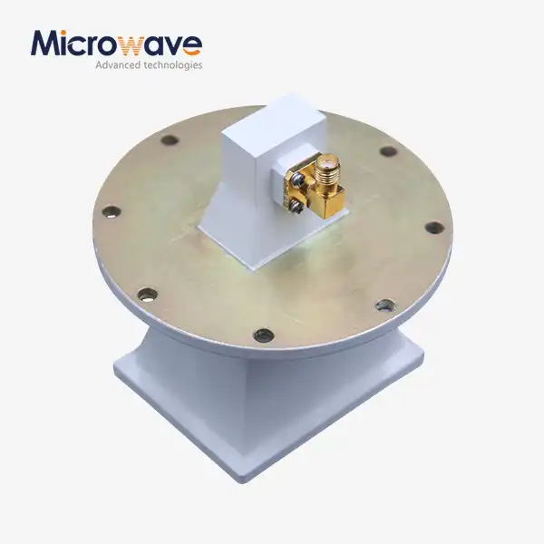 VIEW MOREPyramidal Linear Polarization Horn Antenna
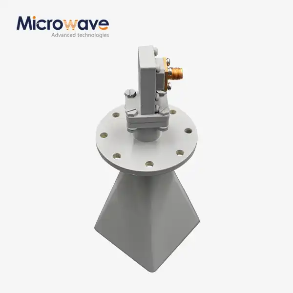 VIEW MORELow Side Lobe Diagonal Linear Polarization Horn Antenna
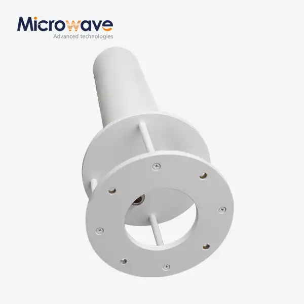 VIEW MOREQuadrifilar Helix Antenna
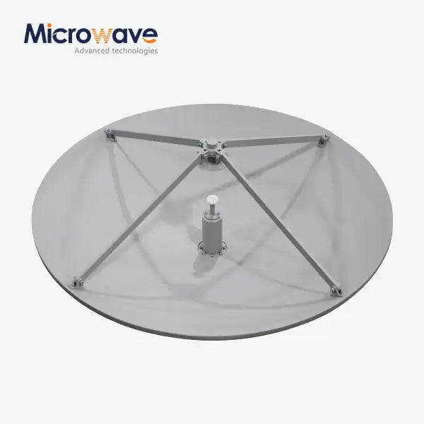 VIEW MORECassegrain Antenna
