




Low loss bandpass filters for 5G, Radar, and Satellite Systems
Low loss bandpass filters exclude undesired signals outside that band while allowing a specified band to pass with little power loss. Five-G networks, radar, and satellite systems use reduced insertion loss to protect receivers, link budgets, and heat. Waveguide, cavity, and coaxial designs have the least loss due to high-Q resonators. Ceramic, SAW, and BAW filters lose size due to shrinkage. Engineering, OEM, system integrator, distributor, and procurement teams may easily evaluate vendors, technologies, and standards using this reference. Everything following utilises basic language and validated technical facts.
What Are Low Loss Bandpass Filters and How Do They Work?
Passband, Stopband, and Insertion Loss Explained
It has three parts: a passband, two stopbands, and a center frequency. It lets through a certain range of frequencies, which is called the passband. Above and below it are the stopbands, which are places where the filter blocks signals by reflecting or absorbing them. Engineers use decibels to show how much power the filter takes away inside the passband. This is called insertion loss. Power is cut in half by 3 dB, and only 79% of the power is left after 1 dB. That is not the same thing as having a wide passband, high Q, high rejection, or high selectivity. Each of those traits is its own thing, and they should all be listed on a datasheet.
How Resonators and Coupling Create Selectivity
All bandpass filters employ resonators to store energy at a certain frequency. Resonators are chained via coupling structures. Signals near the center frequency charge the resonators and travel from input to output. Since signals beyond the passband can't activate the chain, the filter reflects or weakens them. Resonators steepen skirts but increase insertion loss, so designers must balance loss and rejection budgets. High-Q resonators store energy efficiently when unloaded. Coaxial cavity designs may have unloaded Q values of 500 to over 5,000, depending on housing size. So they lose little at microwave frequencies.
Why Low Insertion Loss Matters
When choosing low loss bandpass filters, note that loss before the first amplifier quickly increases system noise. A filter with 1 dB loss reduces receiver sensitivity by 1 dB. Send-side power loss generates heat outside the filter. Heat may affect frequency, stress connections, and require extra cooling in open-air cabinets or racks. Thus, reduced loss preserves satellite uplink connection margins, radar detection ranges, and 5G radio coverage. Buyers often compare insertion loss initially. Rejection, power, and size also influence the ideal decision.
Insertion Loss Sources and Filter Technologies: Cavity, Ceramic, SAW, and BAW
What Drives Insertion Loss
RF currents form a thin coating on the conductor. A rough surface or faulty plating immediately increases resistance since the copper layer is just 0.66 micrometres thick at 10 GHz. Silver plates high-quality coaxial filter housings and resonators because it conducts electricity best. Dielectric materials produce loss; therefore, air-filled cavities and waveguides lose less than ceramics. Incorrect connection impedance and coupling waste energy and increase VSWR. Losses increase with pollution and tuning errors. Environment matters too. Center frequency fluctuates with temperature. Invar tuning rods or temperature-compensated devices may maintain drift below 5 ppm per degree Celsius in coaxial setups. Vibration, moisture, and oxidation might affect results; therefore, request calibrated test data across all power and temperature ranges.
Cavity, Coaxial, and Waveguide Filters
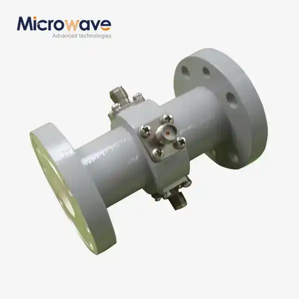
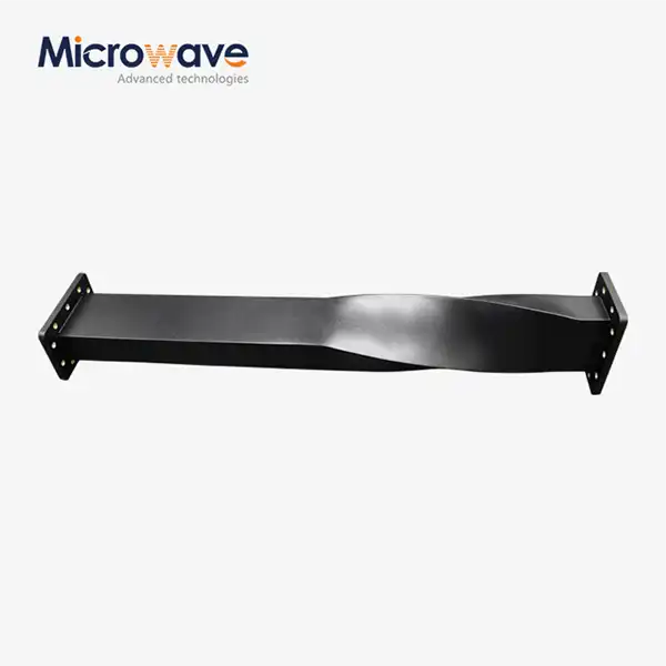
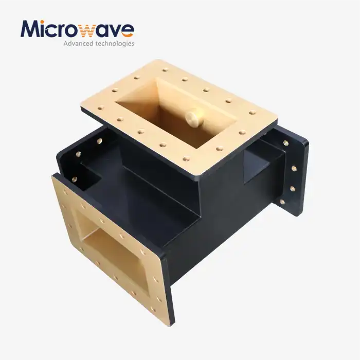
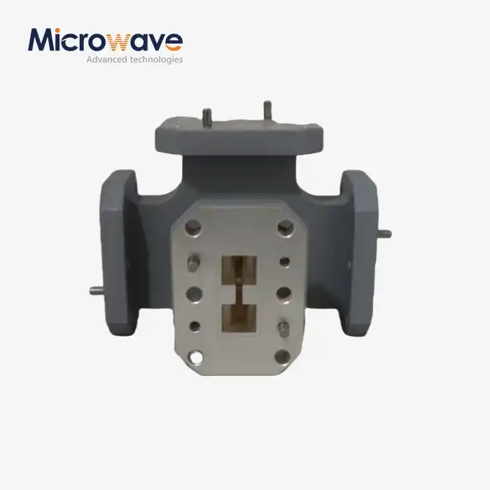
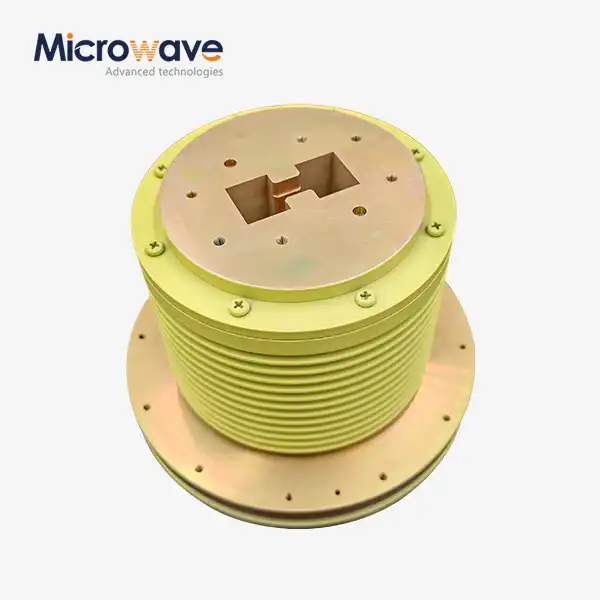
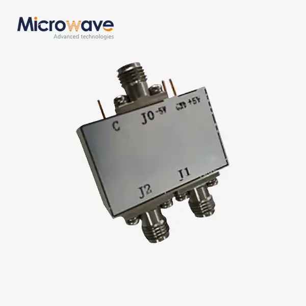
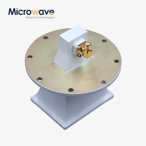
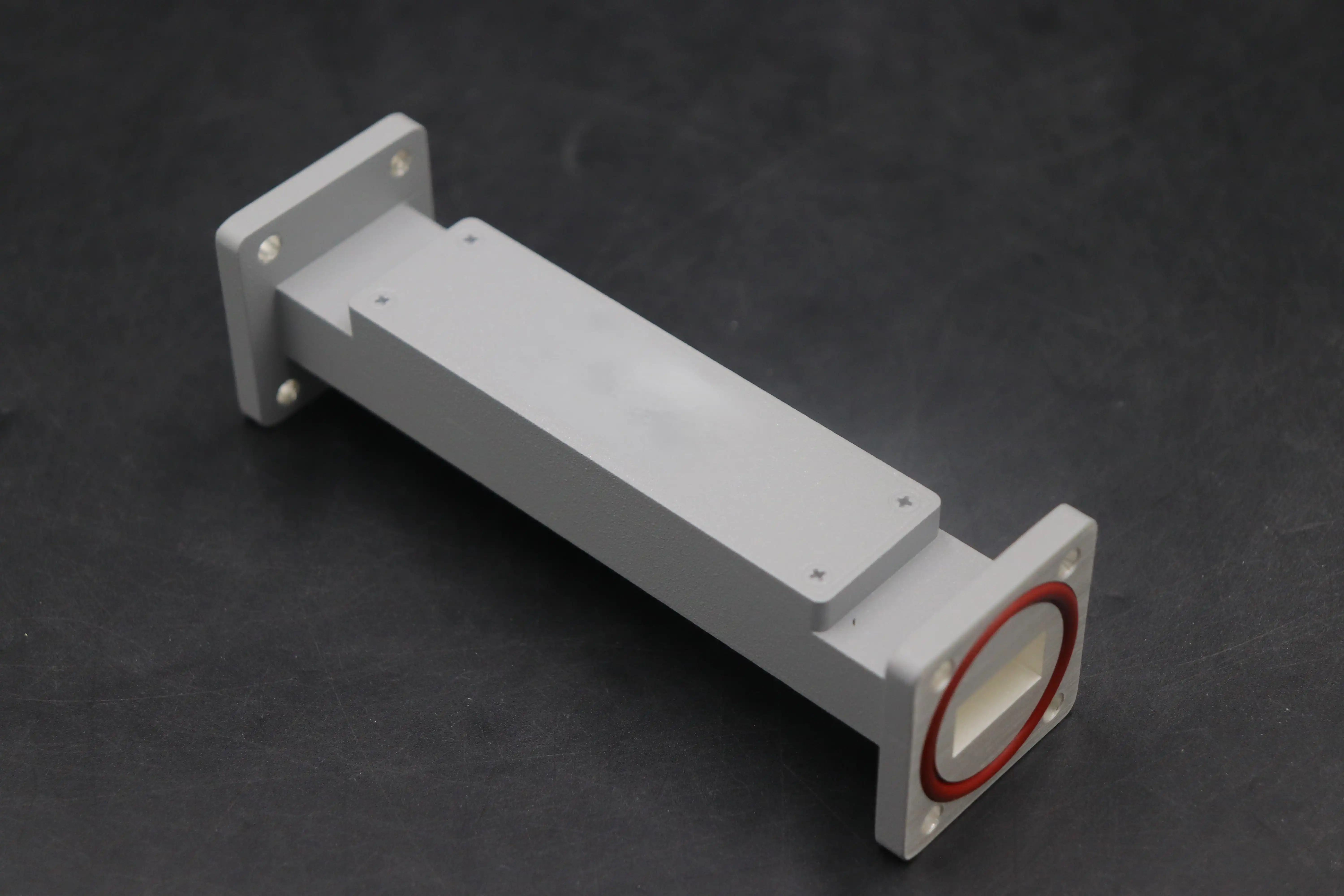
Cavity filters demand more room and mechanical adjustment but have low insertion loss, high Q, great selectivity, and high power handling. Cavities like coaxial bandpass filters are common. A matched 50-ohm passband often has VSWR better than 1.25:1. Without a load, the core resonator rod in a conductive enclosure has a Q range of 500 to over 5,000. Coaxial designs have greater Q than ceramic filters and are smaller than waveguide filters below 10 GHz. Hollow metal chambers linked by irises or posts form a waveguide bandpass filter. Because air fills the structure, it operates from 1 GHz to 100 GHz and higher, handles kilowatts to megawatts, and has minimal loss.
Ceramic, SAW, BAW, and Planar Filters
Ceramic filters employ dielectric resonators to minimise size and maintain performance. This makes them popular in mobile phones and other small devices. Much more is lost than in air traps. SAW and BAW filters share tiny footprints, excellent frequency control, and high-volume manufacture. SAW filters are excellent at lower frequencies and BAW filters at higher frequencies. Know its power capacity before buying either. The microstrip and suspended-substrate planar filters are easier to install on circuit boards and use less power. For dielectric loss reduction, suspended-substrate circuits are in the air. Choose wisely according on frequency, size, power, and loss budget.
Low Loss Bandpass Filters for 5G, Radar, and Satellite Systems
5G Base Stations and Small Cells
The 3GPP states that 5G networks employ FR1 bands up to 7.125 GHz and FR2 millimeter-wave frequencies from 24.25 to 52.6 GHz. For radio units, base stations, small cells, and distributed antenna systems, filters must separate adjacent channels, suppress harmonics, and prevent site interference. The transmit and receive bands of duplexers are separated by coaxial filters to protect the receiver from transmitter noise. Thermal stability and minimal packing are necessary for outdoor cabinets due to temperature swings. Low passive intermodulation (PIM) design prevents false signals from entering the receive band and boosting the noise floor with the correct quantity of non-magnetic materials and connection torque.
Radar Platforms
For radar receivers to be able to find things, they need low loss before the low-noise amplifier. They also need to have good peak and pulse power performance, high rejection, and controlled group delay. Coaxial bandpass filters are low loss bandpass filters; they get rid of unwanted harmonic emissions and protect the amplifier from strong jamming signals. Their rigidity makes them suitable for use in both air and ship vibrations. When it comes to IEEE letter designations, X-band radar works between 8 and 12 GHz, and waveguide filters are the best way to get high power with low loss. During a pulse, peak power can be much higher than average power, so engineers should look at both ratings as well as how much heat is being lost.
Satellite, Aerospace, and RF Test Systems
Satellite ground stations and payloads make it important that they are light, can work in a variety of environments, can be tracked, and last a long time. Geostationary orbit is about 35,786 km above the equator. Downlink filters protect weak signals that travel from space. Uplink filters need to let a lot of transmit power through with little loss. Electronics used in space also have to deal with vibration, changing temperatures, and strict rules about documentation. Low-loss filters are also helpful for RF test systems because they add more signal margin, which makes measurements more accurate. Microwave measuring tools up to 110 GHz are used in ADM's labs, and our products are ISO 9001 certified and RoHS compliant for use in defense, aerospace, satellite communications, and navigation.
Key Specifications and Selection Guide for Low Loss Bandpass Filters
Electrical Specifications to Request
Along with the center frequency, passband limits, frequency tolerance, insertion loss, return loss (VSWR), rejection at named offset frequencies, group delay, phase response, and impedance (usually 50 ohms), an electrical specification will also list the following. Not just the middle of the passband, but also the edges, because loss tends to rise as you move toward the edges. Also, list the conditions for measuring, such as the temperature, the way the measurement will be done, the type of connector, and the frequency step. For the same design, two suppliers can give different loss values if they measure it in different ways. A lot of coaxial designs try to keep the insertion loss below 1 dB, and a low return loss means that the power is being transferred well.
Power and Mechanical Requirements
Average, peak, pulse, and continuous wave are the different types of power ratings. A 5G transmitter path is more interested in average power than peak and pulse ratings for radar. The rating will only work in a real cabinet if the thermal dissipation and operating temperature are right. Connectors, housing material, mounting, sealing, size, weight, and surface treatment are some of the mechanical details. Housings made of aluminum or brass that are plated with silver stop skin-effect losses, and plating that is trivalent chromium stops oxidation. Even if the electrical goal is met, but the filter doesn't fit the enclosure, the project is still a failure. I think you should include all of these things in the first request.
Technology Comparison and Decision Table
The following table uses the above-mentioned properties to match common technologies to system needs.
| Technology | Loss | Size | Power | Typical fit |
|---|---|---|---|---|
| Waveguide | Very low | Largest | Highest | Radar, satellite, millimeter-wave |
| Coaxial cavity | Low | Medium | High | 5G base stations, radar, RF test |
| Ceramic | Moderate | Small | Moderate | Compact 5G radios |
| SAW/BAW | Higher | Smallest | Low | Compact wireless devices |
High Q is a design parameter, not a general way to rate quality. Narrowband designs are more selective but tend to show more loss for a given Q. Wideband designs, on the other hand, cover more channels but are less selective. It may be cheaper per unit to buy a standard bandpass filter, but a low-loss design can cut down on the need for amplifier gain, cooling, and testing again. Don't just compare unit prices; compare how the whole system works when selecting low loss bandpass filters.
How to Choose, Buy, and Customize Low Loss Bandpass Filters
A Practical Procurement Process
I think a simple order is best. To begin, you need to choose a frequency, passband width, loss target, rejection, matching, power, temperature, and environment. Next, make sure that your priorities are in line with the use case: small consistency for 5G, pulse handling for radar, or qualification and long-term supply for satellite systems. Then, look at how well the suppliers can help with design, prototyping, RF testing, documentation, customization, and production control. The last step is to make sure that the samples work properly electrically, mechanically, in the environment, and that they are representative of the whole production run. It's important to include mechanical drawings, connectors, quantity, annual demand, target price, delivery date, packaging, country of origin, certifications, inspection documents, warranty, and needs after the sale in a strong RFQ.
Common Procurement Risks
If you only look at the price per unit, it can make the costs of amplifier gain, cooling, retesting, qualification, and field service go up. You should only compare data from different suppliers if the temperature, power, connectors, measurement span, frequency points, and calibration are all the same. Check the manufacturing tolerances, lead times for prototypes and large orders, minimum order quantities, supply continuity, and safety stock choices. Carefully check the shape and mechanics of the connectors, as even a small difference can lead to damage or reflections. Don't approve a standard replacement filter until it has been tested for electrical, thermal, and mechanical issues. These checks don't take long, but they keep delays and extra costs from happening later. It's much cheaper to do a quick review before the purchase than to start over after the delivery.
Custom Design and Manufacturing Process
The first step in a custom project is to look over the requirements to see if there are any problems with things like low loss, high rejection, small size, passband width, power, cost, and delivery time. Even though electromagnetic simulation helps improve things like resonator size, coupling, filter order, housing shape, and connector transitions, real prototypes are still needed. Following this are the steps of reviewing the design, making it, measuring the RF signal, checking the mechanics, tuning it, and getting customer approval. Production quality control checks the materials, sizes, plating, assembly, RF testing, paperwork, and the ability to track each batch against the acceptance criteria that were agreed upon. ADM was founded in the 2000s and has more than 20 years of experience working with microwaves. They offer OEM services, quick prototype turnaround, technical support, and exporting to over 110 GHz around the world.
Conclusion
In order to protect receiver sensitivity, link budget, and thermal performance in 5G, radar, and satellite systems, low loss bandpass filters pass the desired band with little power loss. Insertion loss is caused by things like conductor resistance, surface finish, dielectric material, mismatch, and changes in the environment. This means that testing, materials, and plating are important. Cavity, coaxial, and waveguide designs have the least amount of loss and can hold the most power. Ceramic, SAW, BAW, and planar designs, on the other hand, are smaller. For example, for 5G, rejection and pulse power are important, as well as channel isolation and compactness. For radar, low mass, qualification, and traceability are important. Values on a datasheet need to be confirmed by repeated measurements and sample validation. It's not enough to just look at one number; the best choice takes into account power, stability, size, environment, long-term supply, and loss with rejection.
FAQ
Q1: What insertion loss counts as low?
There is no single definition. Loss that is acceptable depends on the technology, power, frequency, passband width, and use. A lot of coaxial designs try to get below 1 dB, but a narrow filter for millimeter-wave frequencies might need a different goal. It is important to always compare values at the same temperature and frequency points.
Q2: How do cavity and ceramic filters differ?
Cavity filters can handle more power and have a higher Q, but they take up more space and need to be tuned mechanically. Ceramic filters are small and stable, making them perfect for equipment that doesn't have a lot of room. The size of coaxial cavity designs is in the middle of ceramic and waveguide.
Q3: Which characteristics matter most in radar?
The most important things are low loss, high rejection, controlled group delay, and the right peak and pulse power ratings. Pulse power is important to pay attention to because peak levels can be much higher than average levels.
Q4: Can filters be customized, and what should I send?
Yes. This section talks about the center frequency, passband width, insertion-loss target, rejection, power, interfaces, quantity, and environmental needs. Drawings and a planned delivery date are also useful. These specifics can be reviewed by ADM engineers working on 5G, radar, or satellite projects.
Request a Low Loss Bandpass Filter Quote from ADM
Tell ADM about your frequency range, insertion loss goal, rejection, power rating, connectors, quantity, and delivery schedule. ADM has been making low loss bandpass filters for microwaves for more than 20 years and offers prototyping, technical support, quick turnaround, strict quality control, and exporting all over the world. To get a technical review or quote for your 5G, radar, or satellite project, email craig@admicrowave.com.
References
1. Microwave Engineering, 4th Edition (Wiley), 2012
2. Microwave Filters for Communication Systems, 2nd Edition (Wiley), 2018
3. Radar Handbook, 3rd Edition (McGraw-Hill), 2008
4. Satellite Communications Systems, 5th Edition (Wiley), 2009
5. IEEE Std 521, Standard Letter Designations for Radar-Frequency Bands (IEEE), 2019
6. 3GPP TS 38.104, NR Base Station Radio Transmission and Reception (3GPP), 2020