




3 dB to 40 dB: Picking Attenuation Values in Waveguide Fixed Attenuators
To find the right value for a waveguide fixed attenuator, take the power your source sends and subtract the amount of power that the next part can safely handle. Then, add a small amount. To level balance and calibrate, use 3 to 10 dB. To test the transmitter, use 20 dB. For strong reduction and receiver protection, use 30 to 40 dB. Then make sure the unit fits your WR size, works with your frequency range, and can handle both your average and peak power. That choice should be easy for engineers and buyers after reading this guide.
Why the Attenuation Value Matters in a Waveguide System
What a Waveguide Fixed Attenuator Does
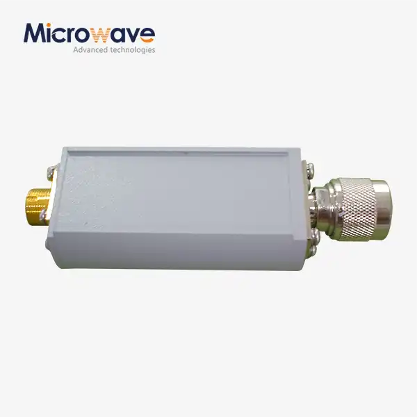
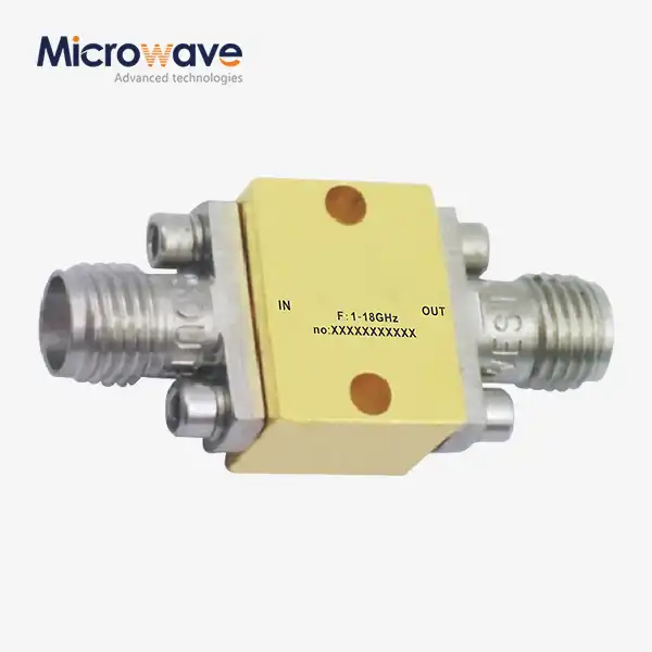
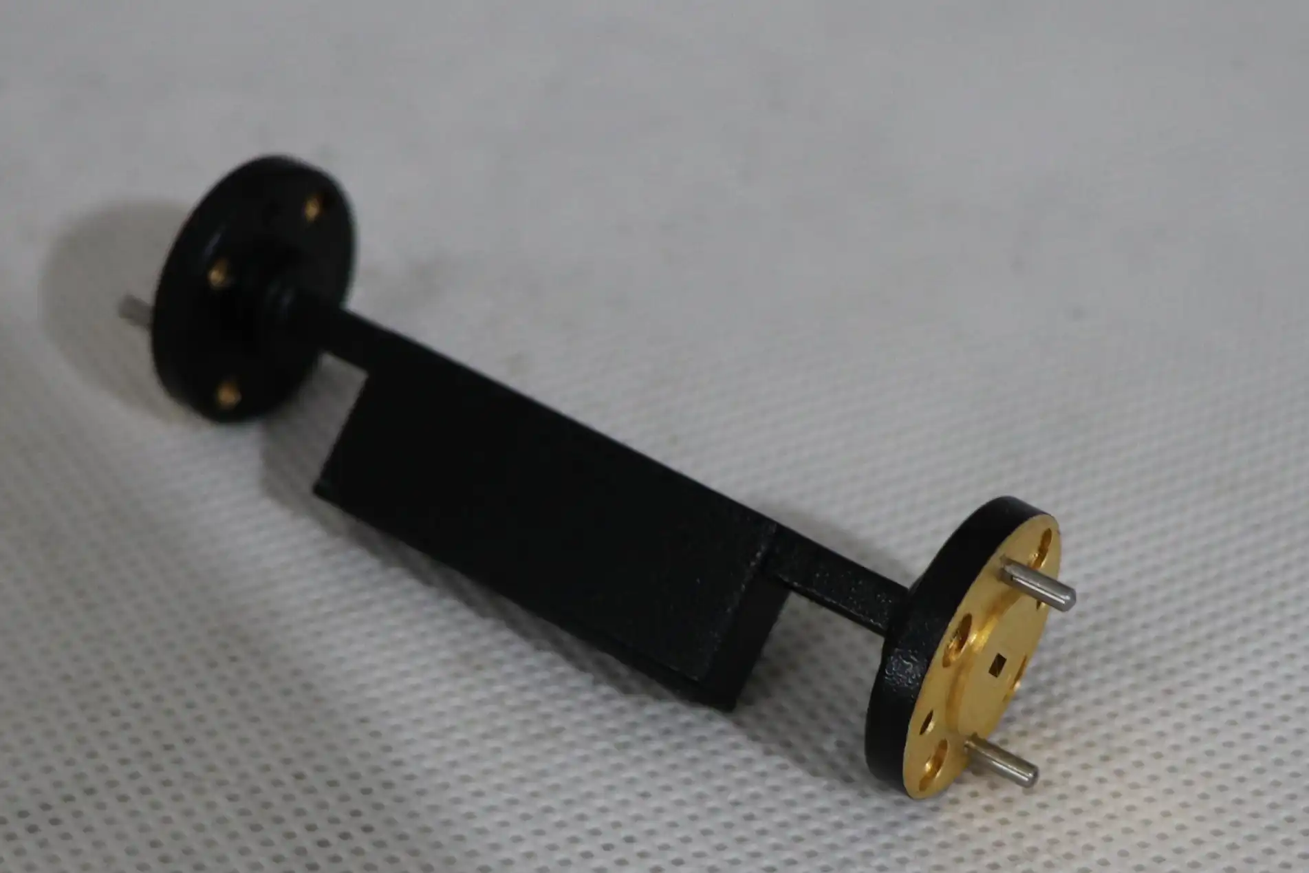
A waveguide fixed attenuator reduces microwave power by a given decibel. A resistive or absorptive element is in the guide's electric field. Extra energy becomes heat. Geometry controls impedance transition. Since the value doesn't vary, the decrease remains constant. No knobs or bumps. Test benches, manufacturing lines, and calibration stages employ these parts since they are reusable. To avoid receiver overload, detector overload, and readings beyond the instrument's linear range, the value must be appropriate.
Attenuation, Insertion Loss, and Isolation Are Different
Buyers confuse these three words. Power is intentionally lowered by 10 dB by attenuation. The power is lost when a line portion is added. A well-matched attenuator should be near to the advertised attenuation. However, a basic waveguide portion shouldn't add much. A circulator or coupler's isolation is how effectively it blocks signals from travelling the wrong way. Read each datasheet section separately and request frequency-specific data instead of a notional number.
Reading the 3 dB to 40 dB Range
You may adjust the level or greatly reduce the transmitter's strength from 3 to 40 dB. Since each 10 dB step lowers power by ten, the values become smaller rapidly. This table shows standard input power.
| Attenuation | Power passed | Typical use |
|---|---|---|
| 3 dB | about 50% | Fine balancing |
| 10 dB | 10% | General signal control |
| 20 dB | 1% | Transmitter testing |
| 30 dB | 0.1% | Strong reduction |
| 40 dB | 0.01% | Strong reduction and protection |
Lower values work well for level control and calibration. Higher values work well for isolating and protecting receivers. No matter which one you pick, make sure you check the signal's tolerance, frequency flatness, VSWR, and whether it is a continuous wave or a pulsed wave.
How to Choose the Correct Attenuation Value
Start With a Power Budget
For a waveguide fixed attenuator, it's simple: necessary attenuation = source power - goal output power, both in decibels. If a transmitter port transmits 50 dBm (100 W), your power sensor can only withstand 20 dBm. Must be 30 dB. The level drops to 10 dBm after adding 40 dB for source volatility, mismatch, and measurement error. This is a working example, so update the values to your datasheet limitations. Then check the attenuator's power. Thus, it must manage 100 W. A part's dB value alone might overheat it.
Do Not Add More Loss Than You Need
Signal quality drops when there is too much attenuation. When placed in front of a receiver, a passive attenuator that isn't frozen adds about the same amount of noise as itself. So, putting a 20 dB pad in front of a low-noise amplifier can really hurt its sensitivity. After a power amplifier or on a test sampling path is a good place for the attenuator. Keep it away from stages with weak signals. A variable attenuator is better for tests that need to be able to change the levels. When the level of reduction needs to stay the same, a fixed attenuator is the best choice.
A Short Decision Sequence
You should explore these choices sequentially. Size and frequency band of WR. Source and target levels determine attenuation. Check power output for continuous, average, peak, and pulsed modes. Measure tolerance, flatness, VSWR, and temperature. Check the flange, connections, dimensions, and installation clearance before purchasing. Check data with an RF engineer for unique or strong designs immediately. Quickly examining the design before the hardware arrives at your bench may save time.
Specifications to Compare Before You Buy
Frequency Span, WR Size, and Interface
Waveguide size is a function of frequency: WR-90, WR-75, WR-62, and WR-28 cover the X-band (8.2 to 12.4 GHz), 10 to 15 GHz, 12.4 to 18 GHz, and 26.5 to 40 GHz, respectively. Size mismatches result in cutoff or higher-order mode propagation. The item size, flange type, and mounting parameters will determine whether SMA coaxial ports are required on the item. Aluminium and copper alloys are heavier and have differing conductivity. State the material and coating.
VSWR, Tolerance, and Power Rating
A unit's reflection performance shows how much it disrupts your system. Return loss is 20.8 dB for VSWRs beyond 1.20:1. Lower VSWR reflects less energy. Attenuation tolerance and flatness must be checked throughout the band, as nominal numbers disguise variances. Rate power by average, peak, pulsed, and continuous wave. Higher temperatures increase heat loss and power derating. Short, intense pulses may cause arcing in even the best thermally rated units. This is because peak power relies on waveguide voltage breakdown. In addition to average values, ask providers for measured data.
Waveguide Fixed Attenuator vs. Other Attenuator Types
A waveguide fixed attenuator can lower a signal in a stable and repeatable way, so it doesn't need to be adjusted. This makes it good for production systems and standard test benches. Variable attenuators work best in tests where the levels change a lot or are controlled automatically. Waveguide attenuators are better for higher microwave frequencies, higher power, or when the system already has waveguide flanges. Coaxial attenuators are easier to install in tighter spaces. You can also pick between one large unit and a group of smaller ones connected in a row. It's easier to keep track of things when they're stacked, but there is more cumulative mismatch and more joints to check. It's usually easier to check if one part is properly rated.
Matching Attenuation Values to Real Applications
Radar and Satellite Communication
Peak power, pulse duration, and duty cycle are all things that radar engineers look at together because thermal limits and breakdown limits are not the same. To get samples down to a level that can be measured, high-power sections often need 20 dB to 40 dB values. As a pad, a waveguide fixed attenuator can also be put between a source and an antenna array. Based on this, a pad of A dB can cut down on apparent return loss by up to 2A dB and protect the source from reflected power. Many times, a loop-back or monitoring path in a satellite earth station needs to lower the uplink power from kilowatts to a level that a spectrum analyzer can handle. There, low VSWR, frequency stability, and environmental resistance are the most important things.
Test Laboratories and Antenna Measurement
A set of 3 dB, 6 dB, 10 dB, and higher units is often kept in laboratories so that they can make controlled signal steps. A standard power sensor is used to test a high-gain amplifier. An attenuator brings the signal into the linear range of the sensor. Then, the readings for gain compression and linearity stay correct, which is important for 5G and millimeter-wave component work. In order to measure and calibrate an antenna, you need test data across the entire operating range, stable attenuation, low reflection, and accurate amplitude response. We know what that data should look like because ADM's labs can measure up to 110 GHz.
Common Selection Mistakes
Four mistakes happen over and over again in buying projects. People choose value over power budget. They forget to check for waveguide compatibility. They think that nominal attenuation is always going to be there across the band. They only look at price. A cheaper part might cost more to integrate, test again, or replace. This is especially true in OEM programs that need consistent documentation and production quality. The exact frequency, WR designation, single-mode range, flange standard, tolerance, flatness, VSWR, and insertion loss should all be checked. Look at the duty cycle, cooling, temperature, vibration, and humidity for both continuous and pulsed operation, as well as the thermal conditions.
Buying, Installing, and Maintaining Your Attenuator
What to Include in Your Inquiry
A clear inquiry speeds up quote accuracy. Share the attenuation, frequency range, WR size, application, input, average, peak, pulse circumstances, VSWR goal, tolerance, temperature range, flange type, dimensions, quantity, and delivery target. Most standard parts ship quicker and are easy to replace. Custom units might have coaxial connections, specific flanges, tiny packaging, or variable power management. You should compare vendors' test results, inspection techniques, export packing, warranties, minimum order quantities, engineering assistance, and evidence of compliance.
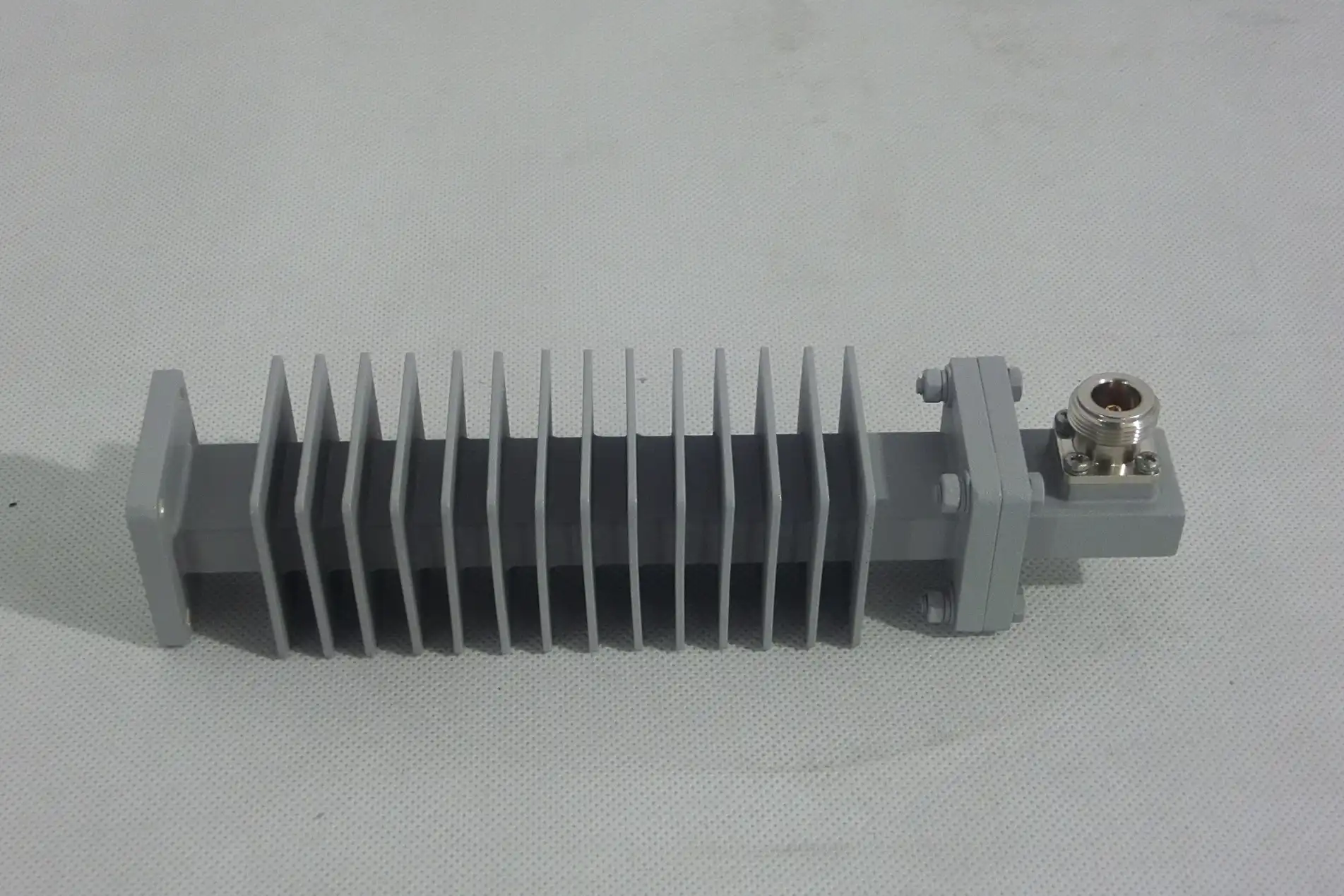
ADM Waveguide Coupling Fixed Attenuator
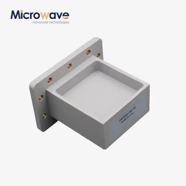
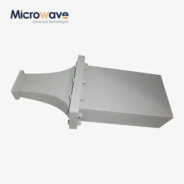
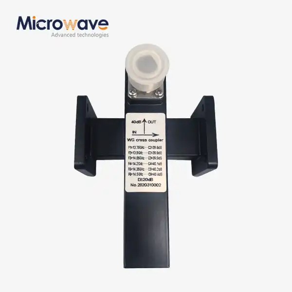
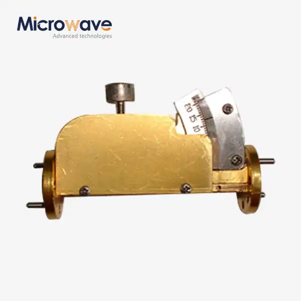
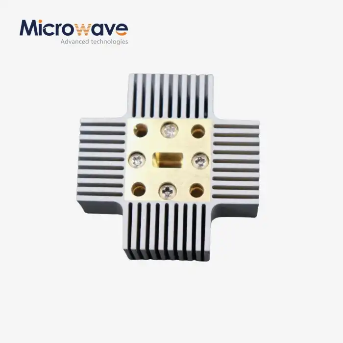
The waveguide coupling fixed attenuator that ADM sells—a waveguide fixed attenuator—is based on a full-band, high-directivity, low-coupling frequency-response coupler. It makes the signal weaker without changing the shape of the waveform. It can be used to control a wide range of signals or as a standard for attenuation in precise measurements. The coupled design comes in both one-way and two-way versions for high-power use. The high-power load is saved on one side of the one-way version, which cuts down on size, weight, and cost. The line works with frequencies up to 110 GHz and waveguide sizes from WR10 to WR230. It is made of copper or an aluminum alloy and has a low VSWR. Satellite communications, radar, aerospace and defense, and telecommunications are all common uses.
Custom OEM Support and Testing Capability
With our custom design service, you can change the waveguide size, attenuation level, and materials to fit your needs. With rapid prototyping, you can test hardware before it goes into full production, and our engineers are here to help with everything from installation to fixing problems. That's backed up by more than 20 years of experience making microwaves, ISO 9001 certification, and products that are RoHS-compliant. Our labs have measuring tools that can handle frequencies up to 110 GHz, and our 24 m microwave darkroom can test antennas from 0.5 GHz to 110 GHz. As much as the part itself, documentation and test support are important for OEM programs. That's why we ask you to share acceptance criteria right away.
Installation, Testing, and Maintenance
Fitting preserves attenuation and prevents mechanical or thermal damage. Check alignment, gaskets, flange surfaces, and fasteners before assembly. Use torque to tighten the hardware. A calibrated vector network analyser can assess operating band attenuation, insertion loss, return loss, and VSWR with documented test conditions and reference-plane correction. While maintaining, check for corrosion, pollution, overheating, discolouration, deformation, and abrupt VSWR fluctuations. Retest after powering up, changing the system, or seeing inconsistent performance.
Conclusion
Before choosing an attenuation value for a waveguide fixed attenuator, construct a power budget: source power minus the following component's safe input level + a margin. Power is reduced ten times each 10 dB increment. A fine balance between strong reduction is possible from 3 to 40 dB. When loss is added, the signal-to-noise ratio decreases; thus, the value should match. The waveguide size, VSWR, tolerance, flatness, and continuous and pulsed power ratings indicate whether a device matches the system. Coaxial, waveguide, and variable kinds may be utilised for testing of various frequencies, power levels, and demands. Some radar, satellite, and lab applications evaluate these aspects differently. Careful installation and testing maintain the intended value.
FAQ
Q1: How much power does a 3 dB or 10 dB attenuator pass?
Whereas 3 dB units will allow roughly half the power in, 10 dB units will admit around a tenth. Each additional 10 dB halves the power; therefore, 20 dB is equivalent to 1% and 40 dB is equal to 0.01%.
Q2: How do I choose between 20 dB, 30 dB, and 40 dB?
Remove the source power from your goal output, add a margin, and verify the thermal rating. Be sure you know the average and peak ratings of the attenuator before you choose a dB number.
Q3: Which waveguide sizes match X-band and Ku-band?
WR-90 is widely used for X-band and operates between 8.2 and 12.4 GHz. The WR-62, operating from 12.4 to 18 GHz, is often utilised for the Ku-band. WR-75 will operate from 10 to 15 GHz. Choose the size depending on how frequently you use it.
Q4: Which specifications should I list for high-power procurement?
Specify VSWR, pulse capability, attenuation tolerance, flange type, test documents required, average and peak power, and temperature range.
Request a Waveguide Fixed Attenuator Quote From ADM
To get ADM to look over your needs, email craig@admicrowave.com with your frequency, WR size, attenuation value, power level, interface, quantity, and delivery target. We are a waveguide fixed attenuator manufacturer with more than 20 years of experience in microwaves. We offer tight quality control, fast delivery, and help with exporting around the world.
References
1. Microwave Engineering (David M. Pozar, Wiley), 2011
2. Foundations for Microwave Engineering (Robert E. Collin, Wiley-IEEE Press), 2001
3. Introduction to Radar Systems (Merrill I. Skolnik, McGraw-Hill), 2001
4. Handbook of Microwave Component Measurements (Joel P. Dunsmore, Wiley), 2012
5. IEEE Std 521, IEEE Standard Letter Designations for Radar-Frequency Bands, 2019
6. IEC 60153-2, Hollow Metallic Waveguides, Part 2: Relevant Specifications for Ordinary Rectangular Waveguides, 2016
_1733809032116.webp)