How Waveguide Termination Prevents Signal Reflection
Waveguide termination serves as a critical passive component in high-frequency RF systems by absorbing electromagnetic energy traveling through waveguides and converting it to heat with minimal reflection. When signals encounter impedance mismatches at the end of a transmission line, they bounce back toward the source, creating destructive interference patterns and standing waves. A properly designed waveguide termination matches the characteristic impedance of the system—typically 50 ohms for coaxial configurations or specific values for rectangular waveguides—ensuring that incident power is absorbed rather than reflected. This protection mechanism prevents damage to sensitive amplifiers, magnetrons, and klystrons while maintaining signal integrity throughout radar, satellite communication, and industrial microwave heating applications.
Understanding Waveguide Termination and Signal Reflection
As electromagnetic waves move through transmission lines, they can reflect signals when they run into sudden changes in resistance. In microwave and radio frequency (RF) systems, these echoes cause voltage standing wave ratios (VSWR) that hurt performance, make power transfer less efficient, and can even damage high-power sources forever. Waveguide Terminations solve this problem by providing a matching load that soaks up energy that comes in at certain frequencies.
The Physics Behind Reflection Prevention
Impedance matching is the basic idea. The reflection coefficient gets close to zero when a Waveguide Termination system ends in a load whose impedance is the same as the line's characteristic impedance. Today's terminations have return loss values higher than 30 dB, which means that less than 0.1% of the power that hits them is sent back to the source. Traveling wave tube amplifiers (TWTA) and solid-state power amplifiers (SSPA) are safe from retroreflection damage that leads to arcing, frequency instability, and catastrophic failure at this level of performance.
Material Science and Design Principles
The power handling needs and frequency bands help engineers choose the right absorber materials. Broadband absorption is provided by carbon-loaded elastomers for low to medium-power uses. Beryllium oxide ceramics, on the other hand, can handle constant power levels of kilowatts in small packages. Whether the absorbing element is pyramidal, wedge-shaped, or curved affects how slowly the resistance changes from the Waveguide Termination's characteristic value to free space. This keeps reflections to a minimum across octave or multi-octave bandwidths.
Impact on System Reliability
Uncontrolled reflections make vector network analyzer (VNA) calibrations less accurate, change the radiation patterns of antennas while they are being characterized, and cause hot spots in high-power transmission systems. To keep radar cross-section readings accurate within ±0.5 dB, defense companies ask for Waveguide Terminations with calibration certificates that can be tracked. These parts are important for satellite ground stations because they protect expensive high-power amplifiers when antennas get damaged by weather or become out of line. This keeps service from stopping, which could cost thousands of dollars per hour of downtime.
Types of Waveguide Termination and Their Applications
Different working situations need different Waveguide Termination plans. For each system design, the selection process finds the best mix between handling power, frequency response, physical size, and environmental toughness.
Fixed Matched Load Terminations
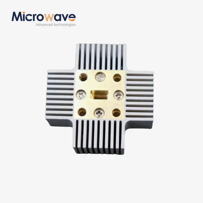
These are the most popular types. They have resistive elements that are permanently placed inside standard waveguide flanges. The designers make them work best with certain frequency ranges, like X-band units that work with 8.2 to 12.4 GHz or Ka-band units that work with 26.5 to 40 GHz. Aerospace projects use toughened versions that are hermetically sealed to survive shock, vibration, and temperature changes from -55°C to +125°C. The absorber material slowly gives off heat to the mounting areas through convection or transfer.
High-Power Water-Cooled Terminations
Industrial microwave devices that make constant waves of power in the kilowatt range need active cooling. There are water lines inside these terminations that take heat away from the ceramic absorbers. This keeps the junction temperatures below dangerous levels. Magnetrons that run at 6 kW of power all the time are used in plasma etch rooms at places that make semiconductors. The cooling system keeps the VSWR below 1.15:1 across the 2.45 GHz ISM band and stops thermal runaway. This keeps plasma production steady for even chip processing.
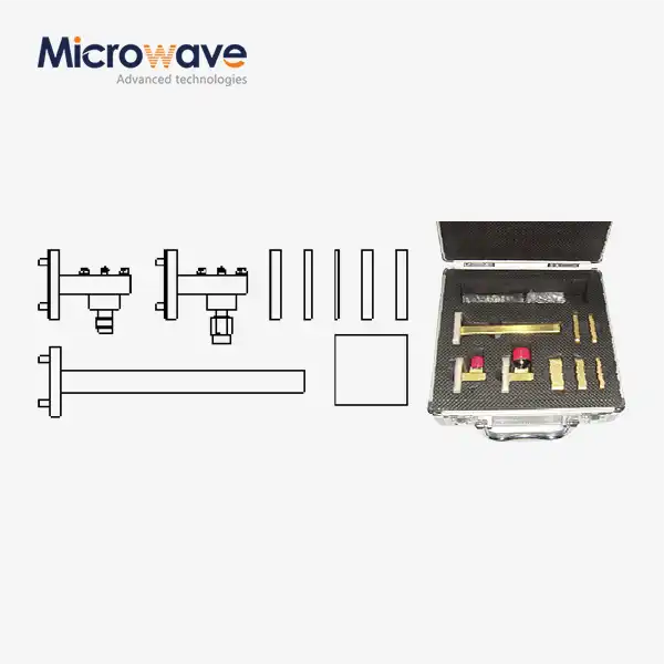
Sliding Terminations for Precision Calibration
In metrology labs, sliding terminations are used. In these, a tapered absorbing element moves lengthwise within the waveguide. This mechanical adjustment changes the phase of residual reflections while keeping their size the same. This lets the ripple method be used to calibrate the VNA. Technicians separate directivity mistakes from real device reflections by measuring reflected signals at multiple locations and then "circle-fitting" the data. This lets them get measurement ranges below 0.01 dB at millimeter-wave frequencies. These tools are used by national standards labs to calibrate reference items for the waveguide business.
These unique designs solve specific problems in the business, defense, and study worlds. The purchasing teams need to check to see if normal catalog items meet the needs or if they need special engineering help to meet the performance gaps.
Comparison of Waveguide Termination with Related Components
There are several inactive parts that handle reflected power, and each one has its own job to do in RF designs. Knowing these differences helps procurement pros come up with the right answers. Waveguide Terminations, while similar to other passive components, serve as unique unidirectional sinks.
Terminations Versus Attenuators
Attenuators lower the intensity of signals in both directions while keeping the system's impedance the same. This lets controlled power levels reach sensitive sensors or test equipment. Waveguide Terminations, on the other hand, work as one-way sinks that take in all energy that comes in while letting very little energy out. A 20 dB filter cuts a 1-watt signal down to 10 milliwatts, but it lets echoes go back through the device. Because terminations get rid of this return line completely, they are only useful for protecting sources and not changing signal levels.
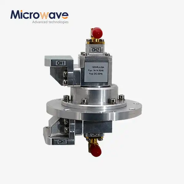
Isolators and Circulator Integration
Ferrite isolators only let power flow in one way by sending reflected power to internal fake loads, which are basically built-in terminations. The main difference is how they work: isolators keep active devices safe while they're normally working, while independent Waveguide Terminations make endpoint loads for ports that aren't being used or for calibration standards. High-power satellite transfer systems use both. An isolator protects the amplifier from antenna reflections, and its isolation port is linked to an external termination that can handle the amount of reflected power. This multiple layer of protection keeps antennas from getting damaged when ice builds up on them or when they point incorrectly.
Dummy Loads in Transmitter Testing
In the business world, dummy loads and Waveguide Terminations are very similar. They both receive RF power without sending it out. The difference is usually about the power level and the situation in which it will be used. When testing FM transmitters, broadcast engineers use dummy loads with a constant power rating of 50 kW. During pulse testing, radar techs use Waveguide Terminations with a peak power rating of more than 1 MW. The way it works is still the same: it shows a matching impedance to stop echoes while safely releasing energy.
How to Choose the Best Waveguide Termination for Your Application?
To choose the best Waveguide Terminations, you need to carefully look at the technical requirements, the supplier's skills, and the business factors that affect the total cost of ownership.
Defining Technical Requirements
Managers of procurement should be able to accurately measure working frequency ranges with enough room for error. To account for component errors and external drift, Waveguide Terminations that are rated for 8 to 12 GHz help a system that runs at 10 GHz. Average and peak power handling must be able to handle both normal operation and fault situations. For example, during impedance transients, a 100-watt average system might see 1-kilowatt peaks. The standards for return loss should be at least 6 dB higher than what the system needs. If the design can handle 20 dB of return loss, then the components should be rated for 26 dB or higher to keep working well across temperature ranges and as they age.
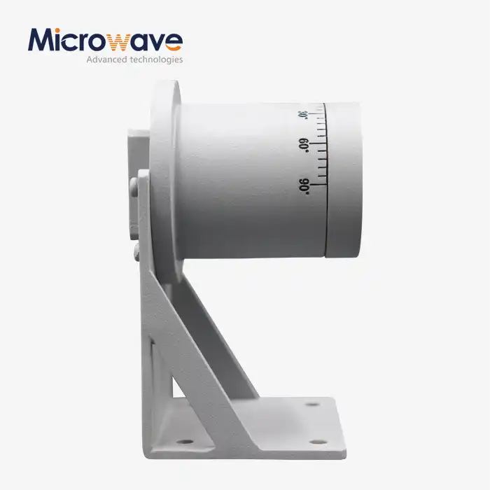
Environmental and Mechanical Considerations
Radar systems in the air need parts that meet MIL-STD-810 standards and can withstand high altitudes, high humidity, and vibrations. MIL-STD-202 says that naval uses need to be resistant to salt fog. Outgassing studies are done on models that are ready for space to make sure that optical systems in satellite payloads don't get contaminated. Because phased array antennas have limited space, small designs may be needed, while lab sets put an emphasis on being easy to connect and making sure measurements are always the same. To keep costs down, mounting configurations—such as flange types like UG, CPR, or special interfaces—must work with the infrastructure that is already in place.
Evaluating Supplier Credentials
Leading makers use ISO 9001 quality systems that keep track of raw materials and testing standards. ADM's 24-meter anechoic room lets us measure far-field antennas up to 110 GHz. This gives us proof data that shows that all of our products work as they should. Our research team has more than 20 years of experience with waveguide assemblies and can suggest the best designs for use in defense, aircraft, satellites, and industry. Custom solutions are tested as thoroughly as stock items, so the performance is the same whether you order a single sample or a lot of them for production.
Commercial Terms and Lead Times
Standard catalog Waveguide Terminations usually ship in two weeks, but unique patterns can take anywhere from four to eight weeks, based on how complicated they are. When you buy more than 25 units, the price per unit goes down, and you can get even bigger savings if you agree to a long-term supply deal. Integration risks are lower when there is technical support throughout the procurement cycle. For example, our engineers help with reviewing specifications, provide 3D CAD models for mechanical integration, and offer measurement proof methods. By working with sellers who keep enough inventory on hand, you can avoid problems in the supply chain that could push back important program goals.
Best Practices for Installation and Maintenance to Maximize Performance
Handling and putting together components correctly protects their purity and ensures they work as expected electrically throughout their working life. Proper installation of a Waveguide Termination is essential to maintain low VSWR.
Installation Guidelines to Minimize Reflection
For flange connections to work, the torque must be applied evenly and according to the manufacturer's instructions. For small waveguide sizes, this torque should be 15 to 25 inch-pounds, but it can go up to 40 inch-pounds for bigger cross-sections. When bolts are tightened unevenly, air holes form that make VSWR worse and cause passive intermodulation distortion. Use lint-free brushes and isopropyl alcohol to clean the connecting surfaces and get rid of any dirt or oxidation. When you touch gold-plated objects with your bare hands, the transmission decreases over time because of skin oils. When linking pressurized waveguide systems, make sure that the gaskets work with the environmental covers to keep the altitude ratings.
Periodic Testing and Verification
Vector network monitors give the most complete picture of how well a Waveguide Termination works. After setting up, check the S11 values across the working band to make sure the return loss meets the requirements. Set up starting points for comparisons during regular maintenance periods, which are usually once a year for business systems and every three months for defense uses. A sudden drop in return loss is often a sign of moisture getting in, damage from mechanical shocks, or heat stress from too much power. If you catch these problems early, you can keep expensive radio parts from getting damaged again.
Storage and Handling Protocols
To keep metal surfaces from rusting, store Waveguide Terminations in places with controlled humidity below 60% RH. Protective end caps should be put on flanges when they are not being used to keep them clean and avoid mechanical damage. Do not drop or hit the units, as the internal absorber parts can break, causing impedance gaps. For high-power terminations with cooling systems, the water lines need to be checked every so often for scale buildup or bacterial growth. Flushing cooling loops once a year with pure water and inhibitors keeps thermal transfer working well and stops hotspots from forming, which shortens the life of the absorber.
Conclusion
Waveguide Terminations are important parts of current RF systems because they protect the signals and set the standards for tuning. Because they can absorb electromagnetic energy with little reflection, they protect expensive amplifiers, allow accurate readings, and make sure that mission-critical apps work reliably. To choose parts that meet both short-term and long-term dependability needs, procurement workers have to look at both technical specs and the supplier's abilities. When installed correctly and tested on a regular basis, these passive devices can last for decades without any upkeep, saving much more valuable active electronics. Quality terminations only cost a small part of the total cost of the system, but they keep major failures from happening that could mean mission failure or expensive fixes.
FAQ
Q1: What frequency ranges do waveguide terminations typically cover?
The frequency ranges of standard store items cover 1 GHz to 110 GHz. The most popular ranges are S-band (2-4 GHz), C-band (4-8 GHz), X-band (8-12 GHz), Ku-band (12-18 GHz), Ka-band (26.5-40 GHz), and V-band (50-75 GHz). For 5G infrastructure and car radar, specialized millimeter-wave models go into the W-band (75–110 GHz). To keep the return loss performance the same, each design uses the best absorber shape and materials for a certain range of wavelengths. Waveguide Terminations are specifically optimized for these bands.
Q2: Can waveguide terminations be customized for specialized applications?
Manufacturers offer a wide range of customization options, such as non-standard flange connections, weather protection for high temperatures, built-in cooling systems for high-power uses, and loads that are precisely matched for metrology. Custom Waveguide Termination projects usually need a lot of specifics, like the frequency range, power handling, VSWR limits, weather conditions, and physical limitations. Engineering teams check to see if something is possible, guess how well it will work, and make prototypes before starting mass production.
Q3: How can I verify termination performance after installation?
Vector network monitors directly measure return loss by measuring the power that is reflected to the power that comes in across frequency sweeps. Use accuracy standards to set the VNA's parameters, then join the Waveguide Termination and record the S11 value. Values should stay below the limits given, which are usually -20 dB or higher. If problems happen, time-domain reflectometry can find exact spots where impedance breaks happen. Using thermal imaging during high-power operation shows that the heat is spreading evenly and there are no areas that could mean internal damage.
Partner with ADM for Reliable Waveguide Termination Solutions
Advanced Microwave Technologies Co., Ltd. makes high-quality Waveguide Termination parts and has been making microwaves for over 20 years, and is ISO 9001 certified. Defense companies, satellite system developers, and research institutions that need proven performance and strict quality control use our wide range of products. Our technical team helps with applications from the first review of the design all the way through production delivery. They can find standard stock terminations or make custom solutions for special needs. As a reliable Waveguide Termination maker, we offer cheap pricing, quick prototype turnaround, and global logistics services that make buying easier for projects that need to be finished quickly. Email craig@admicrowave.com right away to talk about the needs of your project, ask for performance numbers, or set up a technical meeting with one of our engineers.
References
1. Pozar, David M. "Microwave Engineering, Fourth Edition." John Wiley & Sons, 2011.
2. Saad, Theodore S. "Microwave Engineers' Handbook, Volume 1: Components and Devices." Artech House Publishers, 1971.
3. Collin, Robert E. "Foundations for Microwave Engineering, Second Edition." IEEE Press, 2001.
4. Harvey, A. F. "Microwave Engineering Handbook, Volume 2: Materials and Components." Academic Press, 1963.
5. Baden Fuller, A. J. "Microwave Measurements, Third Edition." Institution of Electrical Engineers, 2000.
6. IEEE Standard 1785-2012. "IEEE Standard for Rectangular Metallic Waveguides and Their Interfaces for Frequencies of 110 GHz and Below." Institute of Electrical and Electronics Engineers, 2012.