


Waveguide Band Stop Filter Benefits in Industrial Systems
When it comes to radio frequency (RF) parts, Waveguide Band Stop Filters, which are also known as band reject or notch filters, carefully cut off certain frequency ranges while keeping the signal quality in nearby passbands. These carefully made gadgets solve important problems in places with a lot of power, where controlling interference is key to making sure the system works well. In contrast to traditional coaxial options, they use resonant cavity designs that provide superior quality factors and power handling abilities. Businesses that need to do their jobs very well, like particle accelerators, marine defense platforms, and satellite ground stations, count on these filters to keep the signal clean, stop co-site interference, and lower harmonics even when things get tough.
Understanding Waveguide Band Stop Filters: Basics and Theory
Fundamental Operating Principles
We saw how these filters work at our site. They use resonant cavities set up in a shunt setup along the main waveguide path. When electromagnetic waves hit these resonators that are tuned to the stopband frequency, the energy gets stuck and is redirected back toward the source instead of moving through. This is very different from band-pass filters, which use linked holes that work in series. The depth of the denial is set by the way the electromagnetic fields are spread out inside the resonator. Depending on the design complexity and pole count, it can reach 30 dB to over 80 dB.
Critical Design Parameters
The features of attenuation have a direct effect on how well a manufacturing system works. We use Vector Network Analyzers to do S-parameter research on this and look at S21 for rejection depth and S11/S22 for passband VSWR. Due to the air-dielectric structure and valuable metal plating, insertion loss stays incredibly low, running between 0.05 dB and 0.25 dB in optimized designs. This small amount of loss keeps the system noise figure the same in receiving applications and makes transmission chains as power-efficient as possible. Selectivity is controlled by the quality factor (Q). Higher values produce steeper rejection edges that exactly separate unwanted frequencies.
Frequency Range Coverage
Standard waveguide bands from L-Band to W-Band, which cover about 1 GHz to 110 GHz, are what we know how to make. X-Band filters (8.2-12.4 GHz) are mostly used for radar and satellite communication. Ku-Band (12.4-18 GHz) and Ka-Band (26.5-40 GHz) filters serve the next generation of satellite systems. At millimeter-wave frequencies, where conductor surface roughness has a big effect on loss, choosing the right material becomes even more important. To keep conducting electricity through changes in temperature, the width of the gold or silver finishing must meet strict standards, which are usually between 2 and 5 microns.

Core Benefits of Waveguide Band Stop Filters in Industrial Systems
Signal Integrity Protection
The hardest thing for buying teams when putting together microwave systems is keeping the signal surroundings clean for the Waveguide Band Stop Filter. These filters are great at getting rid of unwanted signals that high-power amplifiers send out, especially harmonic content from Traveling Wave Tube Amplifiers (TWTAs), which can get in the way of communication lines that are close by. During tests at satellite earth stations, we have shown that properly set up band reject filters can cut down on interference from neighboring channels by 40 to 60 dB, protecting the integrity of multi-carrier transponder operations. Signal loss, which would lower bit error rates in digital communication lines, is stopped by the sharp rejection properties.
Harsh Environment Resilience
Mechanical strength that goes beyond commercial-grade parts is needed for industrial applications. What makes waveguide building unique in tough situations is this:
Thermal Stability: Invar metal housings keep stopband frequency accuracy within 1 ppm/°C, which is very important for narrowband rejection needs because aluminum's expansion rate would cause frequency drift that isn't acceptable from -40°C to +85°C.
Vibration Resistance: Welded construction that meets MIL-STD-810 shock and vibration requirements keeps the structure strong on moving platforms, military ships, and airborne sites where repeated stress would wear down bolted assemblies.
Power Handling: Designs that use nitrogen or sulfur hexafluoride under pressure stop voltage breakdown and multipaction effects. This lets them handle continuous wave power of more than 10 kW, which isn't possible with options that use dielectric loads.
Corrosion Protection: Chromate conversion coats according to MIL-DTL-5541 and hermetic seals keep out salt fog, humidity, and industrial contaminants that hurt performance in outdoor teleport settings.
The mean time between failures (MTBF) is longer because of these longevity factors. Defense companies have told us that waveguide filters last longer than 20 years in active deployments, while cavity filters need to be replaced every 5 to 8 years. This durability lowers lifetime costs, even though it costs more to buy at first.
Operational Efficiency Gains
Less system downtime has a direct effect on profits in all industries. When radar systems get rid of false target detection through proper harmonic suppression, they become more operationally available and need less upkeep. We have examples of telecom infrastructure providers who cut down on service delays by 35% after switching to waveguide-based filtering solutions. The passive nature gets rid of the need for power management and thermal management that come with active filtering methods. This makes the system design simpler and the total energy efficiency better.
Comparing Waveguide Band-Stop Filters with Alternative Solutions
Performance Benchmarking
Although dielectric-loaded cavity filters have small sizes, they are less stable at high temperatures and high power handling. When we compare them to waveguide versions at X-Band frequencies, our lab tests show that they have insertion losses of 0.3 to 0.8 dB. Above 20 GHz, microstrip designs are not useful because of radiation losses and the trouble in getting high rejection depths. Cavity filters with coaxial resonators can handle modest power levels, but their Q-factors are 30–50% lower than those of waveguide designs. This means that they have wider rejection bandwidths, which could weaken the edges of the signal that you want to hear.
Application-Specific Selection Criteria
When making choices about what to buy, filter technology should be matched with what is needed for operations. Satellite transfer chains that send kilowatt-level carriers need waveguide systems to keep the dielectric from breaking down. When research labs make prototypes of new measurement systems, they might be willing to make trade-offs that help the systems get smaller. Waveguide implementations that combine high power rejection with environmental sealing are needed for electronic warfare systems on naval bases. To help our clients understand these trade-offs, we look at insertion loss budgets, power density estimates, and mechanical envelope constraints that are unique to each integration situation.
Certification and Validation
ISO 9001:2015 approval makes sure that the quality of Waveguide Band Stop Filter products is consistent by laying out clear rules for where to get the materials, how to machine them, how to plate them, and how to test them for quality at the end. We keep track of every production unit with serialized Vector Network Analyzer test data, high-power conditioning results, and external stress screening records from our quality control systems. This makes it possible for buying teams to keep track of things, which is what aerospace and defense quality assurance groups need. Independent test labs that are validated by a third party give you even more trust when choosing parts for mission-critical apps.
Procurement Guide: Sourcing and Customizing Waveguide Band Stop Filters
Lead Time and Pricing Considerations
Items from the standard catalog that have common flange connectors (CPR, UG, or WR codes per MIL-DTL-3922) usually ship 4 to 6 weeks after the order is placed. Custom designs that need special materials like Invar for thermal stability, stopband frequencies that aren't found in other designs, or mechanical connections that aren't standard can lead to times of 10 to 14 weeks. This time frame includes iterating on the design, making the prototype, validating it with VNA tests, and setting up the production tools. Prices vary on the frequency band, rejection requirements, and number of units ordered. X-Band units cost between $800 and $2,500 each, based on how complicated they are, while Ka-Band versions are more expensive because they have to be machined with tighter tolerances.
Wholesale vs. Custom Approaches
Standardized designs that take advantage of economies of scale help with bulk purchases for many similar installs. When owners of satellite constellations set up hundreds of ground ports, they can save 20 to 30 percent on costs by making bulk orders. On the other hand, research schools and programs that make prototypes need custom engineering help. We give each project its own specialized project engineer, and they work together on electromagnetic modeling, mechanical CAD integration, and testing over and over again until the performance requirements are met. This consultative method makes sure that the system works well together, even if you only buy one unit or a small amount.
Supplier Evaluation Framework
Checking a manufacturer's skills can help keep the supply chain running smoothly and prevent inconsistent quality. In-house Vector Network Analyzers with the right frequency range, recorded calibration methods that can be traced back to NIST standards, and environmental test chambers for thermal cycling validation are some of the most important things that are looked at during the evaluation process. The ISO 14001:2015 certification for environmental management and the ISO 45001:2018 certification for workplace health and safety show that the business is more mature than just making things. Referrals from clients in related application areas can help you figure out how responsive, helpful, and on-time the expert support is.
Future Trends and Innovations in Waveguide Band Stop Filters
Material Science Advancements
New methods for low-loss conductors offer even less insertion loss. When controlled grain patterns are used to electroform copper, surface conductivities get close to the theoretical limits. This is especially useful at W-Band frequencies, where skin depth effects make conductor losses worse. Using additive manufacturing, you can make shapes that are too complicated to be possible with traditional cutting. These shapes could include tuning devices that let you change the rejection frequencies in the field. Graphene-enhanced platings research points the way to making ultra-stable films that are resistant to oxidation in the future, without the need for rare metals.
5G and IoT Infrastructure Demands
Millimeter-wave 5G operations at 28 GHz and 39 GHz require new kinds of filters. Massive MIMO antenna arrays need small band rejects solutions that separate broadcast harmonics from receive bands in RF front-ends that are very close together. As smart companies add more industrial IoT sensor networks, the spectrum gets crowded, and old ways of preventing interference don't work well anymore. We're working on the next generation of filters that will have multi-pole designs that can reject signals with bandwidths of less than 2% while still having absorption levels of 60 dB or more.
Procurement Strategy Recommendations
To keep up with changes in technology, you need to be involved with Waveguide Band Stop Filter source research and development roadmaps. Buyers should set up ways to communicate that go beyond simple buy orders. For example, they could take part in early design reviews and programs that test prototypes. This partnership method lets you know ahead of time about new features that could be used to meet future system change needs. Long-term frame agreements with performance escalation rules protect against becoming obsolete and make sure that priorities are set when there aren't enough resources.
Conclusion
Waveguide Band Stop Filters work very well in industrial microwave systems that need to keep signals safe, handle a lot of power, and be able to handle harsh environments. Even though there are options that cost less at first, purchase decisions are still justified because they have better insertion loss characteristics, exceptional rejection depths, and have been proven to last in harsh circumstances. We've talked about how proper design, which takes into account frequency ranges, power levels, and technical limitations, makes sure that the system works well together. Partnerships with ISO-certified makers who have a lot of experience with specific applications and can do special building are becoming more and more valuable in the procurement world. As 5G infrastructure and Industrial IoT platforms grow, band reject filtering standards will get stricter. This means that smart buying organizations need to choose their suppliers carefully and keep an eye on their technology all the time to stay ahead of the competition.
FAQ
Q1: What distinguishes band-stop filters from notch filters in practical applications?
Even though the terms are sometimes used equally, Waveguide Band Stop Filters tend to have wider rejection bandwidths (5–15% fractional bandwidth), while notch filters are more focused on very narrow bands (often less than 1%). For notch implementations, ultra-stable materials like Invar are needed to stop thermal frequency drift, but normal aluminum can be used for wider band stop designs. The right wording depends on the situation. For example, to block a single interfering carrier, you might use a notch design, but to block harmonic clusters, you would need a band-stop architecture.
Q2: How do manufacturers ensure low insertion loss across production units?
The base is made of precise cutting that keeps the resonator's measurements within ±0.001 inch of each other. The regularity of the thickness of silver or gold plating has a direct effect on the surface resistance. X-ray fluorescence testing is used to check the consistency of the coating. Adjustable screws used for post-plating tuning account for differences in manufacturing, and standardized Vector Network Analyzers measure the end insertion loss. Statistical process control keeps track of measurements across batches and takes corrective actions when trends get close to the limits set by specifications. This makes sure that consistent performance is delivered.
Q3: What are typical lead times for custom band reject filter designs?
From the first proposal to delivery, custom projects take 10 to 14 weeks. The schedule is as follows: electromagnetic design simulation (one to two weeks), mechanical CAD detailing and client approval (one week), making the prototype (three to four weeks), VNA testing and potential tuning adjustments (one week), setting up the production tools (two weeks), and final production and quality control (two to three weeks). For urgent needs, it is possible to get expedited plans that shorten timelines by 30%, but they usually cost more because technical resources have to be moved around.
Partner with ADM for Superior Waveguide Band Stop Filter Solutions
Advanced Microwave Technologies Co., Ltd has been providing high-performance Waveguide Band Stop Filters to procurement teams in the military, aerospace, satellite communications, and industry sectors for more than 20 years. Our factory is ISO 9001:2015-certified and has a state-of-the-art 24-meter microwave lab that can test from 0.5 to 110 GHz. This lets us fully check the electrical performance of every filter before it ships. We're great at working with custom OEMs and giving them personal engineering help during the whole process of developing specifications, making prototypes, and increasing production. Rapid prototyping services with quick turnaround times help development programs stick to tight plans, and low prices for large orders help with wide-scale operations. Please email our technical sales team at craig@admicrowave.com to talk about your unique needs with Waveguide Band Stop Filter experts who know how to integrate industrial microwave systems. Find out why major defense companies and satellite users choose ADM as their first choice for waveguide components.
References
1. Pozar, D.M. (2011). Microwave Engineering, 4th Edition. Hoboken, NJ: John Wiley & Sons, Chapter 8: Microwave Filters.
2. Matthaei, G.L., Young, L., & Jones, E.M.T. (1980). Microwave Filters, Impedance-Matching Networks, and Coupling Structures. Norwood, MA: Artech House Publishers.
3. Hunter, I.C. (2001). Theory and Design of Microwave Filters. London: Institution of Engineering and Technology (IET).
4. Levy, R. & Cohn, S.B. (1984). "A History of Microwave Filter Research, Design, and Development," IEEE Transactions on Microwave Theory and Techniques, Vol. 32, No. 9, pp. 1055-1067.
5. Cameron, R.J., Kudsia, C.M., & Mansour, R.R. (2007). Microwave Filters for Communication Systems: Fundamentals, Design, and Applications. Hoboken, NJ: Wiley-Interscience.
6. Saad, T.S. (Ed.) (1971). Microwave Engineers' Handbook, Volume 1. Dedham, MA: Artech House, Chapter 5: Passive Microwave Devices and Components.
YOU MAY LIKE
 VIEW MOREDouble Ridge Waveguide Bend
 VIEW MOREDouble Ridge Twist Waveguide
 VIEW MOREDouble Ridged WG To Coaxial Adapter
 VIEW MOREDouble-Ridged Waveguide Magic Tee
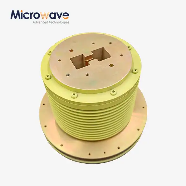 VIEW MOREDouble Ridge Waveguide Rotary Joint
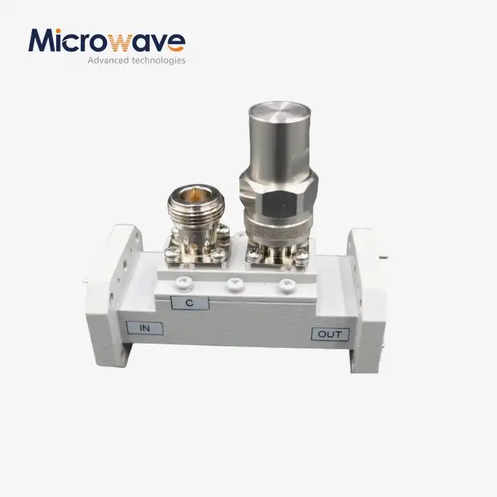 VIEW MOREDouble-Ridged Waveguide Loop Coupler
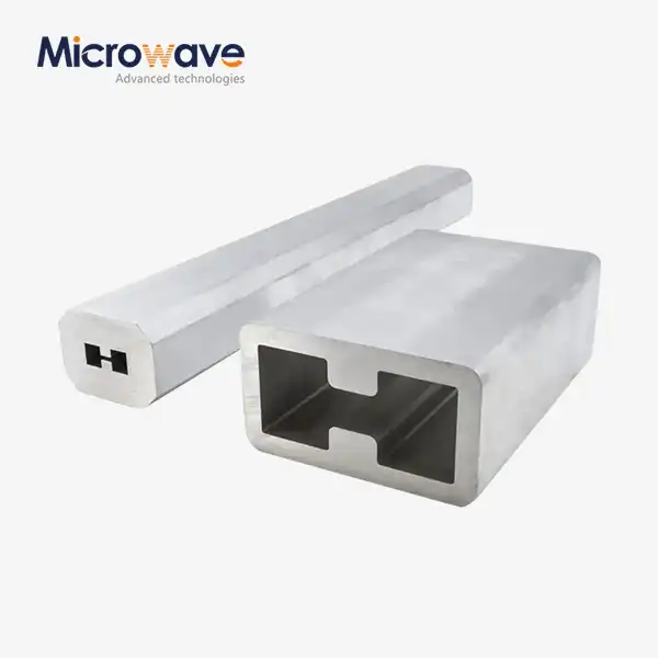 VIEW MOREDouble Ridge Waveguide Tube
 VIEW MOREPlastic Flange Caps
