How to Specify a Waveguide Cable Assembly for mmWave Systems
Choosing a waveguide cable assembly for millimeter-wave (mmWave) systems is more than a product number in a catalog. Signal integrity at frequencies beyond 18 GHz, as high as 110 GHz for sophisticated radar and satellite applications, relies on matching every physical and electrical aspect to the precise needs of your system. A well-designed flexible waveguide assembly avoids the insertion loss penalty associated with coaxial alternatives, can handle larger power levels, and withstand severe mechanical conditions. This book leads B2B procurement engineers through each decision point, from frequency band selection to flange standards, so you know you’re getting the appropriate component the first time.
Understanding Waveguide Cable Assemblies and Their Role in mmWave Systems
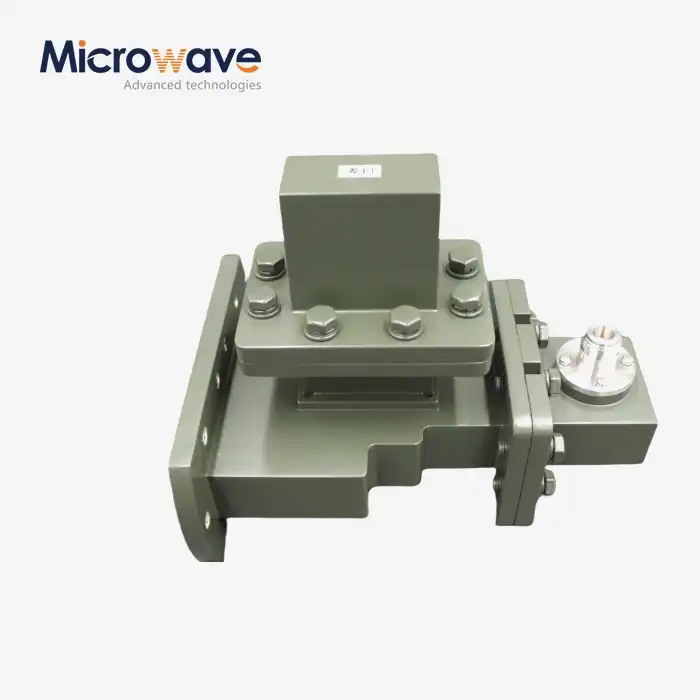
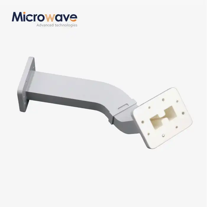
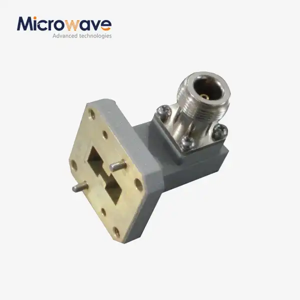
Before writing a specification, it's helpful to know what makes a waveguide cable assembly different from other types of transmission media and why that's important at mmWave frequencies.
How Waveguides Propagate Signals
Waveguides carry electromagnetic energy in TE or TM modes via a hollow metal tube, while coaxial wires carry data in TEM mode between a central conductor and a shield. With no center conductor to contribute resistive loss, the attenuation is extremely low, frequently less than 0.5 dB/m, at frequencies when coax performance drops substantially.
Frequency Bands Covered by Standard WR Sizes
Each waveguide size is suitable for a certain range of frequencies. The WR-90 operates in the X-Band 8.2-12.4 GHz, the WR-28 operates in the Ka-Band 26.5-40 GHz, and the WR-10 operates in the W-Band 75-110 GHz. The first step in any standard for 5G mmWave infrastructure and satellite ground stations operating in Ku, K, and Ka bands is to choose the correct WR designation.
Rigid vs. Flexible Configurations
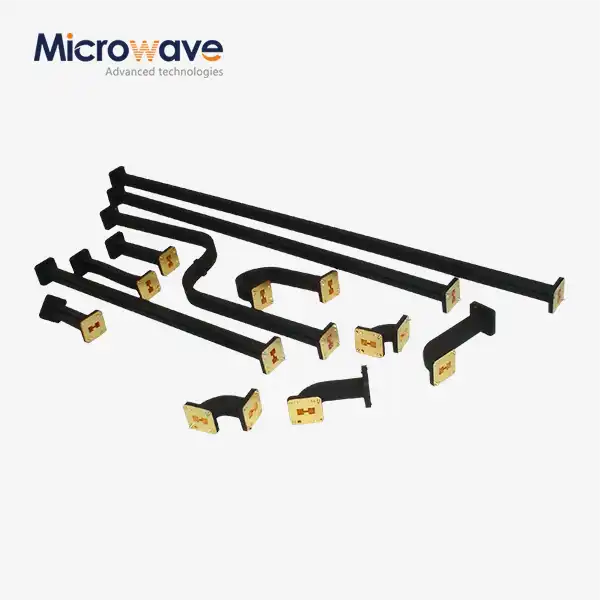
Rigid waveguide sections offer the least loss and can withstand the maximum power. However, they cannot absorb vibrations or correct for misaligned ports. A flexible waveguide system has a twisted, interlocking core to provide some mechanical flexibility. The core is made of silver-plated copper or brass. The twistable versions enable bending and rotation around the axis and bending in the E- and H-planes, which are needed for gimbaled antenna feeds in airborne radar systems.
Key Factors to Consider When Specifying Waveguide Cable Assemblies
Once they understand the foundations of how the system works, purchasing engineers have to look at a variety of aspects that influence each other before they agree to a design.
Frequency Range and Insertion Loss Budget
The link budget of your system determines the maximum allowable insertion loss. A typical flexible waveguide cable assembly at 40 GHz has about one twentieth the insertion loss of a comparable high-performance coaxial wire. Make that the rated attenuation of the assembly across the whole working band doesn’t exceed your budget. Also, the VSWR should be less than 1.25:1 to transmit high power efficiently.
Material Selection and Environmental Resistance
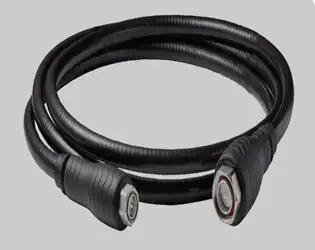
The twisted core is commonly silver-plated copper or brass for conducting electricity and resisting corrosion. The top jacket requires the proper material. For outdoor SATCOM ground stations where temperature variations are expected, jacketing in neoprene or silicone (per MIL-DTL-3922) is good, while polished metal-only construction is preferable for vacuum rooms where minimum outgassing is required.
Minimum Bend Radius and Mechanical Integration
There is a Minimum Bend Radius (MBR) specified on every item. The MBR of a WR-75 unit is about 65 mm. Exceeding this limit will cause irreversible damage to the interlocked convolutions and VSWR spikes. For tiny flying platforms, weight and dimensions are also important. Always distinguish between static MBR (one installation bend) and dynamic MBR (multiple flex cycles), and compare the claimed flex-cycle life of the assembly to the duration between repair cycles.
Comparison of Waveguide Cable Assemblies vs. Alternative Solutions
At mmWave frequencies, purchasing managers often want to know if a high-end coaxial line or a fiber-based option can be used instead of a waveguide. The answer relies on the frequency, the amount of power, and the limits of the space available.
Here's how the three technologies stack up in the areas that matter most for B2B mmWave procurement:
- Insertion loss at 40 GHz: Flexible waveguide assemblies deliver roughly 0.3–0.5 dB/m. Premium coaxial cables in the same band typically exceed 3–5 dB/m, a significant penalty for high-power radar or satellite uplinks.
- Power handling: Waveguide structures carry kilowatt-level CW power without thermal failure. Coaxial cables at the same frequency are limited to tens of watts before the center conductor heats dangerously.
- Phase stability under flexure: High-end flexible waveguide assemblies hold phase variation within ±2° to ±5° during bending, which is critical for phased array radars and Vector Network Analyzer (VNA) measurements. Coaxial cables show larger phase drift under mechanical stress.
If you want to send data in SATCOM earth stations, overhead radar feeds, or mmWave test benches, waveguide systems are the best way to do it. Coaxial options are still useful for lower-frequency receive lines or tight routing inside spaces with a lot of people. When making a procurement decision, it's important to match the technology to the application instead of just using one format.
How to Select the Right Waveguide Cable Assembly Manufacturer and Supplier
Picking the best waveguide cable assembly supplier impacts not only price, but also lead time, the quality of the documentation, and the continuity of long-term supply.
Certifications and Manufacturing Standards
In order to be a supplier, you should at least have ISO 9001:2015 certification. Buyers in defense and aircraft should also make sure that the documents they receive are compliant with RoHS and can be tracked. Suppliers who can do VNA tests in-house (up to 110 GHz) can include full-band sweep data as a shipment deliverable. This speeds up inspection upon arrival and lowers the risk of integration failure.
Customization and OEM Capability
Standard store things don't always meet all the needs of mmWave systems. Check to see if the seller can quickly make a prototype, change the labels on the flanges to CPR, UBR, UG, or MIL, and provide OEM-ready paperwork packages. If a supplier does both research and production in-house, they can change the core dimensions, jacket materials, and flange configurations to directly match your interface drawings.
After-Sales Support and Supply Chain Reliability
Technical support is important after the sale. Find out about the guarantee, how failures are analyzed in the field, and whether the supplier's tech team can help with installation or fixing problems. For projects that need a lot of parts, make sure the provider can increase the number without changing the electrical or size tolerances.
Installation Best Practices and Design Guidelines for Optimal Performance
Even a correctly described part won't work right if it's put together without care. Following a strict installation process protects both the part being installed and the system as a whole.
Impedance Matching and Flange Interface Integrity
Field problems often happen because the flanges don't match up right. When a covered flange is joined incorrectly to a grooved flange, RF leaks and impedance discontinuities happen. Before putting the parts together, you should always check the exact flange standard, which could be PBR, UBR, CBR, or the right MIL-spec UG designation. Check the position of the bolt holes with precise GO/NO-GO gages, and make sure the flange face is flat to stop arcing at high power.
Routing, Bending, and Secure Mounting
Move the parts around so that no bends are less than the maximum MBR. To stop wind- or vibration-related fatigue, use tie-down brackets at the intervals suggested in the supplier's datasheet. Do not let the unit carry its own weight over unsupported spans; too much mechanical stress at the flange joints is a major reason why they fail before they should.
Maintenance, Inspection, and Replacement Criteria
Set up regular VNA spot checks on installed assemblies that will be used in high-cycle situations, like rotating radar feeds. Flag parts that show VSWR increases greater than 1.35:1 or insertion loss increases greater than 10% of the norm as shipped for replacement. For outdoor waveguide runs that are under pressure, you should check for nitrogen leaks every time you do maintenance to make sure the jacket and flange seals are still good.
Conclusion
It is a structured process to choose a waveguide cable assembly for mmWave systems: you must confirm your frequency band and WR size, set your insertion loss and VSWR budget, match the materials and jacket type to the operating environment, check the MBR against your routing constraints, and pick a supplier that sends certified documentation with the hardware. Every choice builds on the one before it. When all the factors are right, the assembly becomes a clear link in your RF chain and does exactly what the system needs it to do, from the time it is first put together until years of service.
FAQ
What frequency ranges do waveguide cable assemblies cover?
Standard WR-designated assemblies cover frequencies from roughly 1 GHz (WR-650) up to 110 GHz (WR-10). Most mmWave procurement falls within WR-28 (Ka-Band, 26.5–40 GHz) through WR-10 (W-Band, 75–110 GHz). Your system's operating frequency determines the correct WR size.
How does bend radius affect electrical performance?
Bending an assembly beyond its rated MBR distorts the interlocking convolutions and creates impedance discontinuities that appear as VSWR spikes across the operating band. Dynamic bending applications—such as rotating antenna feeds—require the assembly to meet a dynamic MBR rating and a confirmed flex-cycle life, which differs from the static installation MBR.
Can I order a custom waveguide assembly for a non-standard interface?
Yes. Manufacturers with integrated design and production capability can produce assemblies with custom flange configurations, non-standard lengths, specific jacket materials, or vacuum-compatible construction. Provide your interface drawing, operating frequency, power level, and environmental requirements when requesting a quote. Prototype delivery ahead of production commitment is standard practice for custom orders.
Partner With ADM for Your Next Waveguide Cable Assembly Order
Advanced Microwave Technologies Co., Ltd. (ADM) has been making things for more than 20 years and brings that knowledge to every waveguide cable assembly order. Our VNA measurement lab works up to 110 GHz, and all of our assemblies come with full-band sweep data. We offer OEM customization and direct engineering consultation, and we support compliance with ISO 9001:2015 and RoHS. To get a price, email craig@admicrowave.com. You can do this whether you need a single sample or a thousand units.
References
1. Pozar, D. M. Microwave Engineering, 4th ed. Wiley, 2011.
2. Ollin, R. E. Foundations for Microwave Engineering, 2nd ed. IEEE Press / Wiley-Interscience, 2001.
3. MIL-DTL-3922, Flanges, Waveguide (Flat and Grooved Types), General Specification for. U.S. Department of Defense, 2003.
4. IEEE Standard 1785.1, IEEE Standard for Rectangular Metallic Waveguides and Their Interfaces for Frequencies of 110 GHz and Above. IEEE, 2012.
5. Montgomery, C. G., Dicke, R. H., & Purcell, E. M. Principles of Microwave Circuits. MIT Radiation Lab Series, Vol. 8. McGraw-Hill, 1948 (reprint: Peter Peregrinus, 1987).
6. Sorrentino, R., & Bianchi, G. Microwave and RF Engineering. Wiley, 2010.