Can a Variable Waveguide Attenuator Handle 100W CW Without Drift?
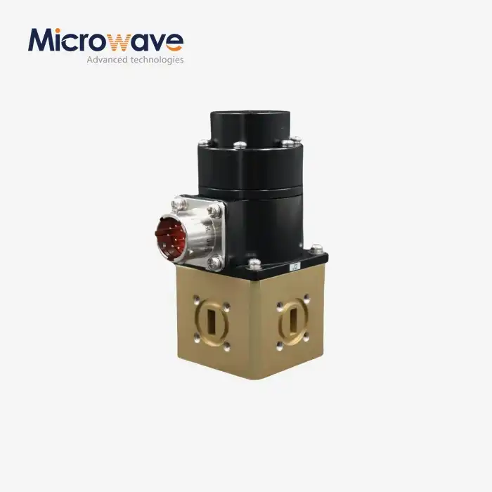
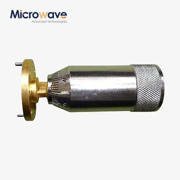
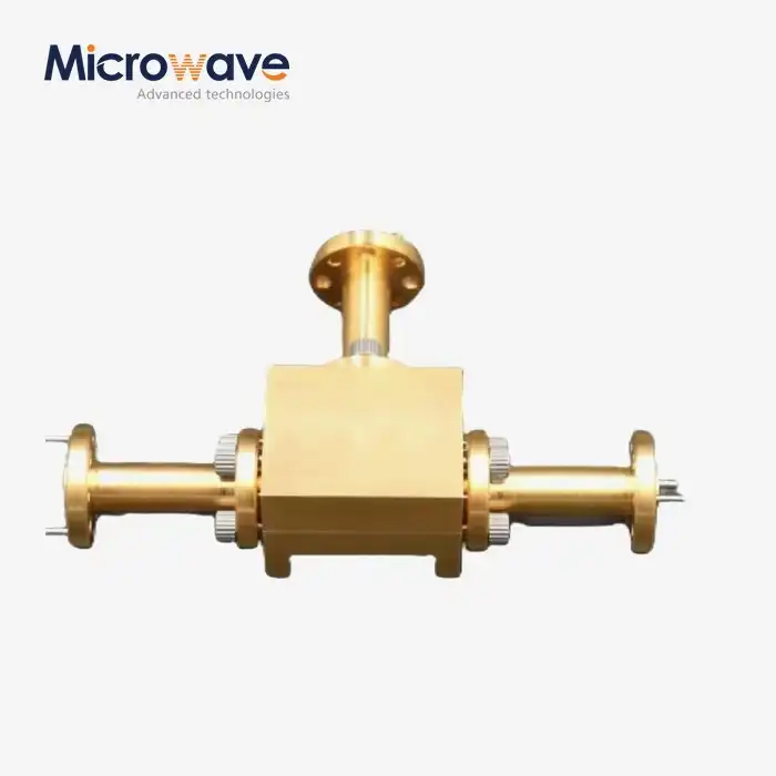
A well-engineered variable waveguide attenuator can handle 100W continuous wave (CW) power without significant drift, provided it is built with appropriate materials, thermal management features, and precision mechanical design. The air-dielectric nature of waveguide transmission lines gives these components a natural advantage over coaxial alternatives in high-power environments. That said, performance stability at this power level is not automatic. It depends on construction quality, operating frequency band, and installation conditions. Understanding what drives drift — and how to prevent it — is essential for any procurement engineer sourcing these components for radar, satellite ground stations, or defense systems.
Understanding Variable Waveguide Attenuators and Their Power Handling Limits
What Defines a Variable Waveguide Attenuator
An accurate microwave part called a variable waveguide attenuator changes the signal strength in a waveguide transmission line by adding a resistive gear or spinning an absorptive element into the electromagnetic field. Unlike a fixed attenuator, it lets you change the level continuously or in steps, usually from 0 dB to 30 dB or higher, without stopping the signal path. This means it can be used in situations that need to control gain in real time, protect the receiver, and calibrate the radar across bands from X-band to W-band.
Key Specifications That Affect Power Handling
Several electrical and physical factors directly show if a unit can handle 100W CW without losing its performance. This is the most important list of core specs:
- Attenuation range and accuracy: High-precision rotary vane models typically achieve ±0.1 dB accuracy, supporting reliable power control at high input levels.
- Insertion loss: Residual loss at 0 dB setting is often below 0.5 dB, preserving system efficiency even at full power.
- VSWR: A low VSWR — typically under 1.15:1 — minimizes reflections that could stress the upstream source at 100W.
- Power rating: Waveguide variants handle kilowatts of peak power in pulsed systems and meaningful average CW power due to the absence of a center conductor and superior thermal mass.
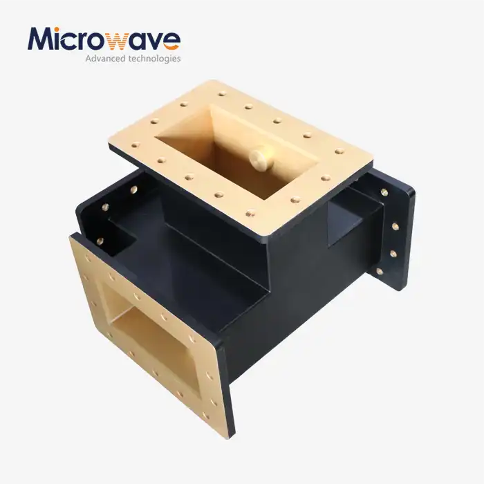
The materials used for the resistive rotor and frame are very important for keeping the temperature stable. Surfaces that are gold- or silver-plated on the inside reduce resistance losses and slow surface oxidation, which is a frequent reason why insertion loss degradation happens over time. High-quality metal or brass housings give the structure the rigidity it needs to keep the mechanical balance when the temperature changes. For uses that follow MIL-DTL-3933, it's also important to check for environmental robustness, which includes vibration and extreme temperature changes.
Material Choice and Construction Quality
The resistive vane and housing materials play a major role in thermal stability. Gold-plated or silver-plated interior surfaces reduce resistive losses and slow surface oxidation, which is a common cause of long-term insertion loss degradation. Housings machined from high-grade aluminum or brass provide the structural rigidity needed to maintain mechanical alignment under thermal cycling. For applications governed by MIL-DTL-3933, environmental robustness — including vibration and temperature extremes — must also be verified.
Technical Analysis: Can Variable Waveguide Attenuators Sustain 100W CW Without Drift?
Thermal Expansion and Its Effect on Attenuation
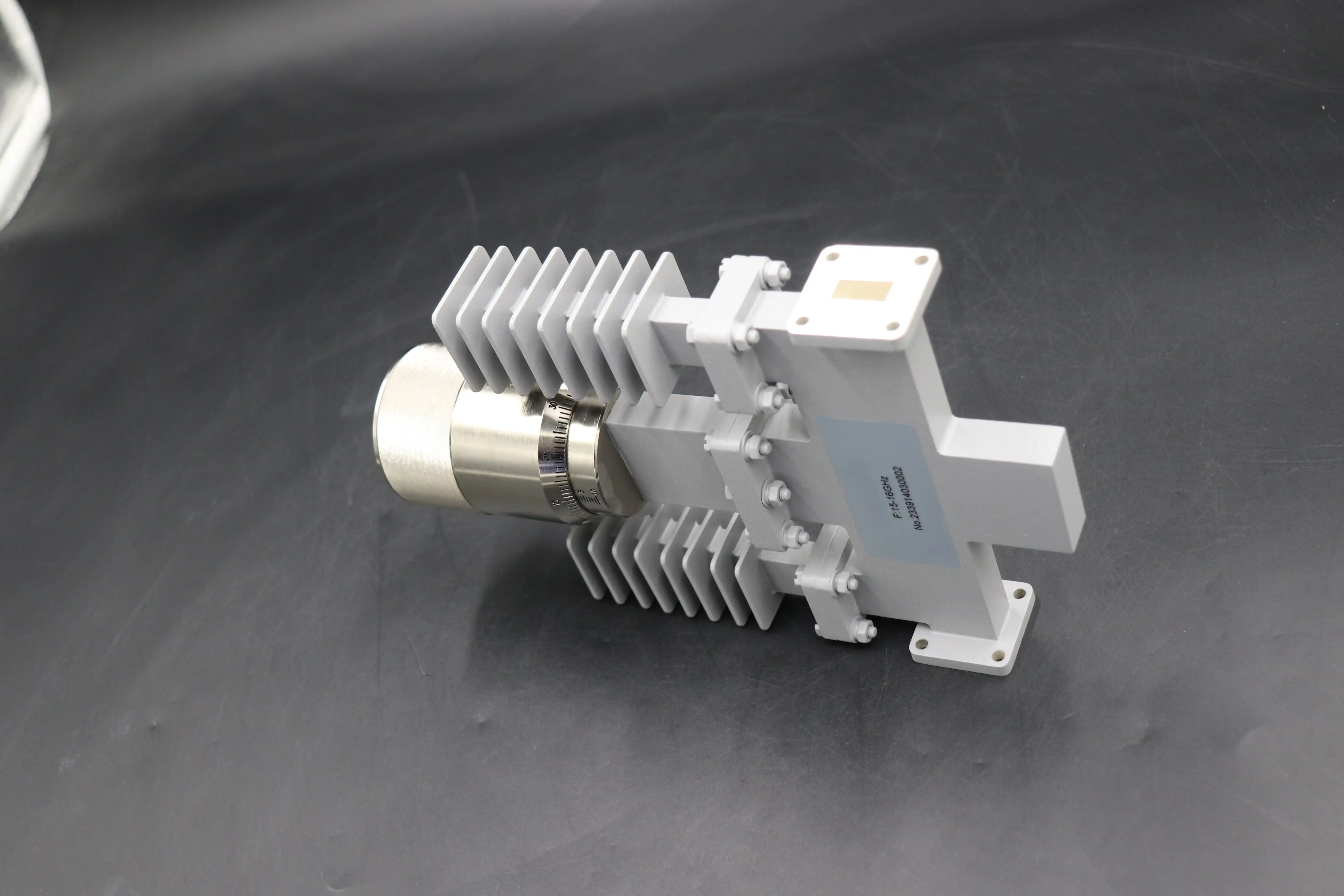
At 100W CW, the resistive vane and the metal structure around it get hot. This leads to thermal expansion, which can move the vane relative to the waveguide field and cause changes that can be measured in attenuation. This is called thermal drift. Even a 0.2 dB change in attenuation at full power can make measurements less accurate in precision test environments. Designs with heat-sink features or metals that don't change much in temperature lessen this effect by a large amount.
How Design Innovations Address Drift
Leading manufacturers deal with drift in a number of tried-and-true engineering ways. Copper-based resistive elements move heat away from the vane more quickly than other types of materials. Better internal airflow and fewer hot spots are caused by optimized waveguide shape. Even when the temperature changes, precision mechanical drives, like micrometer-driven types, keep their positions stable. For automated test equipment (ATE) setups, motorized versions with stepper motors and GPIB or USB interfaces make it possible to script attenuation sweeps and reduce the amount of manual handling that could cause mechanical hysteresis.
Real-World Performance Boundaries
Published information from well-known companies that make microwave parts shows that variable waveguide attenuators in the WR-90 (X-band) and WR-28 (Ka-band) configurations can regularly handle CW power levels well above 100W when they are placed correctly. Peak power needs for pulsed radar uses are in the kilowatt range. This is where the air-dielectric waveguide construction really shines. It's not always the part itself that acts as the actual limit. Often, it's the thermal contact between the attenuator body and the system frame.
Comparing Variable Waveguide Attenuators with Other Attenuator Types for High-Power Applications
Waveguide vs. Coaxial Attenuators
Coaxial attenuators are small and cheap, but they have a middle wire and a dielectric material that make it hard for them to handle high voltages and heat. A lot of coaxial designs reach their rated thermal limits at 100W CW, which makes it more likely that the dielectric will break down and the performance will change. Waveguide attenuators can handle the same amount of power with less insertion loss and better thermal stability because they are made of metal and air. The waveguide method is the usual choice for military and satellite procurement teams when building systems that work above 10 GHz.
Adjustable vs. Fixed Waveguide Attenuators
Fixed waveguide attenuators are the most stable because they don't have any moving parts that could move when heated or stressed mechanically or thermally. But once they are installed, they don't give you any options. When you make an adjustable type, you have to be more careful with the production tolerances of the vane or spinning system so that it works the same way every time at high power. It's clear what the trade-off is: fixed types work best for static, highly stable links, while adjustable types work best for test benches, calibration systems, and other places where signal level management is built into the way the system works.
Resistive Attenuators in High-Power Scenarios
Lossy ceramics or materials filled with carbon are used in resistive attenuators for waveguide systems to soak up energy. Even though they have a simple structure, how much power they can lose depends on how well the material conducts heat and how well it is mounted. Resistive types may have more attenuation drift than rotary vane types because the material that absorbs heat doesn't heat up evenly. For precise tasks using more than 50W CW, spinning vane or flap-type designs that control heat well are still the best choice.
Procurement Guide for High-Power Variable Waveguide Attenuators
Evaluation Criteria for 100W CW Applications
Before putting in an order for high-power CW environments, buyers should make sure of the following. The average rated power of the part must be higher than the CW demand of your system by at least 20%. Your waveguide size (WR-90 for X-band, WR-28 for Ka-band, etc.) must match the frequency band it works with. If you want to be sure of the insertion loss at the working frequency, you should look at test data from the maker instead of guessing it from a nominal spec sheet.
OEM Customization and Lead Time Considerations
A lot of uses are covered by standard catalog models, but OEM customization takes care of the odd ones, like frequency bands that aren't common, flange types that aren't standard, powered drive needs, or extended temperature range requirements. ADM provides OEM services that include rapid prototyping, which lets engineers test a custom design before it is made on a large scale. Custom waveguide systems have different lead times depending on how complicated they are, so working with the supplier's expert team early on lowers the risk of the purchase. Aligning production schedules and talking about volume pricing are helpful for bulk sales.
Total Cost of Ownership
When buying something, choices based only on unit price often don't take into account long-term costs. A part with better temperature stability and low drift might cost more at first, but it lowers the number of times it needs to be calibrated, the time it needs to be serviced, and the cost of replacing it. A good total cost analysis starts with looking at things like durability, technical support after the sale, and certification paperwork, such as ISO 9001 and RoHS compliance.
Best Practices for Maintaining Stable Performance at 100W CW
Installation and Thermal Management
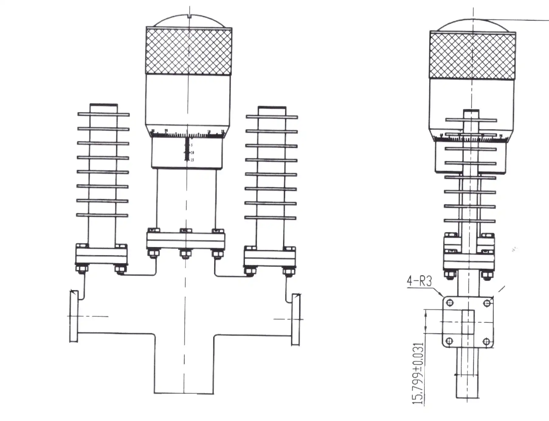
Correct placement has a direct effect on how drift behaves. To help heat move away from the blade assembly, the variable waveguide attenuator in the body should be attached to a frame surface that is good at conducting heat. Waveguide plates need to be clean, flat, and torqued to the right level. Any gap or mismatch causes VSWR problems that get worse when the temperature changes. When the temperature outside is high, you might need forced-air cooling or heat sink attachments.
Environmental and Mechanical Considerations
In the field, temperature changes and mechanical shaking are the two most common things that put waveguide attenuators under stress. Defense and aerospace platforms put parts through both at the same time. Units built to MIL-DTL-3933 or similar environmental standards make sure that the mechanical drive and resistive element stay stable over the required temperature range. The adjustment drive has locking mechanisms that are resistant to vibrations that stop position drift caused by resonance.
Routine Calibration and Monitoring
Engineers can find changes in insertion loss before they affect system performance by checking the system on a regular basis with a vector network analyzer (VNA). If the loss changes by more than 0.3 dB from the baseline calibration, it's likely that the vane is dirty, the surface is oxidized, or there is mechanical wear. Also, make sure that mechanical drives move smoothly and consistently. If the drive thread is stiff or has backlash, it could cause mistakes in position-dependent attenuation under load.
Conclusion
When the right materials, mechanical precision, and temperature design are used to build a variable waveguide attenuator, it can handle 100W CW without any noticeable shift. The main factors are the type of material used, the shape of the waveguide, and how it is installed. It is important for procurement teams working in military, satellite communications, or industrial test systems to choose a unit with proven power ratings, low insertion loss, and the right certifications, and then make sure it is installed properly so it works well for a long time. When standard catalog models don't work, OEM customization is the way to get a perfect fit.
FAQ
What frequency ranges do high-power waveguide attenuators cover?
By design, variable waveguide attenuators are band-specific. The frequency range that can be used is based on the size of the waveguide. For example, the WR-90 covers the X-band (8.2–12.4 GHz), the WR-28 covers the Ka-band (26.5–40 GHz), and the WR-10 covers the W-band (75–110 GHz). ADM has products that cover all of these common bands and have low VSWR.
What causes thermal drift in a waveguide attenuator under CW power?
Thermal drift happens when power stays on for a long time and heats the resistive vane and case. This changes the dimensions of the vane and moves it in the waveguide field. This may change the VSWR and change the effective reduction. Drift stays within acceptable ranges with good thermal management, which includes using conductive mounts and materials that don't change temperature easily.
What is the difference between direct-reading and micrometer-driven models?
Direct-reading types show attenuation on a calibrated drum scale so that changes can be made quickly and again and again. Micrometer-driven models have better mechanical detail, but you need a calibration guide to figure out how to change the drive position to a reduction in decibels. For lab work that needs to be very precise, micrometer-driven designs are best.
Are motorized waveguide attenuators available for ATE systems?
Yes, there are motorized types with stepper drives and standard transmission interfaces like GPIB, USB, and Ethernet that can be used to set up automated test tools. As usual in radar cross-section testing and satellite link simulation, they allow remote attenuation sweeps that are controlled by scripts.
Can a standard catalog model handle all 100W CW applications?
Not all the time. Standard models can meet most needs, but if you have a unique flange configuration, a wide temperature range, or a frequency band that isn't standard, you may need a custom design. To quickly handle these situations, ADM offers OEM design with prototyping help.
Source Your Variable Waveguide Attenuator from ADM
Advanced Microwave Technologies Co., Ltd. (ADM) is a company that has been making and selling variable waveguide attenuators for more than 20 years and is ISO 9001 certified. From the first proposal to delivery of the prototype and full-scale production, our team helps businesses buy things. When it comes to high-power CW applications in the defense, satellite, and industrial test markets, we offer OEM customization, quick turnaround, and strict quality control. To get a price or view product datasheets, you can email our engineering team at craig@admicrowave.com.
References
1. Pozar, D. M. — Microwave Engineering, 4th Edition. Wiley, 2011.
2. Montgomery, C. G., Dicke, R. H., & Purcell, E. M. — Principles of Microwave Circuits. MIT Radiation Laboratory Series, Vol. 8. McGraw-Hill, 1948.
3. IEEE Transactions on Microwave Theory and Techniques — Thermal Effects on Waveguide Component Performance in High-Power CW Systems. IEEE, 2018.
4. Collin, R. E. — Foundations for Microwave Engineering, 2nd Edition. IEEE Press / Wiley-Interscience, 2001.
5. MIL-DTL-3933 — Detail Specification: Attenuators, Fixed and Variable, Radio Frequency. U.S. Department of Defense, 2005.
6. Microwave Journal — Power Handling and Thermal Management in Precision Waveguide Assemblies. Microwave Journal, 2020.