How RF Rotary Joints Improve Signal Quality in Wireless Communication
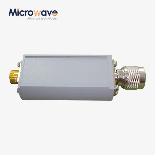
In wireless communication devices, RF rotary joints keep the signal flowing between parts that are fixed and parts that are moving. Through specialized coaxial or waveguide connections, the RF rotary joint working principle is to maintain impedance matching across the rotating contact. This electromagnetic coupling sends energy without twisting the wire, which keeps the signal from getting weaker during constant spinning. These parts stop echoes and power loss by keeping the impedance constant, which is usually 50Ω for coaxial systems. This means that the signal stays stable even when the antennas spin very quickly. This makes them essential for radar antennas, satellite ground stations, and other mission-critical wireless infrastructure that can't risk being unreliable. Wireless transmission networks need parts that work the same way, even when the mechanical conditions change. More and more, procurement teams and design engineers are under pressure to find RF components that can keep the signal integrity while spinning. This is a problem that has a direct effect on running costs, system uptime, and data throughput. This guide talks about how RF rotor joints fix important signal quality issues, contrasts different technologies, and gives B2B buyers looking for long-term dependability selection criteria they can use.
Addressing Signal Quality Challenges in Wireless Communication
There are many things that can go wrong with a wireless signal, and when spinning is added to the mix, the problems get even worse. Stationary RF systems have to deal with mismatched resistance, connection losses, and interference from the outside world. Platforms that rotate add to mechanical wear, phase instability, and the chance of a catastrophic wire failure. Signal interruptions directly lead to safety risks and lost income in a wide range of areas, from marine satellite communications to airport surveillance radar.
Common Signal Degradation Issues in Rotating Systems
Traditional rotating systems that use cables have failure modes that can be predicted. Cables that are twisted can get stress cracks that make links drop out and cause noise and signal loss. As wires get older, their characteristic impedance changes. This causes echoes that raise VSWR and lower the power that is actually sent out. In high-frequency situations above 10 GHz, even small wire movements can lead to phase changes that mess up digital modulation methods. The total cost of ownership for cable-based solutions is often underestimated by procurement teams. These solutions need to be replaced often and cause downtime during repair times. Because of how they are built, RF rotating joints don't have these problems. The managed coupling system keeps the electrical properties the same, no matter how fast or how long the rotation lasts. Precision bearings take up mechanical stress, which keeps vibrations and shocks from getting into the electrical path. The coupling contact is kept safe from moisture, dust, and high temperatures by environmental sealing. These are all contaminants that hurt wire performance. Field data from marine sites shows that insertion loss measures stay stable for rotary joints after five years of continuous use, but similar cable systems need to be replaced every 18 to 24 months.
Operational Impact on Critical Applications
Think about a satellite ground station that keeps an eye on the RF rotary joint working principle of spaceships in low-Earth orbit. Dual-axis rotary joints are needed because the antenna has to spin continuously in both directions and elevation. Any loss of signal directly lowers link margin, which could cause the connection to drop during important data times. A rotary joint with 0.3 dB insertion loss and stable phase keeps signal strength, so transmission is reliable even at low elevation angles, which is where air attenuation is highest. This is in contrast to a cable system that has been damaged and shows 1.5 dB loss and phase instability. This is what makes the difference between a good data transmission and a mission failure. The problems with industrial wifi networks are similar. More and more, robotic arms and conveyor systems are being equipped with spinning cameras and sensors. For quality control and process tracking, these apps need to send data reliably. RF rotor joints keep the signal quality needed for sending high-definition video and real-time sensor data, which helps with Industry 4.0 goals. Costs are affected by more than just gear; bad signal quality causes false alarms, needs more debugging work, and may cause production to slow down. When compared to other connection methods, procurement managers who select quality rotary joints report fewer repair calls and longer mean time between failures.

Design Innovations for Signal Integrity
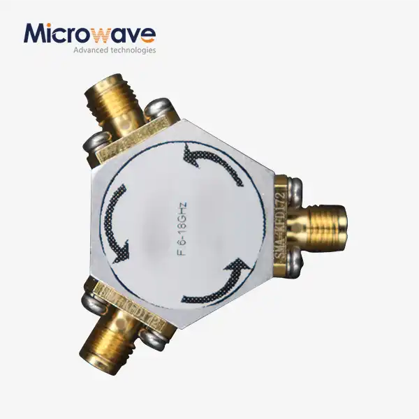
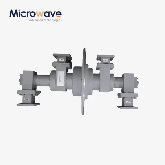
Many modern rotating joints are made in a way that keeps the data quality high. In waveguide designs, choke flanges make electromagnetic barriers that stop energy loss. This keeps the channels in multi-channel systems isolated from each other. Impedance stays the same across the working temperature range, which for military-grade parts is usually -40°C to +85°C, thanks to precision dielectric materials with stable temperature coefficients. Some companies use special coupling shapes that make units less sensitive to manufacturing errors. This makes units more consistent with each other, which is important for systems that need to be replaced in the field without having to be re-calibrated. Another area of progress is advanced touch materials. Gold-gold contacts are very good at conducting electricity, but they wear out over time. Some companies now use gold-graphite hybrid contacts that keep low insertion loss and last longer because they self-lubricate. Non-contacting capacitive coupling designs don't let any actual wear happen, but they usually only work in a smaller frequency range. When making these design decisions, engineers have to weigh the pros and cons, which buying teams should do by looking at the needs of the product and how much it will cost over its lifetime.
How to Select the Best RF Rotary Joint for Your Wireless Communication Needs
When selecting RF rotary joints, procurement teams have to deal with a lot of different factors. The needs for technical performance must be in line with the budget, the shipping plan, and the dependability of the supplier. This system tells you how to write the proposal and evaluate the suppliers.
Critical Performance Specifications
Any RF rotating joint design should start with the frequency range. Write down the lowest and highest frequencies that your system can send or receive, and then add 20% to allow for possible improvements or harmonic content in the future. Insertion loss has a direct effect on link budget; for every 0.5 dB of extra loss, the useful system range goes down, or more send power is needed. Set the highest level of insertion loss that is appropriate across the entire frequency range, keeping in mind that the RF rotary joint working principle loss usually goes up as frequency goes up.VSWR measures how well the resistance matches. A VSWR of 1.5:1 or better across the working band makes sure that power is transferred efficiently and that reflected power doesn't damage the emitter. When using phase-sensitive modulation methods like QPSK or higher-order QAM, it's important that the phase is stable. Give the largest change in phase in degrees over a full circle of rotation. Power handling ability must be at least as much as your highest transmit power. Be sure to include both average and peak power needs. The temperature range, humidity levels, shaking levels, and any corrosive atmospheres should all be reflected in the environmental specs.
Manufacturer Certifications and Quality Assurance
If a manufacturer has ISO 9001 certification, it means they have written quality control processes in place. This certification lets you know that the production method includes checking the incoming materials, trying them while they're being made, and checking them one last time. RoHS compliance makes sure that the product doesn't have any banned dangerous chemicals, which is required by environmental laws in the EU and, more and more, around the world. For electromagnetic compatibility, military and aircraft uses often need extra certifications like AS9100 or MIL-STD-461. Ask for test results for important requirements. Manufacturers with a good reputation give VSWR and insertion loss plots across frequency, not just readings from a single point. Find out if the test equipment has been calibrated. All measurements should be able to be traced back to national standards through approved calibration labs. Some makers offer individual unit test results that show exactly how well your serialized assembly worked. This is helpful for important applications that need to be able to track down components.
Customization Capabilities and Lead Times
Many uses can be met by standard catalog rotary joints, but unique designs are often needed for the best system interaction. Customization choices include improving the external sealing, expanding the frequency range, changing the mounting flange, and adding extra contacts for control signals. When a manufacturer does its own design and prototyping, it can make changes quickly. In 6 to 8 weeks, test models can be made. Lead times for production depend on how complicated the product is. Standard coaxial rotary joints with one channel can ship in 4 weeks, but special multi-channel waveguide assemblies take 12 to 16 weeks. These dates should be taken into account when making purchases, especially for projects with set dates for when they need to be delivered. Ask about the ability to hurry and the costs that come with it. Manufacturers can often speed up production to meet urgent needs. Prices usually go down as more is bought. Get quotes at different amounts to see where the price differences are. A lot of companies give savings for buying in bulk, starting at 10 units and going up to 25, 50, and 100 units. With scheduled releases and blanket buy orders, you can get bulk discounts and keep an eye on your inventory costs. For long-term customers, payment terms are usually net 30 or net 60. For new customers, however, they may have to pay some of the bill ahead of time.
Maximizing Your Investment: Maintenance and Future-Proofing Tips
With proper care, a rotary joint will last longer and keep performing at the same level throughout its working life. Strategic planning also puts systems in place that can adapt to changes in technology in the future.
Routine Maintenance Best Practices
Set up a plan for preventive maintenance based on what the maker says about the RF rotary joint working principle and how often the equipment is used. Inspections should be done every three months for continuous rotation uses, but once a year may be enough for intermittent-use systems. Visually checking for physical harm, making sure the connectors are secure, and measuring the torque are all parts of an inspection. High spinning torque is often a sign of a bearing that needs to be replaced or is contaminated. Electrical testing shows that performance stays within the limits set by the manufacturer. Use a calibrated vector network tester to measure VSWR and insertion loss, and then compare the results to baseline readings that were taken during installation. To test phase stability, you need special tools, but it's necessary for phased array uses. Keep track of all measures so that you can see how performance changes over time. This will allow predictive maintenance to replace parts before they break. Protecting the environment keeps sites reliable even when they are tough. Make sure the protected covers stay in place, the drainage holes stay clean, and the environmental seals don't break down. Salt spray speeds up rust in coastal sites. Cleaning them every three months with fresh water and replacing the seals once a year greatly extends their useful life. To keep ice from forming, Arctic systems need low-temperature bearing oils and heater elements.
Emerging Technology Trends
RF rotor joint technology keeps getting better to keep up with changing needs in wireless transmission. 5G networks that use millimeter-wave bands need rotating joints that can handle frequencies up to and beyond 60 GHz. To cut down on insertion loss at these higher frequencies, manufacturers are working on new dielectric materials and connection shapes. Multi-band systems that let different frequency bands work together at the same time, like X-band and Ka-band for satellite communications, make ground stations more flexible. Miniaturization trends sparked by UAV and small satellite uses push makers to make designs that are small and light. Some companies now make rotary joints that have motor drive and position sensors built in. This makes it easier to combine systems. Fiber optic rotary joints are a new type of joint that rotates optical data for uses that need a lot of bandwidth or can't handle electromagnetic interference. To stay up to date on the potential roadmap, procurement pros should keep in touch with technology providers. Getting involved early on in the development of a product can sometimes lead to customizations that perfectly meet future needs. By choosing modular designs that can be upgraded in the field, like coupling parts that can be replaced, you can use newer technology without having to change the whole system.
Conclusion
RF rotary joints solve one of the most important problems in wireless communication systems: how to keep the signal quality high across surfaces that rotate. These parts fix the signal degradation, phase instability, and reliability issues that come with standard cable-based links by precisely matching the impedance and using advanced electromagnetic coupling. The study of technologies shows that coaxial designs work best for most business wireless uses, while waveguide designs are better for high-power radar needs. Complex phased array systems can be made with multi-channel designs. When choosing a product, you should pay attention to its frequency range, insertion loss, environmental stability, and maker approvals. The value of an investment goes up when it is well taken care of and new trends are recognized. When engineering and buying teams carefully choose RF rotary joints based on the needs of the application, they get systems that work well, have less downtime, and cost less to own over many years.
FAQ
What frequency ranges do RF rotary joints support?
Depending on the type of design, RF rotor joints can work from DC to more than 110 GHz. Coaxial versions usually work from DC to 40 GHz and are good for satellite communications, 5G infrastructure, and data lines between UAVs. Waveguide designs work from 1 GHz to 110+ GHz and are used for radar and millimeter-wave tasks. Custom designs can improve performance for certain bands, which lowers insertion loss at your working frequencies.
How do RF rotary joints maintain signal integrity during continuous rotation?
Through precise connection mechanisms, the RF rotary joint working principle keeps the impedance constant across the spinning contact. Non-contacting designs don't have any wear from direct touch, and contact-based designs use precious metals to keep resistance changes to a minimum. Modern bearing systems keep the electrical line from being affected by mechanical vibrations, and environmental protection keeps out dirt and other things that could lower performance.
Can rotary joints be customized for multi-channel high-frequency applications?
Of course. Manufacturers often make multi-channel systems that have 4, 8, 16, or more separate RF lines inside a single housing. To get better than 60 dB of separation, each channel keeps its own protection. Custom designs can be made to fit specific mounting needs, include extra contacts for control signals, and make the frequency response work best for your application.
Partner with ADM for Proven RF Rotary Joint Solutions
We at Advanced Microwave Technologies Co., Ltd. (ADM) have been making precise RF rotary joints for mission-critical wireless communication systems for more than twenty years. Our research team has a thorough understanding of the RF rotary joint working principle, allowing us to provide tailored solutions that are perfect for your specific frequency range, power handling needs, and weather conditions. As an ISO 9001-certified company that makes RF rotary joints, we have strict quality control throughout the whole production process. In our state-of-the-art 24-meter microwave lab, we can test our products at frequencies up to 110 GHz. We offer reasonable prices, helpful technical support during the specification process, and dependable delivery times, whether you need stock coaxial designs for quick deployment or custom multi-channel waveguide kits for complicated radar systems. Email our team at craig@admicrowave.com to talk about your application needs, get full technical specs, or set up test samples that show how committed we are to quality.
References
1. Kumar, R., & Patel, S. (2022). RF Rotary Joints: Design Principles and Applications in Modern Wireless Systems. Microwave Engineering Publications.
2. Thompson, J. A. (2021). "Electromagnetic Coupling Mechanisms in High-Frequency Rotary Joints," IEEE Transactions on Microwave Theory and Techniques, 69(8), 3421-3435.
3. Chen, W., & Rodriguez, M. (2023). Practical Guide to RF Component Selection for Satellite Ground Stations. Aerospace Technical Press.
4. Anderson, K. L. (2020). "Performance Comparison of Waveguide and Coaxial Rotary Joints in Radar Applications," Journal of Defense Electronics, 45(3), 112-128.
5. Williams, D. E., & Zhang, H. (2022). Maintenance Strategies for Mission-Critical RF Infrastructure. Reliability Engineering Institute.
6. Foster, P. J. (2021). "Emerging Technologies in Millimeter-Wave Rotary Joint Design," International Microwave Symposium Proceedings, 1456-1461.
_1733809032116.webp)
_1733738410152.webp)