


What is a waveguide assembly?
Walk into any radar facility, satellite ground station, waveguide assembly, or aerospace testing lab, and you'll notice something interesting: massive antennas connected not by the thin coaxial cables you see behind your TV, but by robust metallic tubes and precisely engineered components. These are waveguide assemblies—the unsung champions of high-frequency signal transmission. When you're working with frequencies above 18 GHz, where coaxial cables simply can't handle the power or prevent signal loss, waveguide assemblies become absolutely essential. Over my two decades in the microwave industry at Advanced Microwave Technologies Co., Ltd, I've watched these components evolve from simple hollow tubes into sophisticated systems that power everything from weather monitoring satellites to defense radar arrays. This article breaks down exactly what waveguide assemblies are, why they matter, and how they solve critical engineering challenges that modern technology demands.
What is a Waveguide Assembly? The Core Definition
What is a waveguide assembly? A waveguide assembly is a specialized high-frequency transmission system consisting of hollow metallic structures—typically crafted from copper, aluminum, or brass—that guide electromagnetic waves through controlled reflection with minimal signal loss. Unlike coaxial cables that use a center conductor surrounded by insulation, waveguide assemblies rely on the physical dimensions of the hollow channel itself to propagate microwave and millimeter-wave signals. These assemblies operate primarily in TE (Transverse Electric) or TM (Transverse Magnetic) modes, with TE10 being the most commonly used mode because it offers the lowest cut-off frequency.A complete waveguide assembly typically includes multiple precision-machined components: rigid straight sections that form the main transmission path, mitered bends for directional changes (usually at 45 or 90 degrees), twists for polarization manipulation, and precisely manufactured flanges that connect sections together. The flanges—such as CPR (Cover-Plain-Rectangular), UG (Universal General), or UBR (Unflanged-Boss-Rectangular) standards—must align perfectly to prevent RF leakage and maintain signal integrity. The interior dimensions are engineered to exact tolerances; a WR-90 waveguide, commonly used in X-band applications, has internal dimensions of approximately 0.9 inches by 0.4 inches, and even micron-level deviations can cause performance issues at higher frequencies.
The Problem It Solves: Why Waveguide Assemblies Exist
The fundamental challenge in high-frequency signal transmission is simple yet critical: as frequency increases, traditional coaxial cables become inefficient, lossy, and unreliable. At frequencies above 18 GHz—and especially beyond 40 GHz—coaxial cables suffer from excessive attenuation, where signal strength diminishes rapidly over short distances. This loss translates directly into wasted power, reduced range, and degraded system performance. The skin effect, where alternating current tends to flow near the conductor's surface rather than through its core, intensifies dramatically at microwave frequencies, creating heat and further signal degradation. Waveguide assemblies solve this problem through a fundamentally different approach to wave propagation. The hollow metallic structure confines electromagnetic energy through boundary conditions rather than through a center conductor. This design reduces resistive losses because the currents flow only along the interior walls, which have much larger surface areas than a thin coaxial center conductor. The result? Insertion loss in a quality waveguide assembly might be as low as 0.03 dB per meter at X-band frequencies, compared to several dB per meter for even the best coaxial cable at the same frequency. Power handling capability presents another critical advantage. Satellite uplink transmitters and high-power radar systems often operate at kilowatt power levels. Coaxial cables at these power levels risk dielectric breakdown—where the insulating material between the center conductor and shield fails catastrophically. Waveguide assemblies, filled only with waveguide assembly air or inert gas, can handle peak powers exceeding 100 kilowatts without breakdown concerns. This makes them indispensable in military applications where jamming systems and electronic warfare equipment demand both high power and reliability under extreme conditions. Environmental resilience matters enormously in mission-critical applications. Aerospace and shipboard systems face temperature extremes, vibration, humidity, and salt spray. Waveguide assemblies constructed with proper materials and protective coatings maintain electrical performance across temperature ranges from -55°C to +125°C. When properly pressurized with dry nitrogen, they resist moisture ingress that would otherwise cause corrosion and signal degradation over years of operation.
Core Features & Functionality: What Makes Waveguide Assemblies Work
The engineering sophistication of modern waveguide assemblies extends far beyond simple hollow tubes. Understanding their core features reveals why they remain the gold standard for high-frequency applications.
Precision Manufacturing and Dimensional Control
Every waveguide assembly begins with exacting mechanical tolerances. The internal dimensions determine the cut-off frequency—below which signals cannot propagate—and must be maintained to within 0.001 inches across the entire assembly length. Manufacturing techniques include CNC machining for rigid sections, electroforming for complex shapes, and precision stamping for high-volume production. Surface finish matters tremendously; roughness increases resistive losses, so interiors are typically electroplated with silver or gold to minimize skin effect losses and prevent oxidation.

Component Integration and System Design
A functional waveguide assembly rarely consists of a single straight section. Real-world installations require directional changes, transitions between different waveguide sizes, and interfaces with other equipment. E-plane bends (where the electric field is parallel to the bend plane) and H-plane bends (where the magnetic field is parallel) each have distinct electrical characteristics. Mitered bends use precisely angled cuts to redirect signals with minimal reflection. Twist sections rotate the polarization plane, essential when connecting components with different orientations. Transitions—such as waveguide-to-coax adapters—allow interfacing with coaxial equipment while maintaining impedance matching to prevent signal reflections.
Flexible Waveguide Technology
Not every application allows rigid, fixed routing. Flexible waveguide assemblies use a convoluted metallic core—often constructed from interlocking helical strips—that permits bending while maintaining electrical performance. These assemblies come in two types: bendable-only versions that flex in E-plane and H-plane but cannot twist, and fully twistable versions that accommodate rotation around the longitudinal axis. Flexible assemblies prove invaluable in applications like rotating antenna pedestals, vibration-isolated equipment racks, and prototype systems where final routing remains uncertain. The tradeoff involves slightly higher insertion loss and lower power handling compared to rigid equivalents, but the mechanical advantages often outweigh these compromises.
Flange Standards and Connection Interfaces
The connection points between waveguide sections represent critical junctions where signal integrity can easily degrade. Industry-standard flanges ensure compatibility and proper alignment. Cover flanges feature a flat sealing surface, while choke flanges incorporate a quarter-wave channel that creates an RF short circuit, eliminating the need for gaskets in many applications. Bolt hole patterns and flange thickness follow strict standards such as MIL-DTL-3922 for military applications or EIA RS-261 for commercial use. Proper torque specifications during installation ensure both mechanical stability and electrical continuity.
Pressurization and Environmental Protection
Long waveguide runs—particularly those exposed to outdoor waveguide assembly environments—require pressurization to prevent moisture accumulation. Dry air or nitrogen at 2-5 PSI creates positive pressure that prevents humid air infiltration. Pressurization systems include gas inlets, pressure monitoring ports, and flexible sections that accommodate thermal expansion without losing seal integrity. Windows—thin dielectric barriers—seal waveguide ends while allowing signal transmission, useful when pressurized systems connect to non-pressurized equipment.
Technology Under the Hood: How Wave Propagation Works
The physics behind waveguide assemblies might seem abstract, but understanding the fundamentals clarifies why they perform so effectively. Electromagnetic waves traveling through a waveguide don't simply shoot straight down the tube like water through a pipe. Instead, they propagate through a complex pattern of reflections off the interior walls, creating standing wave patterns that determine which frequencies can successfully travel through the structure. The TE10 mode—the dominant mode in rectangular waveguides—features an electric field that varies sinusoidally across the width of the guide while remaining constant along the height. This field pattern reflects repeatedly between the side walls as it travels down the guide. The waveguide dimensions must exceed half the wavelength of the signal to support propagation; signals with wavelengths too long simply cannot establish the necessary field pattern and are rejected. Dispersion characteristics differ markedly from those of coaxial cables. In waveguides, phase velocity—the speed at which a point of constant phase travels—actually exceeds the speed of light, while group velocity—the speed at which signal information travels—remains below it. This peculiar behavior means that different frequency components within a signal travel at different velocities, creating pulse distortion in wideband applications. Engineers compensate through careful system design and equalization techniques. Mode purity—ensuring only the desired mode propagates—requires careful attention to mechanical discontinuities. Sharp corners, imperfect joints, or internal obstructions can excite higher-order modes that interfere with the primary signal. This explains why waveguide assembly manufacturing demands such extreme precision and why installation procedures emphasize cleanliness and careful alignment.
Key Advantages: Why Engineers Choose Waveguide Assemblies
The decision to specify waveguide assemblies over alternatives comes down to measurable performance advantages that directly impact system capability.
Lowest Insertion Loss at High Frequencies
Waveguide assemblies demonstrate insertion loss characteristics that improve relative to coaxial cables as frequency increases. At 10 GHz, quality coaxial cable might offer comparable or even better loss performance. By 40 GHz, waveguide assemblies typically show one-tenth the loss of coaxial equivalents over the same distance. This dramatic difference translates directly into extended range, reduced transmitter power requirements, and improved receiver sensitivity.
Exceptional Power Handling Capacity
Military and satellite applications routinely require power levels that would instantly destroy coaxial cables. A WR-90 waveguide assembly can safely handle continuous power levels exceeding 10 kilowatts and peak powers above 100 kilowatts, making it suitable for high-power radar transmitters, electronic countermeasures systems, and satellite uplink amplifiers. This capability eliminates the need for power dividers and combiners that would otherwise be required to split signals across multiple coaxial paths.
Long-Term Reliability and Stability
Properly manufactured and installed waveguide assemblies maintain electrical performance for decades. The absence of dielectric materials that can degrade over time, combined with corrosion-resistant plating, ensures stable insertion loss and VSWR throughout the system lifecycle. This reliability proves essential in applications like satellite ground stations that require 20-year service lives with minimal maintenance.
Electromagnetic Interference Immunity
The complete electromagnetic shielding provided by the metallic enclosure prevents both signal leakage and external interference. This characteristic becomes critical in dense RF environments where multiple transmitters and receivers operate in proximity, such as naval vessels or airport radar facilities. Waveguide assemblies maintain signal purity even when routing through electromagnetically noisy areas.
Potential Limitations & Considerations: Understanding the Tradeoffs
Waveguide assemblies offer unmatched performance at high frequencies, but they come with constraints that influence system design decisions.
Physical Size and Weight
Waveguide assemblies occupy significantly more space and weigh considerably more than coaxial equivalents. A WR-90 assembly weighs several pounds per meter, compared to ounces for coaxial cable. This becomes problematic in weight-sensitive aerospace applications or dense equipment installations where routing space is limited. Lower frequencies require larger waveguide dimensions; a Ka-band WR-28 waveguide is compact, while an L-band WR-650 waveguide becomes impractically large for many installations.
Installation Complexity and Cost
The precision required for waveguide installation exceeds that of coaxial systems. Flanges must align perfectly, bolt torque must follow specifications, and routing must avoid sharp bends that exceed minimum radius specifications. Installation typically requires skilled technicians familiar with RF practices. Material and manufacturing costs also exceed coaxial alternatives—a high-performance flexible waveguide assembly can cost hundreds or thousands of dollars per meter, compared to tens of dollars for quality coaxial cable.

Limited Flexibility in Routing
Rigid waveguide assemblies cannot accommodate the arbitrary routing possible with coaxial cable. Changes in direction require purpose-built bend sections, and the physical constraints of the waveguide assembly often dictate equipment layout rather than vice versa. Flexible waveguide assemblies address this limitation partially but introduce higher loss and reduced power handling.
Frequency Bandwidth Constraints
Each waveguide size operates effectively only across a limited frequency range—typically 1.5:1 bandwidth between the cut-off frequency and the onset of higher-order modes. Systems requiring multi-octave bandwidth may need multiple waveguide sizes or transitions, adding complexity. Coaxial systems offer much broader bandwidth in a single transmission line.
Waveguide Assemblies vs. The Competition: Comparative Analysis
Waveguide Assemblies vs. Coaxial Cables
The fundamental comparison in microwave transmission pits waveguide assemblies against coaxial cables. Below 10 GHz, coaxial cables often win on cost, size, flexibility, and ease of installation. Between 10-18 GHz, the choice depends on specific application requirements—short runs may favor coaxial, while longer distances or high power applications benefit from waveguide. Above 18 GHz, waveguide assemblies demonstrate clear superiority in insertion loss and power handling, despite their higher cost and installation complexity. The crossover point depends on system requirements; a satellite ground station designer accepts waveguide cost and complexity to achieve the performance necessary for reliable communication with a spacecraft 36,000 kilometers away.
Waveguide Assemblies vs. Substrate Integrated Waveguide (SIW)
Emerging substrate integrated waveguide technology creates waveguide-like structures within printed circuit board substrates using rows of metalized vias. SIW offers compact integration, low cost in volume production, and compatibility with planar circuit fabrication. Performance falls short of conventional waveguide assemblies—insertion loss runs higher, power handling is limited, and frequency range is constrained by practical PCB dimensions. SIW excels in millimeter-wave integrated circuits and consumer applications where cost dominates, while conventional waveguide assemblies remain superior for high-performance, high-power applications requiring maximum reliability.
Conclusion
Waveguide assemblies remain the foundation of high-frequency signal transmission, where performance cannot be compromised. Their unique combination of minimal loss, exceptional power handling, and long-term reliability makes them irreplaceable in aerospace, defense, satellite communications, and precision measurement applications. As wireless technology pushes into millimeter-wave frequencies for 5G and emerging 6G networks, the relevance of waveguide assemblies continues growing. Emerging manufacturing techniques—including additive metal printing and advanced plating processes—promise to reduce costs while maintaining the exacting performance standards these critical components demand. The future holds exciting possibilities for integration and miniaturization, but the fundamental physics ensuring waveguide superiority at high frequencies remains unchanged.
FAQ
Can I use a waveguide assembly designed for one frequency band at a different frequency?
A: Waveguide assemblies operate only within specific frequency ranges determined by their physical dimensions. Each waveguide size has a cut-off frequency below which signals cannot propagate, and an upper frequency limit beyond which higher-order modes appear and cause performance degradation. Using a waveguide outside its designated band results in either complete signal blocking (below cut-off) or unpredictable multi-mode propagation (above the single-mode range). The WR designation indicates the frequency range; for example, WR-90 operates from 8.2 to 12.4 GHz. Operating outside this range requires a different waveguide size.
What causes VSWR spikes in waveguide assemblies, and how do I troubleshoot them?
A: Voltage Standing Wave Ratio spikes indicate impedance discontinuities where signal reflections occur. Common causes include improperly mated flanges, where misalignment or contamination prevents proper electrical contact; damaged flange surfaces, dented waveguide sections, or internal obstructions like debris or moisture. Troubleshooting starts with visual inspection of all connections, verification of proper bolt torque, and checking for obvious damage. Time-domain reflectometry using a vector network analyzer can locate the physical position of discontinuities along the assembly, allowing targeted investigation. Cleaning flange surfaces, replacing damaged sections, and ensuring proper alignment typically resolve most issues.
How do I determine the minimum bend radius for flexible waveguide assemblies?
A: Manufacturers specify both static and dynamic minimum bend radius for flexible waveguide assemblies. Static radius applies to installations where the assembly remains in a fixed bent position, while dynamic radius—typically larger—applies when the assembly experiences repeated flexing. Exceeding these limits permanently damages the interlocking convolutions or corrugations, creating VSWR spikes and increasing insertion loss. The minimum radius correlates with waveguide size; smaller waveguides permit tighter bends. A WR-90 flexible assembly might specify a 75mm dynamic bend radius. Always consult the specific product datasheet, and when possible, use the largest practical bend radius to maximize service life and maintain optimal electrical performance.
Partner with ADM: Your Trusted Waveguide Assembly Manufacturer
Advanced Microwave Technologies Co., Ltd brings over 20 years of specialized experience as a waveguide assembly supplier serving defense contractors, satellite operators, waveguide assembly, and research institutions worldwide. Our ISO 9001:2015 certified manufacturing facility produces custom waveguide assemblies from 0.5 to 110 GHz, backed by our state-of-the-art 24-meter microwave darkroom for complete performance verification. Whether you need ruggedized military-grade assemblies, precision laboratory standards, or high-power satellite uplink components, our technical team collaborates with you from initial design through final testing. Contact craig@admicrowave.com today to discuss your waveguide assembly requirements and discover how our engineering expertise, quality control, and responsive service deliver the reliable solutions your mission-critical applications demand.
References
1. Pozar, David M. Microwave Engineering, Fourth Edition. John Wiley & Sons, 2011.
2. Balanis, Constantine A. Advanced Engineering Electromagnetics, Second Edition. John Wiley & Sons, 2012.
3. Rizzi, Peter A. Microwave Engineering: Passive Circuits. Prentice Hall, 1988.
4. Marcuvitz, Nathan. Waveguide Handbook. Institution of Engineering and Technology, 1986.
5. Saad, Theodore S. Microwave Engineers' Handbook, Volume 1. Artech House, 1971.
6. Montgomery, Carol G., Robert H. Dicke, and Edward M. Purcell. Principles of Microwave Circuits. Institution of Engineering and Technology, 1987.
YOU MAY LIKE
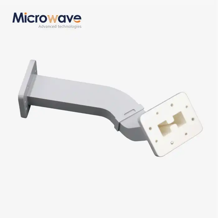 VIEW MOREDouble Ridge Waveguide Bend
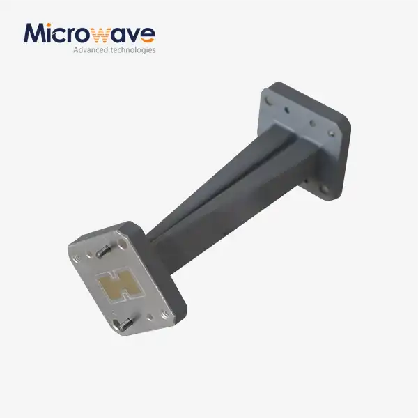 VIEW MOREDouble Ridge Twist Waveguide
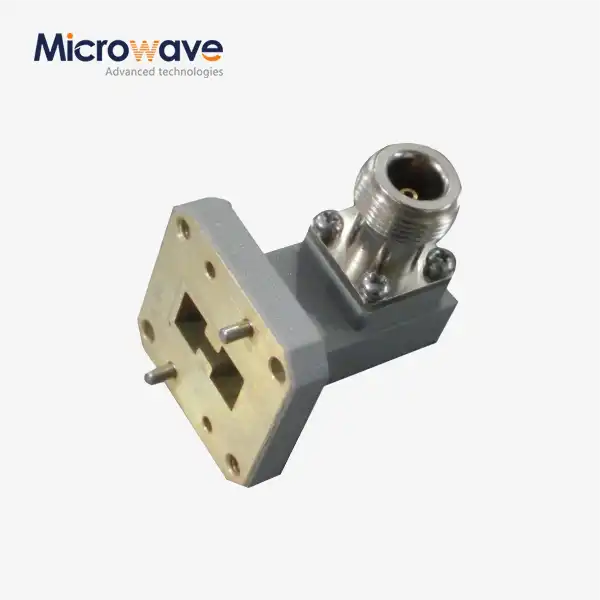 VIEW MOREDouble Ridged WG To Coaxial Adapter
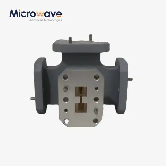 VIEW MOREDouble-Ridged Waveguide Magic Tee
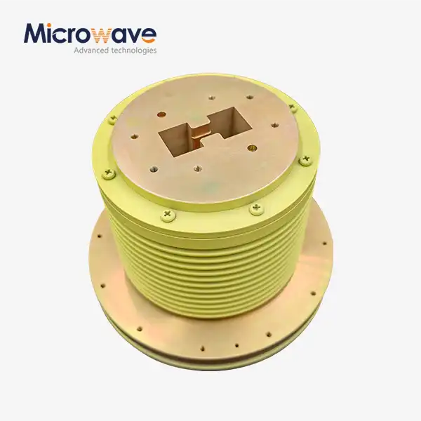 VIEW MOREDouble Ridge Waveguide Rotary Joint
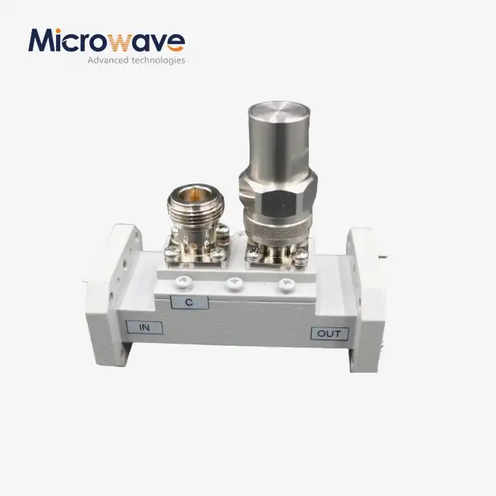 VIEW MOREDouble-Ridged Waveguide Loop Coupler
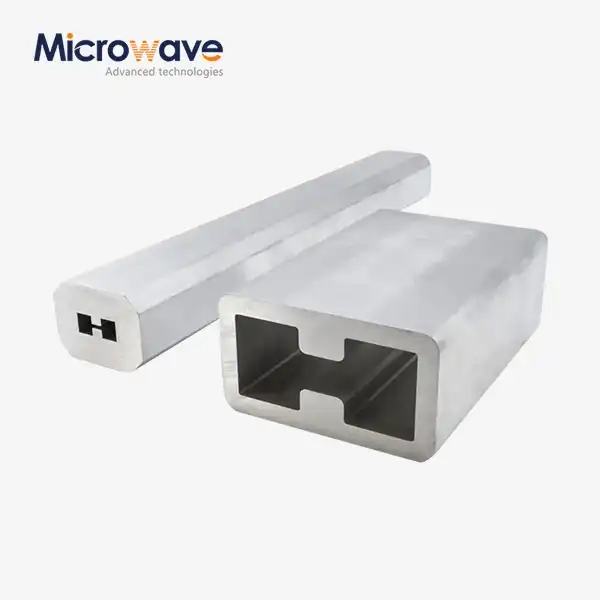 VIEW MOREDouble Ridge Waveguide Tube
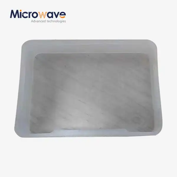 VIEW MOREPlastic Flange Caps
