How Resistive Card Position Tunes Variable Waveguide Attenuator Depth
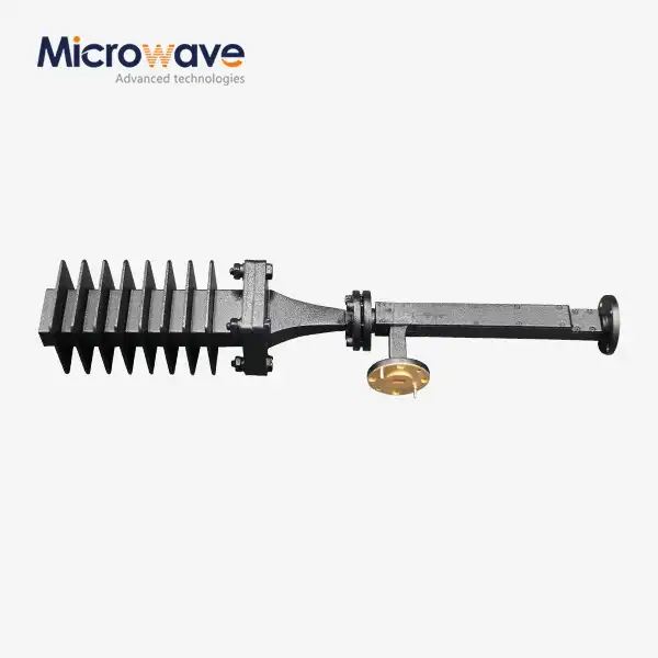
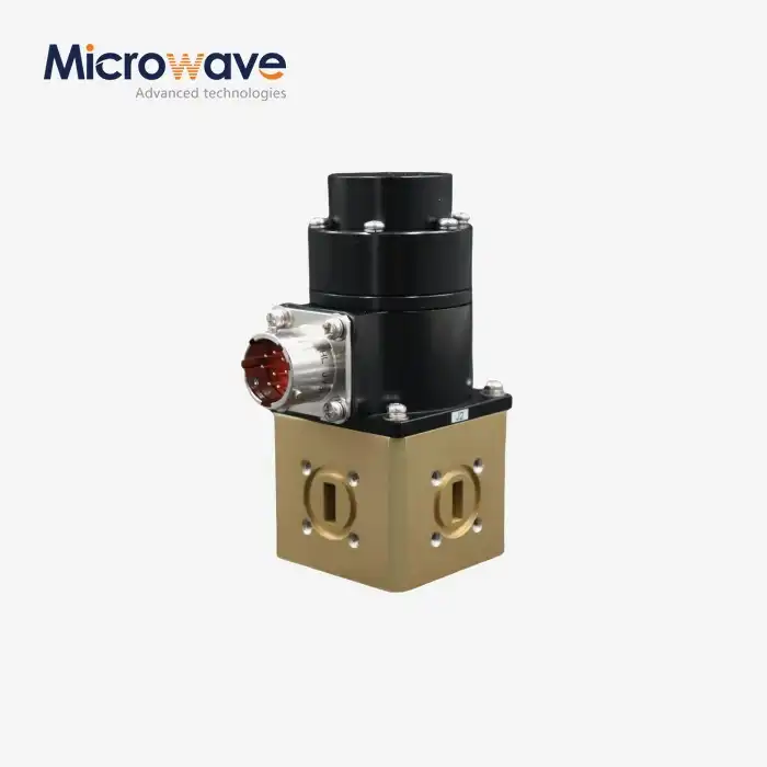
In variable waveguide attenuators, the resistive card position directly controls attenuation depth by modulating the interaction between the electromagnetic field and the resistive element. As the card moves deeper into the waveguide's electric field region, it absorbs more RF energy, increasing insertion loss progressively. This mechanical adjustment allows engineers to achieve precise signal power control—from minimal attenuation near the waveguide wall to maximum absorption at the field's peak—making the variable waveguide attenuator indispensable for applications demanding dynamic signal management across radar, satellite communication, and high-frequency testing environments.
Understanding Variable Waveguide Attenuators and Resistive Card Positioning
Variable waveguide attenuators are an important part of microwave and radio frequency (RF) systems that need to be able to control signals dynamically. In contrast to their fixed counterparts, these devices let the signal amplitude be changed continuously or steplessly without interfering with the transmission path. What makes this work is the resistive card, which is a carefully designed dielectric element covered in a resistive material that interacts with the electromagnetic field moving through the waveguide.
Field absorption is at the heart of the basic operating principle. Attenuation stays low when a resistive card is placed close to the waveguide's wide wall, where the electric field is weakest. As the card moves closer to the waveguide center, where the electric field strength is strongest, it absorbs more energy, which leads to higher levels of reduction. Engineers can control signal power in a way that is consistent and reliable thanks to this link between physical positioning and signal reduction.
This is something that procurement experts and system integrators who work on defense radar sites, satellite ground stations, and telecommunications testing labs need to know. Being able to fine-tune attenuation depth without having to change parts directly leads to more operating freedom, less need for inventory, and better system adaptability. The location of the resistive card is the main control parameter that determines how the whole system works, whether it's for setting receiver sensitivity limits or modeling signal fading.
Why do resistive cards matter in RF design?
In addition to just absorbing signals, resistive cards do two other things. They keep the waveguide's integrity by keeping the actual edges of the transmission structure while adding controlled losses. High-quality resistive materials, like carbon-based composites or thin-film resistors, make sure that the device works the same way across a wide range of frequency bands, usually from the X-band to the W-band. To keep unwanted phase distortion to a minimum, the card's dielectric base needs to have low-loss tangent qualities. This is a very important thing to think about in phase-sensitive measurement situations.
Field Distribution and Absorption Mechanics
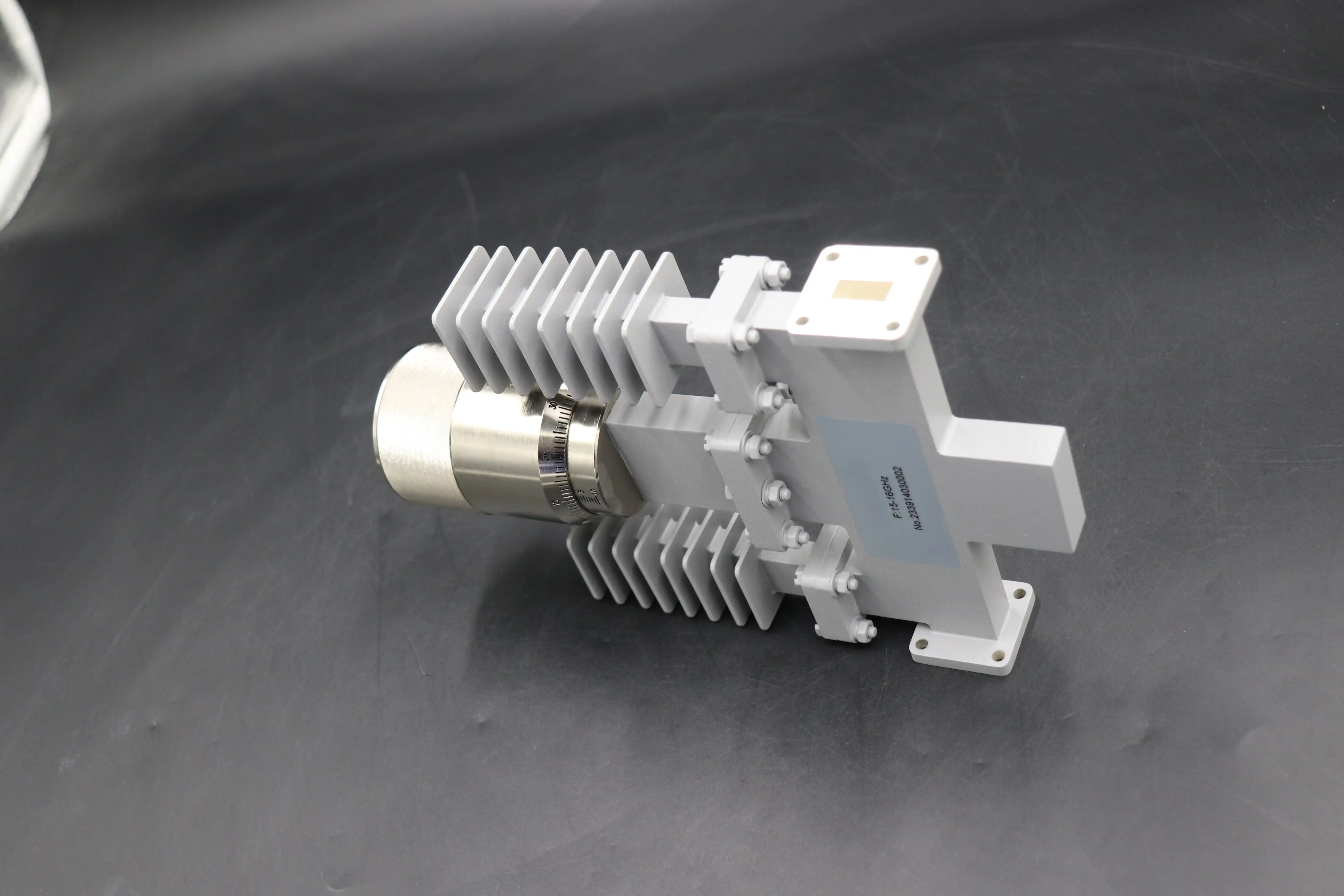
The way electromagnetic fields are spread out in rectangular waveguides can be predicted based on the mode of operation, which is usually TE10 for everyday use. The electric field is strongest in the middle of the waveguide and weakens as it moves toward the walls. This gradient is used by resistive card placement to let you change the reduction in steps. Precision mechanical drives, like micrometer screws or motorized actuators, are used in more advanced designs. These allow for positioning accuracy within micrometers, which means that premium units can attenuate better than 0.1 dB.
Technical Deep Dive: How Resistive Card Position Tunes Attenuation Depth?
Resistive card attenuation is based on complicated interactions between electromagnetic waves that are spreading and materials that lose electricity. When radio frequency energy hits a resistant card, the electric field component causes surface currents that heat the card. This turns electromagnetic energy into heat that is lost. How much energy is changed depends on three main things: the strength of the electric field where the card is located, the properties of the resistive material, and the shape of the coupling.
Fixed attenuators have static loss values that were set when they were made, so they can't be used in different ways if the needs of the system change. In the past, methods involved keeping a lot of fixed-value units on hand or settling for less-than-ideal performance. Variable waveguide attenuators get around this problem by being able to be adjusted mechanically, but they can only work if the resistive cards are placed precisely.
The effective coupling coefficient between the waveguide mode and the lossy element changes when the resistor card is moved during operation. Near the waveguide wall, coupling is still weak because the card is in a field null area, which means there isn't much contact. The coupling gets stronger as the card moves toward the center of the waveguide because the intensity of the electric field rises in a way that follows rhythmic patterns. Because this relationship isn't linear, small changes in position near the center cause bigger changes in attenuation than changes in position near the wall. To keep the linear control response, careful mechanical design is needed.
Stability at different temperatures is another important thing to think about. High-power applications put a lot of thermal stress on the resistive card, which could change the material's properties or cause it to expand and move around. High-quality variable waveguide attenuators have thermal compensation methods like heat sinks, forced-air cooling, or temperature-stable resistive materials that keep the attenuation values the same across the temperature ranges needed for aircraft and defense uses.
Real-World Performance in Radar Calibration
Radar system tuning shows how important it is to place sensitive cards correctly in real life. Engineers have to check the output power accurately over dynamic ranges greater than 60 dB as part of the transmitter linearity characterization process. A variable waveguide attenuator placed between the transmitter output and the measuring equipment enables stepped power reduction. This protects sensitive instruments while allowing full performance mapping. Airborne weather radar calibration data shows that attenuation uncertainty stays below ±0.2 dB across 9-10 GHz operating bands, meeting strict measurement requirements. Positioning accuracy must be within 10 micrometers.
Frequency Response Considerations
Not only does the position of the resistive card change the attenuation level, but it also changes the frequency response properties. As the card goes deeper into the waveguide, it adds reactive parts that can change the insertion loss depending on the frequency. Well-thought-out designs keep this effect to a minimum by choosing the right resistive material and card shape, which keeps the frequency response flat across the entire waveguide span. Specifications usually promise less than 0.5 dB ripple across the operating band. This makes sure that wideband communication systems work as expected.
Selecting the Right Variable Waveguide Attenuator for Your Application
To pick the right variable waveguide attenuator, you need to carefully look at a number of technical factors that are in line with the needs of your application. The choice grid includes more than just the attenuation range; it also includes frequency coverage, power handling capacity, mechanical accuracy, and durability in harsh environments.
Compatibility with frequency bands is the main selection factor. Waveguides naturally select certain frequencies. Each standard size is best for a different band: WR-90 is best for X-band, WR-62 is best for Ku-band, WR-28 is best for Ka-band, and smaller sizes are best for millimeter-wave applications. The resistive card mechanism works best in the frequency range recommended by the waveguide, where single-mode propagation makes field distributions predictable. If you work outside of these bands, you run the risk of multimode transmission, which makes controlling attenuation harder and hurts VSWR performance.
Waveguide attenuators are different from coaxial alternatives because they can handle more power. The big size and air-dielectric design make it possible for better heat dissipation, which lets it work continuously at kilowatt power levels that would destroy coaxial components in seconds. This feature is especially useful for defense applications that test high-power transmitters, as well as for satellite communication ground stations that handle boosted transfer signals. It's important for procurement specs to make it clear the difference between average power values (set by thermal management) and peak power limits (set by voltage breakdown levels in pulsed applications).
Precision in mechanics has a direct effect on the accuracy and clarity of attenuation. Direct-reading models have calibrated scales that show attenuation right away, making them good for situations where adjustments need to be made by hand a lot. Micrometer-driven designs give up ease of use for better positioning accuracy, and fine-pitch drive systems allow attenuation precision below 0.05 dB for variable waveguide attenuators. Motorized versions have stepper motors and digital control interfaces that let them do automatic test routines in production settings or remote control in places that are hard to get to, like satellite terminals on rooftops.
When looking for parts for ruggedized applications, you can't forget about environmental requirements. Military and space systems need parts that can handle high and low temperatures, shock, vibration, and high altitudes. Sealed enclosures keep moisture and other contaminants out of the internal mechanisms, and materials that don't rust make sure they last in marine environments. These better specs come with higher prices, but they're worth it when you look at the cost over time and how reliable the product needs to be for mission-critical tasks.
Fixed Versus Variable: Cost-Benefit Analysis
Fixed waveguide attenuators are easy to use and have a lower unit cost, but you have to keep an inventory of them in a range of attenuation values. Variable units cost more to buy at first, but they give you more operational flexibility, which lowers the total cost of the system. A telecommunications test center might keep a dozen fixed attenuators on hand to cover all possible measurement situations. On the other hand, two or three-variable units would cover the same ground while making inventory management easier. In custom or low-volume applications where getting multiple fixed values would be too expensive, this trade-off becomes especially useful.
Installation, Calibration, and Maintenance Best Practices
The variable waveguide attenuator will work reliably for as long as it is used, as long as it is installed correctly. To keep insertion loss, VSWR, and possible damage to flanges from being too high, waveguide joints need to be perfectly aligned. Standard interface flanges, such as the UG-series for inch-sized waveguides or the IEC designations for metric standards, must fit together perfectly, with no gaps. They are usually held in place with measured pressure to make sure that the gaskets compress evenly and that the electromagnetic flow stays uninterrupted.
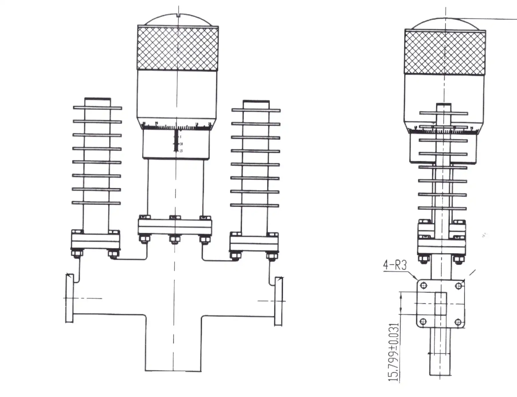
When the resistive cards are set up for the first time, they set the reference zero point for adjusting the reduction. Premium units come with factory-calibrated data that connects the mechanical position to the attenuation values. However, accuracy is confirmed in the field after the stresses of shipping and installation. Setting the attenuator to minimum insertion loss, checking the actual loss with a vector network analyzer, and then moving the attenuator to different positions while keeping track of insertion loss at different frequency points across the operating band are all parts of the calibration process. Deviations from the specifications mean that there are mistakes in positioning, mechanical wear, or effects from the environment that need to be fixed before the product can be used.
How often routine maintenance needs to be done depends on the duty cycle and the environment. Lab tools that work in controlled settings may only need to be inspected once a year, but units that are out in the field and have to deal with harsh conditions should be checked every three months. Maintenance plans include checking the flanges visually for damage or rust, making sure the mechanical drive works smoothly without binding, and testing the electrical system to make sure the attenuation is correct and the VSWR specs stay within the allowed range. Early detection of degradation stops catastrophic breakdowns during mission-critical activities.
Most failures are caused by mechanical problems and resistive card degradation. When high-power activity lasts for a long time, resistance materials can oxidize, which changes their attenuation properties over time. Particles in the air or outgassing in Hoover systems can contaminate the card and leave films on its surface, which can change its electrical properties. Drive screw seizure, bearing wear that causes positioning hysteresis, or spring failure in return systems are all signs of mechanical problems. Taking care of these problems quickly by cleaning, lubricating, or replacing parts keeps the measurements accurate and increases the service life.
Calibration Equipment and Procedures
For accurate calibration of a variable waveguide attenuator, you need measurement tools that can be tracked, like a vector network analyzer that can cover frequencies that are in the same band as the attenuator or higher. By using precision standards for two-port calibration, reference planes are set up at the attenuator flanges. This gets rid of the errors that come from test cables and adapters. Swept-frequency measurements show both how well the attenuation works and how flat the frequency response is. Time-domain analysis can find reflections from internal discontinuities that show that the mechanical components are not lined up correctly.
Conclusion
Variable waveguide attenuators can change the power of signals in demanding RF and microwave applications by placing resistive cards in a way that can be controlled over and over again. Understanding the physics behind field interaction, choosing parts that are right for the job, following strict installation and calibration steps, and working with reliable suppliers are the things that make system integration work. As millimeter-wave frequencies become more common in wireless communication and defense systems need better performance, precision-tuned variable waveguide attenuators play a bigger part. This means that smart purchasing choices are becoming more and more important to the success of programs.
FAQ
1. What advantages do variable waveguide attenuators offer over fixed designs?
You don't have to keep a lot of fixed-value attenuators on hand when you have variable waveguide attenuators. They allow for continuous adjustment over a wide range of attenuation levels with simple mechanical repositioning. This adaptability speeds up system calibration, lets signal level optimization happen in real time, and lowers the cost of inventory. Throughout the adjustment range, the resistance card system keeps a low VSWR and good power handling, which is hard to achieve with other variable attenuation technologies.
2. How does the resistive card position affect measurement accuracy?
Attenuation precision and consistency are directly related to how accurately the position is set. Attenuation changes of as little as 0.05 dB are possible with precision mechanical drives that can position themselves to the micrometer level. This is necessary for testing sensitive receivers and setting the right power level. When there is hysteresis in the positioning mechanism, like backlash in the drive screws or friction in the bearings, repeatability is lost. This is why high-quality mechanical building is an important design parameter.
3. Can variable waveguide attenuators handle high-power radar applications?
Waveguide design naturally supports high power levels by insulating with air and quickly getting rid of heat. Depending on frequency band and physical size, most units can handle steady wave power ranging from hundreds of watts to several kilowatts. In pulsed operation, they can handle peak power levels of up to tens of kilowatts. The material and mounting of the resistive card determine its thermal limits. For transmitter test applications, power handling specifications are very important for making choices.
Partner with ADM for Precision Variable Waveguide Attenuator Solutions
Advanced Microwave Technologies Co., Ltd has been providing high-precision variable waveguide attenuator solutions to the defence, aircraft, satellite communication, and research industries around the world for more than twenty years. Our ISO 9001:2015-certified manufacturing processes and state-of-the-art 24m microwave darkroom allow for full testing across 0.5–110 GHz, making sure that every unit meets strict performance requirements before it is shipped. Whether you need regular catalogue items or attenuators that are specially designed to fit your system, our expert team is here to help from the beginning of the specification process through installation and beyond. As a reliable variable waveguide attenuator manufacturer dedicated to quality, innovation, and customer success, we invite procurement professionals looking for reliable parts and a real partnership to email craig@admicrowave.com today to talk about how our services can help you reach your program goals.
References
1. Rizzi, P. A. (1988). Microwave Engineering: Passive Circuits. Prentice Hall, Chapter 7: Waveguide Attenuators and Phase Shifters.
2. Collin, R. E. (2001). Foundations for Microwave Engineering (2nd ed.). IEEE Press, Section 5.4: Variable Attenuators in Waveguide Systems.
3. Ginzton, E. L. (1957). Microwave Measurements. McGraw-Hill, Chapter 9: Precision Attenuators and Calibration Techniques.
4. Saad, T. S. (Ed.). (1971). Microwave Engineers' Handbook, Volume 1. Artech House, pp. 234-256: Variable Waveguide Attenuator Design Principles.
5. IEEE Standard 474-1973 (R2003). IEEE Standard Specifications and Test Methods for Fixed and Variable Attenuators, DC to 40 GHz.
6. Montgomery, C. G., Dicke, R. H., & Purcell, E. M. (Eds.). (1948). Principles of Microwave Circuits (MIT Radiation Laboratory Series, Vol. 8). McGraw-Hill, Chapter 11: Attenuators and Terminations.