





Best directional couplers for rf power monitoring systems
When you build or upgrade RF power tracking systems, the Directional Coupler is one of the most important parts that affects how accurate the measurements are and how reliable the system is. This passive device picks up signal energy moving through transmission lines without getting in the way of the main RF path. This lets engineers keep an eye on both forward and reflected power all the time. The best Directional Couplers have high directivity (often over 30dB), low insertion loss, wide frequency coverage, and strong construction, making them ideal for use in defence radar, satellite ground stations, and telecommunications infrastructure. To choose the right model, you have to balance technical details like coupling factor and power handling with buying issues like customisation support and supply chain timeliness. This affects both the performance of the system and the success of the project as a whole.
Understanding Directional Couplers and Their Role in RF Power Monitoring Systems
Directional Couplers function by electromagnetically coupling a main transmission line and a secondary sample line. This coupling mechanism takes out a controlled amount of the signal (determined by the coupling factor) while keeping the forward and reverse signal paths very separate. It has four ports: an input port, an output port, a coupled port, and an isolated port. When RF energy comes in through the input port, most of it goes to the output with little loss, but a known amount goes to the linked port for measurement reasons. The separated port stops reflected energy, which keeps the forward signal sampling from being harmed.
Understanding key performance metrics helps you choose the right components. The operating bandwidth is based on the frequency range. There are narrowband designs that work best for single-band uses and ultra-wideband designs that cover many octaves. Insertion loss measures how much power is lost along the main transmission path. For high-quality units, this loss is usually less than 0.2dB. The coupler's ability to tell the difference between forward and reflected signals is measured by its directivity. Values above 25dB guarantee accurate VSWR measurements. The coupling factor sets the power sampling ratio, which is usually between 6dB and 40dB, depending on how sensitive the monitoring needs to be.
Types of Directional Couplers and Their Design Advantages
Each type of coupling architecture is best for a certain type of application. Coaxial Directional Couplers work perfectly with normal 50-ohm systems that have SMA, N-Type, or TNC connections. These small units have insulated housings with parallel-coupled lines that work over a wide frequency range, from 500 MHz to 40 GHz. Their stripline or air-line design makes sure they have low passive intermodulation performance, which is very important for base stations that handle telecommunications, where signal integrity must be maintained.
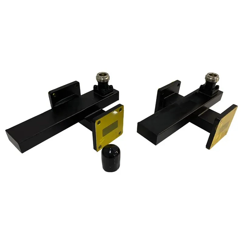
In high-power and millimeter-wave settings, waveguide-based couplers are the most common choice. These Broadwall Directional Couplers use multi-hole arrays on parallel waveguide walls to achieve high directivity of more than 40dB through Chebyshev or tapered coupling distributions. These structures are made of aluminium or brass and can handle constant power up to kilowatts while keeping insertion loss below 0.1dB. Crossguide Directional Couplers connect two waveguide sections at right angles to each other, sending energy through carefully machined holes in the wall of the two sections. When compared to parallel designs, this perpendicular layout has much shorter insertion lengths. This makes it possible to work with limited room in radar feed networks and satellite packages.
Hybrid and lumped-element couplers are made for lower frequency ranges and uses that need to save money. Hybrid designs combine segments of transmission lines with separate parts, which makes them work in lower frequency ranges. Lumped-element types use capacitors and inductors in small surface-mount packages. They are good for prototyping and putting together low-power circuits where the size of the part is bigger than its highest power handling capacity.
Comparison of the Best Directional Couplers for RF Power Monitoring in 2026
By looking at the top makers, you can see how different brands target different groups of customers by specialising in certain technologies and putting their products in the market. Krytar is known for its ultra-broadband designs that can cover frequencies from 0.5 to 40 GHz and have directivity requirements of up to 30dB. These designs are used by test labs and aerospace contractors who need single-component solutions for characterising multiple bands. Their tough aluminium housings can handle changing temperatures from -54°C to +85°C, which meets the MIL-DTL-85 weather standards that defence procurement teams require for systems that can be used in the field.
Mini-Circuits is the leader in the OEM integration market thanks to its standard coaxial models, quick delivery, and clear pricing. Their surface-mount Directional Couplers take up very little room on the board and keep performing the same way across all production levels. This is helpful for contract makers who are putting together RF subsystems with stable supply chains. The catalogue specifications clearly list the worst-case parameters instead of the most common ones. This lowers the uncertainty in qualification during the design validation phases.
Marki Microwave is an expert in high-frequency millimeter-wave Directional Coupler and couplers that go beyond 50 GHz. These are used in the new 5G infrastructure and car radar uses. Their patented designs make it possible for flat coupling across waveguide bands, which lets power tracking in wideband active antenna systems work correctly. Anritsu and Keysight place their coupler products in larger ecosystems of test equipment. They include calibration services and traceability documentation that metrology labs need to meet ISO/IEC 17025 standards.
Supplier Reputation and Datasheet Transparency Considerations
Real datasheets tell the difference between trustworthy manufacturers and commodity suppliers. Leading brands release full S-parameter files that cover a wide range of temperature and frequency levels. This lets you test the system using simulations before putting together a prototype. They list the maximum power ratings, VSWR limits at all ports, and coupling flatness standards. They also show clear derating graphs for the maximum power ratings. This makes the buying process safer, especially when adding couplers to complicated RF chains where the effects of how parts interact can hurt the overall performance.
When you compare Directional Couplers to other signal sampling methods, you can see when each one works best. Circulators offer better separation and can handle higher power levels, but they don't let you watch both the forward and reflected power at the same time, as couplers do. Resistive power splitters are cheaper, but they have a minimum insertion loss of 3dB, which is too much for receivers with limited sensitivity. When procurement teams look at bill-of-material trade-offs, they have to balance these functional differences with budget limits and technology needs that are specific to their system designs.
How to Choose the Right Directional Coupler for Your RF Power Monitoring Needs (Decision Support)?
Setting operating frequency limits is the first step in matching Directional Coupler specs to application needs. For C-band and Ku-band satellite ground stations, couplers that work from 4 to 18 GHz are needed. For 5G millimeter-wave systems, devices that work in Ka-band are needed. To account for manufacturing flaws and future system upgrades, procurement engineers should specify a frequency range that is 10% wider than the nominal operating bands.
In applications with limited power, insertion loss has a direct effect on link budgets. Receivers that boost weak signals can't handle any more loss. Choosing couplers with insertion loss below 0.15dB keeps signal-to-noise ratios that are important for long-distance communications. On the other hand, when ruggedization and thermal management are the most important things, high-power emitter tracking can handle a little more insertion loss.
Needs for measurement accuracy go up as requirements for directivity go up. To get rid of measurement mistakes caused by poor port isolation, laboratory-grade network analysers that measure reflection coefficients to within 0.01dB need coupler directivity levels higher than 35dB. Industrial power monitors that track the output of an amplifier for protection work well with 20dB directivity, which lets cost optimisation happen by loosening requirements.
Supplier Considerations for Supply Chain Optimization
Order minimums have a big effect on how long it takes to make prototypes and how much it costs to keep inventory on hand. For normal catalogue items, established makers usually set MOQs between 5 and 50 units. For custom configurations, they may need 100-piece pledges. Early on in the vendor selection process, procurement managers should talk about sample policies and prototype pricing structures while matching qualification numbers against production forecasts.
Lead times are very different for off-the-shelf and custom designs. Standard coaxial models can be shipped within two weeks from major distributors, which helps with quick product development. Lead times for waveguide couplers that are machined to specific flange types and frequency bands can be 8 to 12 weeks. For projects that need to be finished quickly, this means that material planning needs to start early. Suppliers that offer fast production services charge more, but they are worth it when prototype delays threaten to miss program goals.
Parts makers are different from catalogue sellers because they can customise their products. To meet the needs of each system, leading suppliers change coupling factors, connector types, mounting configurations, and frequency coverage for Directional Coupler. Our experienced technical team provides detailed engineering support. Before investing in tooling, they check to see if custom designs are possible and run simulations of them. This way of working together lowers the risk of development and makes sure that finished goods fit together perfectly with bigger parts.
Technical support, calibration services, and failure analysis are all parts of after-sales support. Reputable manufacturers have application engineering teams that help with installation problems and suggest the best ways to run the system. They give out calibration certificates that can be tracked back to national standards, which is important for regulated industries that need proof of measurement uncertainty. When failures happen in the field, a full study finds the root causes, which could be improper use, environmental stress, or manufacturing flaws. This lets corrective actions be taken that stop the failures from happening again across all production amounts.
Ordering and Procurement Insights: Where and How to Buy Directional Couplers?
Checking industry certifications and quality management systems is the first step in finding reliable suppliers. Getting ISO 9001:2015 certification shows that you are committed to using consistent manufacturing methods and practices for continuous improvement. RoHS compliance makes sure that products meet European and global rules about the environment. Defence companies also need suppliers to be registered with ITAR or have AS9100 aerospace certification. This means that only qualified suppliers can use certain distribution methods.
Authorised distributor networks cover more areas and offer localised help in ways that direct maker ties don't always be able to. Major franchisee wholesalers keep popular models in stock, ship the same day, and give established accounts good payment terms. They combine the needs of many customers into one demand, and sometimes they can negotiate big discounts that individual buyers can't get on their own. Checking the distributor's licence on the manufacturer's website stops the exposure of fake parts, which have become a major risk in global electronics supply chains.
Pricing structures show both how complicated the parts are and how the market is positioned. Standard coaxial Directional Couplers cost between $150 and $800, based on how well they work and what frequencies they cover. Waveguide models range from $1,200 to $5,000, depending on how much power they need to handle and how they are built. Custom designs come with engineering fees of $2,000 to $8,000, which are spread out over the number of orders. To get a good idea of how much the whole acquisition will cost, procurement teams should ask for itemised quotes that separate recurring unit costs from one-time engineering fees.
Balancing MOQs, Lead Times, and Inventory Strategy
Bulk order prices encourage people to make bigger purchases, but they also raise the costs of keeping goods and the risk of it going out of style. It is common for discounts to go down by 10% for 25 units, 15% for 100 units, and 20% for 500 units. When figuring out breakeven points, procurement analysts should weigh the savings from discounts against the costs of carrying them and the uncertainty of demand. As a middle-ground solution for high-mix, moderate-volume production environments, consignment inventory programs shift the costs of holding items to suppliers while guaranteeing availability.
Keeping track of changes in lead times keeps project plans safe from supply problems. Dual-sourcing strategies find other suppliers for important parts, keeping the competition high while setting up backup sources for Directional Coupler. Based on the standard deviation of the wait time and the variability of demand, safety stock estimates figure out the buffer inventory levels that meet service level goals without requiring too much working capital investment. We work closely with sourcing teams to set reasonable delivery dates, and we are open about material supply and production capacity limits throughout the order fulfilment cycle.
Conclusion
For RF power monitoring systems to choose the best Directional Couplers, technical performance parameters must be balanced with procurement factors such as cost, lead time, and supplier capability. Accurate measurement systems need to have high directivity, low insertion loss, and the right frequency coverage. Long-term buying success depends on seller quality certifications, customisation services, and quick support. As defence systems, satellite infrastructure, and wireless communications move toward higher frequencies and more complex architectures, Directional Coupler technology keeps getting better by supporting wider bandwidths, better power management, and smart monitoring features. When procurement professionals build ties with capable makers, their companies can get these new products and ideas faster, giving them a competitive edge through better system performance and operational efficiency.
FAQ
1. What insertion loss is acceptable for precision RF power monitoring applications?
Acceptable insertion loss depends on how sensitive the measurements need to be and how much money the link has to spend. Most high-performance monitoring systems can handle an insertion loss of less than 0.2dB, which doesn't have a big effect on the overall noise figure or the efficiency of the transmitter. In order to keep measurement accuracy when describing low-power devices, laboratory-grade uses need insertion loss of less than 0.1dB. When lowering costs is more important than getting the best performance, industrial monitoring systems with large link margins may be able to handle 0.3 to 0.5dB insertion loss.
2. Can directional couplers be customized for specific frequency ranges?
Manufacturers with a good reputation will change coupling factors, connecting types, and frequency bands to fit the needs of each individual system. Custom designs usually have lead times of 8 to 12 weeks and minimum order sizes between 25 and 100 units. As part of engineering support, electromagnetic simulations, prototype validation, and documentation packages that help with system integration are all available. With more than 20 years of experience working with microwaves, we can provide full OEM services that are tailored to meet exact technical requirements.
3. Which factors most significantly determine directional coupler directivity performance?
Directivity depends on how well the manufacturing process is done, how symmetrical the coupling structure is, and how the phase relationships between the coupling mechanisms change with frequency. By carefully controlling the aperture spacing and coupling coefficients, multi-hole waveguide designs get the best directivity. The quality of the material and the finish on the surface affect insertion loss, which in turn affects effective directivity. Matching the thermal expansion coefficients between linking structures is important for temperature stability because it keeps performance even when the world is very hot or very cold. When putting systems into the field, they will work reliably if you choose Directional Couplers that have written directivity specs across the full operational temperature range.
Partner with ADM for Superior Directional Coupler Solutions
Advanced Microwave Technologies Co., Ltd. (ADM) has been making high-precision Directional Couplers for mission-critical RF power monitoring systems for more than twenty years. As a reliable Directional Coupler manufacturer, we serve the defence, aerospace, satellite communications, and telecommunications industries around the world. Our customised solutions are backed by ISO 9001:2015 certification, and our state-of-the-art 24-meter microwave darkroom can test everything up to 110 GHz. As a Directional Coupler supplier, we can do rapid prototyping, offer flexible MOQs that can be adjusted to fit the size of your project, and provide expert technical support to help you optimise your specifications. Get in touch with our engineering team at craig@admicrowave.com to talk about your specific needs and request detailed datasheets. You can also learn how our proven quality, competitive pricing, and flexible delivery schedules can help strengthen your supply chain and ensure accurate measurements across your RF monitoring infrastructure.
References
1. Pozar, David M. Microwave Engineering, 4th Edition. Hoboken: John Wiley & Sons, 2011.
2. Rizzi, Peter A. Microwave Engineering: Passive Circuits. Englewood Cliffs: Prentice Hall, 1988.
3. Balanis, Constantine A. Advanced Engineering Electromagnetics, 2nd Edition. New York: Wiley, 2012.
4. IEEE Standard 287-2007. IEEE Standard for Precision Coaxial Connectors (DC to 110 GHz). Institute of Electrical and Electronics Engineers, 2007.
5. Collin, Robert E. Foundations for Microwave Engineering, 2nd Edition. New York: IEEE Press, 2001.
6. MIL-DTL-3922. Detail Specification: Couplers, Directional, Radio Frequency, Coaxial and Waveguide. United States Department of Defense, 2017.
YOU MAY LIKE
 VIEW MOREWaveguide Straights and Transitions
 VIEW MOREInflatable Straight Waveguide
 VIEW MOREWaveguide Coupling Fixed Attenuator
 VIEW MOREWaveguide Single Channel Rotary Joint
 VIEW MOREWaveguide Anti-leak Gasket
 VIEW MOREDouble Ridge Waveguide Bend
 VIEW MORECoaxial Broadband Circulator
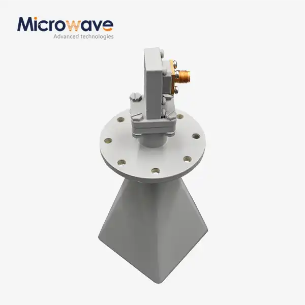 VIEW MORELow Side Lobe Diagonal Linear Polarization Horn Antenna
