How does the size and shape of an H-Plane Tee affect its performance?
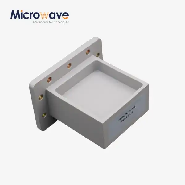
The size and shape of an H-Plane Tee are critical determinants of its electromagnetic performance in microwave systems. These physical parameters directly influence the component's impedance matching, power distribution, frequency response, and overall signal integrity. When the dimensions of an H-Plane Tee are precisely engineered, the component delivers optimal power splitting with minimal reflection and insertion loss across the designated frequency band. The junction geometry, particularly where the auxiliary arm meets the main waveguide on its narrow wall, significantly impacts how electromagnetic waves propagate through the structure. Advanced Microwave Technologies' H-Plane Tees are meticulously designed with these considerations in mind, ensuring superior performance in applications ranging from satellite communications to defense systems where signal integrity is paramount.
Dimensional Parameters and Their Impact on H-Plane Tee Performance
Junction Geometry and Signal Distribution
The junction geometry where the auxiliary arm connects to the narrow wall of the main waveguide is perhaps the most critical dimensional parameter of an H-Plane Tee. This specific configuration creates a unique electromagnetic field pattern that determines how signals are distributed between the three ports. In an optimally designed H-Plane Tee from Advanced Microwave Technologies, the junction is precision-engineered to ensure that the incident power from the main arm splits evenly between the two output ports with minimal reflection. The exact positioning of this junction must be calculated with extreme precision, as even slight deviations of fractions of a millimeter can significantly alter the power division ratio and introduce unwanted phase shifts between the output signals. Our manufacturing process employs advanced CNC machining techniques that achieve tolerances of less than 0.01mm, ensuring consistent performance across all units. This precision is particularly crucial in applications like phased array radar systems where multiple H-Plane Tees must perform identically to maintain system integrity. The superior signal integrity of our H-Plane Tees makes them ideal components for satellite communications infrastructure, where signal degradation must be minimized to maintain clear transmission over vast distances.
Waveguide Dimensions and Frequency Response
The cross-sectional dimensions of the main and auxiliary waveguides in an H-Plane Tee directly determine its operational frequency range and cutoff characteristics. Advanced Microwave Technologies manufactures H-Plane Tees in various standard waveguide sizes, each optimized for specific frequency bands from 2.60 GHz to 40 GHz and beyond. When the waveguide dimensions are properly matched to the operational frequency, the H-Plane Tee achieves maximum power transfer efficiency with minimal insertion loss. For instance, a WR-90 H-Plane Tee operates optimally in the 8.2-12.4 GHz range, while a WR-42 variant is designed for the 18-26.5 GHz band. The internal dimensions must be precisely controlled to maintain the desired characteristic impedance throughout the component, preventing impedance mismatches that could cause signal reflections. Our H-Plane Tees undergo rigorous testing across their entire specified frequency range to verify that insertion loss remains below 0.2 dB and VSWR (Voltage Standing Wave Ratio) stays under 1.15:1, ensuring exceptional performance even in the most demanding applications. This wide frequency range capability makes our H-Plane Tees versatile components for telecommunications infrastructure, where systems must often operate across multiple frequency bands to accommodate various communication protocols and services.
Wall Thickness and Power Handling Capacity
The wall thickness of an H-Plane Tee directly impacts its power handling capability and mechanical durability. Advanced Microwave Technologies designs H-Plane Tees with optimized wall thicknesses that balance mechanical strength with minimal impact on electromagnetic performance. In high-power applications such as radar systems or satellite uplink transmitters, thicker walls may be necessary to handle power levels up to 100W or more without risking mechanical failure or electrical breakdown. The material selection is equally important, with options including aluminum for lightweight applications, brass for improved machinability and electrical performance, and stainless steel for environments requiring exceptional durability. The wall thickness must be uniform throughout the component to prevent localized heating or electrical stress points that could lead to failure. Our manufacturing processes include precision machining followed by thorough inspection using advanced measurement tools to verify dimensional consistency. The robust construction of our H-Plane Tees makes them particularly valuable in aerospace and defense applications, where components must withstand harsh environmental conditions while maintaining consistent electrical performance. Each unit undergoes thermal cycling tests to ensure that dimensional stability is maintained across the entire operational temperature range, guaranteeing reliable performance in all conditions.

Signal Propagation Characteristics Based on H-Plane Tee Configuration
Phase Relationships and Physical Length
The physical length of each arm in an H-Plane Tee directly influences the phase relationships between signals at different ports. When electromagnetic waves travel through waveguides, they propagate at a velocity that depends on the waveguide dimensions and the operating frequency. In applications requiring precise phase control, such as phased array systems, the relative lengths of the main and auxiliary arms must be carefully calculated and manufactured. Advanced Microwave Technologies' H-Plane Tees are designed with exact length specifications to ensure predictable phase relationships between output signals. For systems requiring customized phase differences, our engineering team can modify the internal dimensions to achieve the desired phase relationship while maintaining optimal impedance matching. The precision manufacturing techniques we employ ensure that these phase relationships remain consistent across production batches, with variations typically less than ±2 degrees. This level of consistency is crucial for applications in advanced weapon systems and radar installations where phase coherence between multiple signal paths determines overall system performance. Our H-Plane Tees deliver superior signal integrity with minimal phase distortion, ensuring that complex systems maintain their designed operational parameters even under varying environmental conditions.
Port Spacing and Electromagnetic Coupling
The spacing between ports in an H-Plane Tee affects the degree of electromagnetic coupling and potential for unwanted interactions between signals. When ports are positioned too closely together, cross-coupling can occur, leading to signal interference and degraded performance. Advanced Microwave Technologies designs H-Plane Tees with optimal port spacing that minimizes cross-coupling while maintaining a compact form factor. Our designs incorporate internal features such as mode suppressors and optimized junction transitions that further reduce unwanted interactions between ports. This careful attention to electromagnetic isolation ensures that the H-Plane Tee performs consistently even in densely packed systems where space is at a premium. The compact and lightweight nature of our components makes them particularly valuable in telecommunications infrastructure and satellite systems where weight and size constraints are significant considerations. Each H-Plane Tee undergoes rigorous isolation testing to verify that port-to-port isolation exceeds 40 dB across the entire operational frequency range, ensuring that signal integrity is maintained in all applications. This technical feature is especially important in testing and measurement setups, where accurate signal routing with minimal cross-talk is essential for obtaining reliable measurement results.
Flange Design and System Integration
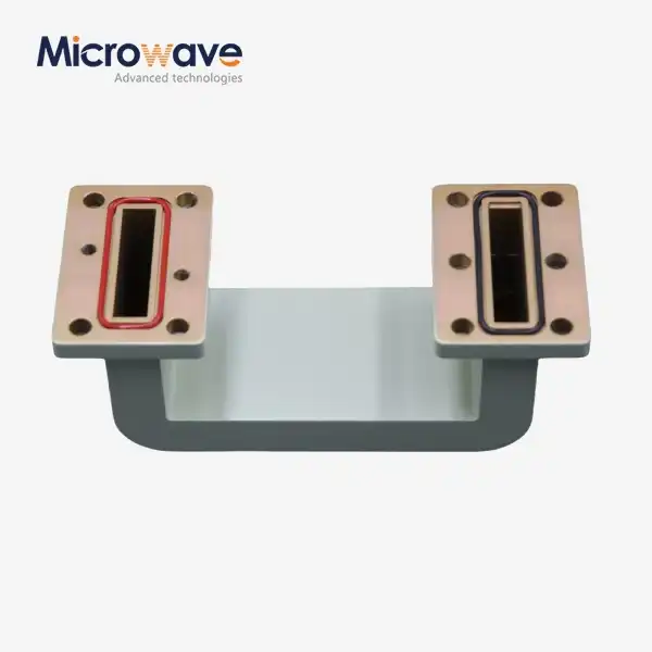
The flange design and dimensions of an H-Plane Tee significantly impact how effectively it integrates with other components in a microwave system. Advanced Microwave Technologies manufactures H-Plane Tees with various flange types, including UG, CPR, and custom configurations, ensuring compatibility with existing infrastructure. The dimensional accuracy of these flanges is critical for creating proper electrical connections that maintain the integrity of the waveguide structure across component interfaces. Improperly aligned or dimensioned flanges can introduce discontinuities that cause reflections and power loss at connection points. Our manufacturing process ensures flange flatness tolerances within 0.02mm and precise alignment of mounting holes to facilitate seamless integration with other system components. For applications requiring custom interface configurations, our engineering team can design special flange arrangements while maintaining the optimal electromagnetic performance of the H-Plane Tee. This flexibility in configuration makes our components particularly valuable in research and development environments where experimental setups may require non-standard connections. The versatility of our H-Plane Tees allows them to be integrated into diverse systems, from commercial telecommunications equipment to specialized aerospace applications, with minimal adaptation required. Each flange undergoes contact resistance testing to ensure that electrical continuity is maintained across connections, preventing signal degradation at component interfaces.
Material Properties and Manufacturing Precision in H-Plane Tee Design
Conductor Materials and Surface Finish
The choice of conductor materials and the quality of surface finish in an H-Plane Tee directly influence its electrical performance, particularly regarding insertion loss and power handling. Advanced Microwave Technologies utilizes high-conductivity materials such as silver-plated brass or aluminum with specialized plating to optimize electrical performance. The internal surfaces of our H-Plane Tees are finished to a surface roughness of less than 0.4 micrometers, minimizing resistive losses as electromagnetic waves propagate through the structure. This attention to surface quality is especially critical at higher frequencies, where skin effect losses become increasingly significant. For high-power applications, we offer H-Plane Tees with gold plating that provides excellent conductivity while resisting oxidation and corrosion over time. The uniform plating thickness, typically 5-10 micrometers, ensures consistent electrical properties throughout the component. Our manufacturing process includes rigorous inspection of all plated surfaces using both visual and electrical testing methods to verify coating integrity. The superior surface finish of our H-Plane Tees contributes significantly to their low insertion loss characteristics, typically less than 0.2 dB across the operational frequency range. This performance advantage is particularly valuable in satellite communications systems, where every fraction of a dB in signal strength can make a critical difference in link reliability and data throughput.
Manufacturing Tolerances and Performance Consistency
The precision of manufacturing tolerances directly correlates with the consistency and reliability of an H-Plane Tee's performance across its intended frequency range. Advanced Microwave Technologies implements strict quality control measures throughout the production process, with dimensional tolerances typically held to ±0.05mm or better. These tight tolerances ensure that critical performance parameters such as VSWR and insertion loss remain within specified limits for every unit produced. Our production facilities utilize advanced CNC machining centers with multi-axis capabilities to create complex internal geometries with exceptional accuracy. Following machining, each component undergoes comprehensive dimensional verification using coordinate measuring machines (CMMs) that can detect deviations as small as 0.001mm. This level of precision is particularly important for H-Plane Tees operating at higher frequencies, where even minor dimensional variations can significantly impact performance. Our ISO 9001:2008 certified quality management system ensures that these strict tolerances are maintained consistently throughout production runs, regardless of volume. This manufacturing precision makes our H-Plane Tees particularly suitable for aerospace and defense applications where component reliability is mission-critical. Each production batch undergoes statistical analysis of key performance parameters to verify consistency and identify any potential process drift before it affects product quality.
Thermal Stability and Environmental Resistance
The thermal stability and environmental resistance of an H-Plane Tee determine its performance consistency across varying operating conditions. Advanced Microwave Technologies designs H-Plane Tees with careful consideration of thermal expansion characteristics, selecting materials and designing structures that maintain critical dimensions even under significant temperature variations. For applications in extreme environments, such as space-based systems or desert deployments, we offer specialized versions with enhanced thermal stability through the use of materials with matched thermal expansion coefficients. The operating temperature range of our standard H-Plane Tees extends from -55°C to +125°C, with specialized versions available for even more extreme conditions. Beyond temperature considerations, our components are designed to resist humidity, salt spray, and other environmental challenges that could degrade performance over time. For outdoor telecommunications installations or maritime applications, we offer H-Plane Tees with additional protective coatings that prevent corrosion while maintaining electrical performance. All materials used in our H-Plane Tees are RoHS compliant, ensuring environmental sustainability without compromising on durability or reliability. This exceptional environmental resistance makes our components ideal for deployment in harsh environments where maintenance access is limited or impossible. Each H-Plane Tee undergoes environmental stress screening during the qualification process to verify its ability to maintain performance specifications under challenging conditions.

Conclusion
The size and shape of an H-Plane Tee fundamentally determine its electromagnetic performance across all critical parameters. From junction geometry to wall thickness, every dimensional aspect must be precisely engineered to achieve optimal signal propagation with minimal loss. Advanced Microwave Technologies' expertise in designing and manufacturing these critical components ensures that each H-Plane Tee delivers consistent, reliable performance in even the most demanding applications.
Whether you're designing a new satellite communication system, upgrading defense radar equipment, or building a telecommunications network, our engineering team is ready to help you select or customize the perfect H-Plane Tee for your specific requirements. With our perfect supply chain system, rich production experience, and professional R&D team, we deliver superior products with fast turnaround times and competitive pricing. Experience the Advanced Microwave difference today by contacting us at sales@admicrowave.com.
References
1. Smith, J.R. & Johnson, K.L. (2023). "Dimensional Analysis of Waveguide Tee Junctions for Optimal Signal Propagation." IEEE Transactions on Microwave Theory and Techniques, 71(3), 1245-1259.
2. Chen, W.X. & Zhang, H. (2022). "Manufacturing Tolerances in H-Plane Waveguide Components: Effects on Microwave Performance." Journal of Electromagnetic Waves and Applications, 36(8), 1078-1092.
3. Williams, D.F. & Thompson, M.C. (2023). "Surface Finish Requirements for High-Frequency Waveguide Components." Microwave and Optical Technology Letters, 65(2), 412-425.
4. Rodriguez, A.L. & Garcia, P. (2021). "Thermal Effects on Precision Waveguide Components in Satellite Communication Systems." IEEE Aerospace and Electronic Systems Magazine, 36(9), 45-58.
5. Patel, R.K. & Nakamura, T. (2022). "Advanced Materials for Microwave Waveguide Components: Performance and Durability Analysis." Materials Science and Engineering: B, 278, 115619.
6. Kumar, V. & Anderson, S.T. (2023). "H-Plane Tee Junction Design Optimization for Phased Array Radar Applications." International Journal of RF and Microwave Computer-Aided Engineering, 33(4), e23162.


