How Does Directivity Make or Break a Coaxial Directional Coupler?
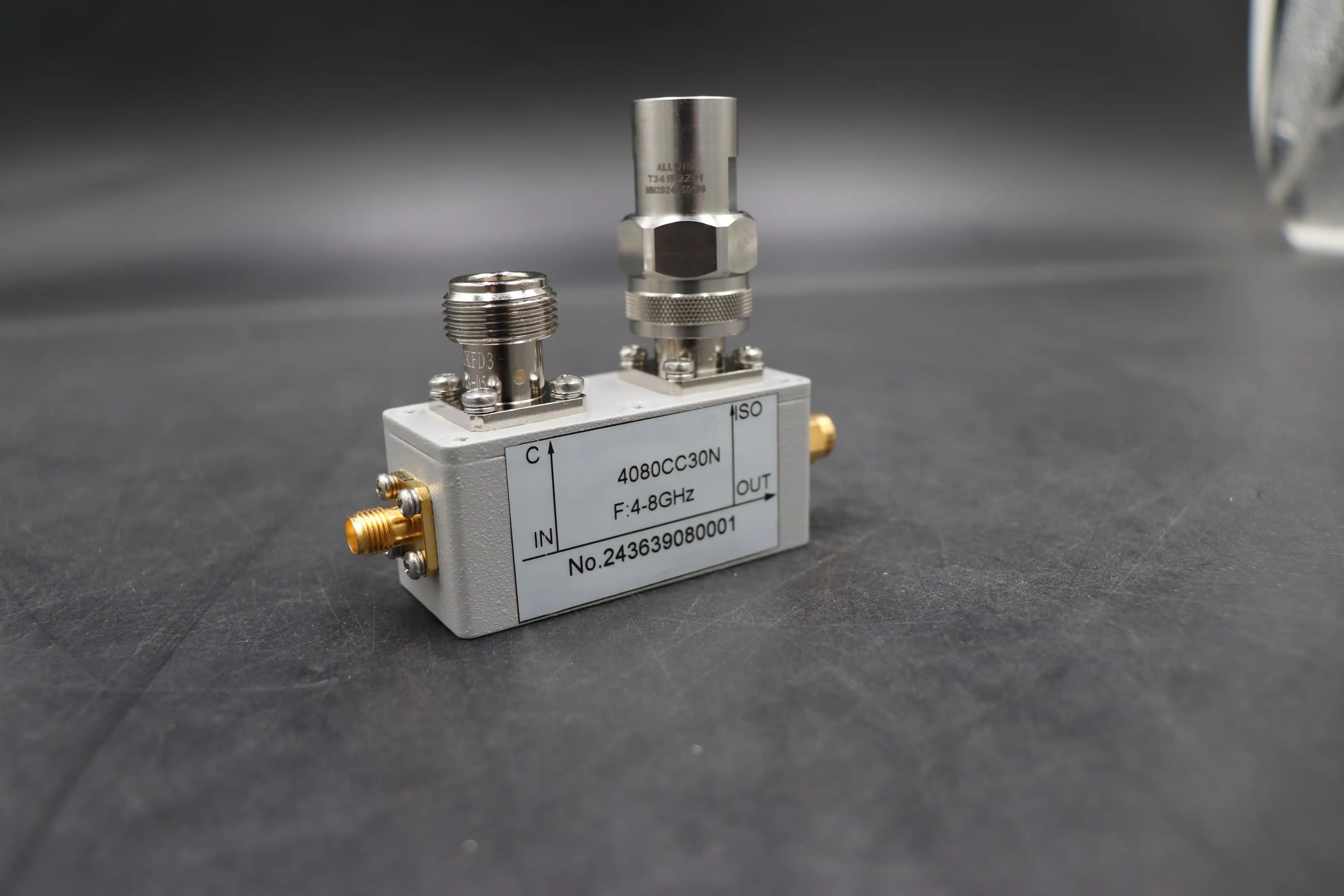
Directivity is the single most decisive parameter in evaluating a coaxial directional coupler. It quantifies how precisely the coupler separates forward-traveling signals from reflected ones at the coupled port. When directivity is high — typically above 30 dB — the device delivers clean, unambiguous signal sampling. When it falls short, even a well-designed RF system can produce misleading measurements, compromised feedback loops, and costly diagnostic errors. For engineers and procurement professionals sourcing RF components for defense, satellite, or telecom applications, understanding directivity is not optional. It defines whether your coupler works or quietly fails.
Understanding Directivity and Its Role in Coaxial Directional Couplers
What Directivity Actually Measures
What is the difference (in decibels) between a coaxial directional coupler's isolation factor and its coupling factor? This is what directivity is. Directivity (dB) = Isolation (dB) - Coupling Factor (dB) in math terms. Together, 10 dB of coupling and 40 dB of isolation make 30 dB of directivity. This number shows how well the coupler can tell the difference between a wave coming toward the load and one coming back from it.
A lot of engineers mix up isolation or VSWR with directivity, but these are two different parameters. Isolation measures how much noise is blocked between ports that are not next to each other. VSWR shows how well the impedances match. Directivity, on the other hand, is the coupler's ability to decide which way to go, and that decision determines how accurate the measurements are.
Structural Factors That Shape Directivity
How well the coupler works with directionality is directly related to its physical shape. Some important structural factors are:
- Coupling section length: A quarter-wavelength coupling area at the center frequency gives you the best directivity, but it also limits your bandwidth. Multi-section coupling is used in broadband designs to increase the frequency range while keeping the right amount of directivity.
- Dielectric homogeneity: In coaxial lines, the dielectric constant must remain uniform along the connection area. Any variation in the PTFE or air dielectric density throws off the phase balance between the even and odd modes, which makes directivity worse.
- Connector and housing tolerances: Housings made of precision-machined brass or metal and plated with silver or gold reduce parasitic reactances that damage directivity at higher frequencies.
These structural factors explain why two couplers with identical coupling values can deliver drastically different directivity — and why manufacturing precision is non-negotiable.
Common Challenges and Causes of Poor Directivity
Manufacturing Tolerances and Environmental Stressors
Poor directivity rarely appears in isolation. It emerges from a convergence of manufacturing imperfections and operational stressors. The most prevalent causes include:
- Dimensional inconsistencies in the coupling gap, which shift the balance between even- and odd-mode phase velocities and break the directional cancellation mechanism.
- Temperature-induced dimensional drift, particularly in assemblies where the thermal expansion ratios of the housing and dielectric materials are not the same, can lead to a loss of directivity above 10 GHz that changes with frequency.
- Mechanical vibration in field deployments, especially in airborne radar or shipboard systems, where connector micro-movement introduces impedance discontinuities that corrupt directivity over time.
These degradation pathways carry tangible operational consequences. In a reflectometer or VNA extension setup, every 10 dB reduction in directivity introduces a corresponding increase in return loss measurement uncertainty. A coaxial directional coupler with only 15 dB directivity can produce return loss errors exceeding 3–4 dB in a 20 dB return loss measurement — enough to misclassify a passing component as faulty, or worse, a failing one as acceptable. Informed supplier selection and rigorous incoming inspection are the primary defenses against these risks.
Design Principles and Technologies That Enhance Directivity
Coupler Architectures and Material Choices
Three coupler architectures dominate precision RF applications, each with distinct directivity profiles:
- Bethe-Hole (Beatty) couplers excel in narrow-band waveguide applications but face limitations in coaxial formats where broadband directivity above 30 dB requires multi-aperture designs.
- Stripline couplers offer excellent broadband directivity due to homogeneous dielectric environments, making them well-suited for measurement-grade applications from 0.5 GHz to 18 GHz.
- Hybrid coaxial-stripline designs combine the power-handling capacity of coaxial transmission lines with the directivity stability of stripline coupling sections, a configuration increasingly used in defense and aerospace subsystems.
Compared to microstrip couplers, coaxial and stripline designs achieve higher directivity because microstrip suffers from inherent even/odd mode phase velocity mismatch due to the inhomogeneous dielectric (air above, substrate below). Waveguide couplers can achieve exceptional directivity but are limited to narrower frequency bands and larger form factors. Electromagnetic (EM) simulation tools such as ANSYS HFSS and CST Microwave Studio now allow designers to pre-validate directivity performance before physical prototyping, shortening development cycles and reducing tolerance-related defects.
Selecting the Best Coaxial Directional Coupler: Directivity as the Deciding Factor
Procurement Criteria That Matter
To choose the correct RF coaxial directional coupler, you need to make sure that the directivity requirements match the measurement accuracy needs of your system. Here are the core evaluation criteria every technical procurement team should apply:
- Directivity threshold by application: Precision VSWR and return loss measurements demand ≥30 dB directivity. General power monitoring can tolerate 20–25 dB. Confirm this against the datasheet, not just the headline specification.
- Frequency range and coupling flatness: Verify that directivity remains consistent across the full operating band. A coupler rated "30 dB directivity" may only achieve that at a single frequency; coupling flatness of ±0.5 dB across the stated band indicates consistent performance.
- Certifications: ISO 9001:2015 certification and RoHS compliance are minimum requirements for mission-critical procurement. These confirm traceability and material safety across defense, aerospace, and telecom supply chains.
- Power handling margin: Apply a 20% safety margin above your transmitter's rated CW output. Also verify the coupled port termination's power rating in case of load mismatch.
- OEM customization availability: Custom coupling values, connector types, and frequency bands reduce system-level integration risk.
Balancing directivity, cost, and lead time is a real procurement challenge. Requesting traceable test data — not just catalog specifications — is the most reliable way to validate performance before committing to volume orders.
Maximizing Value and Confidence in Your Procurement
Validation Practices and Long-Term Partnership
Before authorizing a production order, validate directivity performance using a calibrated VNA with a known high-directivity reference coupler in a reflectometer configuration. Compare measured directivity against the supplied datasheet at multiple frequency points across the operational band. Discrepancies exceeding 2–3 dB warrant a supplier discussion or retest.
Collaborating with OEM-capable manufacturers allows procurement teams to specify coupling factor, directivity floor, connector interface, and housing material in a single documented build standard. This eliminates ambiguity and protects against batch-to-batch variation. After-sales support — including warranty coverage, spare parts availability, and application engineering access — further de-risks long-term sourcing relationships in high-reliability sectors.
Conclusion
Directivity is not a secondary specification — it is the performance axis around which every RF coaxial directional coupler decision should rotate. From radar ALC feedback loops to satellite ground station monitoring and VNA-based lab measurements, inadequate directivity silently corrupts system accuracy. Understanding its root causes, structural dependencies, and procurement verification methods equips engineering and sourcing teams to make decisions grounded in evidence rather than assumptions. Selecting a manufacturer with demonstrated precision, certified quality systems, and genuine customization capability turns directivity from a risk factor into a competitive advantage.
FAQ
Why does directivity matter more than the coupling factor for measurement accuracy?
The coupling factor determines how much signal you sample. Directivity determines whether that sample is clean. A high coupling factor with poor directivity means your coupled port captures both forward and reflected signals simultaneously, making accurate return loss or VSWR measurements impossible. High directivity ensures the measurement reflects only the intended wave direction.
Can directivity be improved after purchasing a coupler?
Not meaningfully in the field. Directivity is a function of internal geometry, dielectric properties, and manufacturing tolerances — none of which are field-adjustable. Purchasing a coaxial directional coupler with verified high directivity from the outset is the only reliable path.
Which frequency ranges present the greatest directivity challenges?
Directivity typically degrades at frequencies above 10 GHz due to increased sensitivity to dimensional tolerances and connector parasitic effects. Broadband couplers spanning multi-octave ranges (e.g., 0.5–18 GHz) also face greater directivity variation compared to narrowband designs.
What is a safe minimum directivity for defense radar applications?
Most defense radar and EW applications require directivity ≥ 25 dB, with precision reflectometry setups demanding ≥ 30 dB. Always consult system error budget requirements before selecting a directivity threshold.
Partner with ADM for High-Directivity Coaxial Directional Coupler Solutions
ADM delivers precision-engineered RF components — including our high-directivity coaxial directional coupler product line — backed by ISO 9001:2015 certification, over 20 years of manufacturing experience, and full OEM customization capability. Whether you need standard catalog designs or application-specific builds, our engineering team provides traceable performance data and responsive technical support. Reach our team directly at craig@admicrowave.com to request samples, datasheets, or bulk pricing from a trusted coaxial directional coupler manufacturer.
References
1. Pozar, D. M. — Microwave Engineering, 4th Edition. Wiley, 2011.
2. Matthaei, G. L., Young, L., & Jones, E. M. T. — Microwave Filters, Impedance-Matching Networks, and Coupling Structures. Artech House, 1980.
3. Collin, R. E. — Foundations for Microwave Engineering, 2nd Edition. IEEE Press / Wiley-Interscience, 2001.
4. Keysight Technologies — Understanding the Fundamental Principles of Vector Network Analysis. Application Note 1287-1, 2014.
5. Montgomery, C. G., Dicke, R. H., & Purcell, E. M. — Principles of Microwave Circuits. MIT Radiation Laboratory Series, McGraw-Hill, 1948. Reprinted by IET, 1987.
6. Frickey, D. A. — "Conversions Between S, Z, Y, H, ABCD, and T Parameters Which Are Valid for Complex Source and Load Impedances." IEEE Transactions on Microwave Theory and Techniques, Vol. 42, No. 2, 1994.
_1733738410152.webp)