High Q bandpass filter selection for communications
Selecting high-Q bandpass filters for modern communication systems demands careful consideration of technical performance and environmental resilience. WG Bandpass Filter technologies stand out for their exceptional frequency selectivity and low insertion loss, making them indispensable in defense radar, satellite ground stations, and telecom infrastructure. These waveguide-based solutions deliver superior signal integrity across demanding applications, from X-band radar systems to millimeter-wave satellite links, where precision and reliability cannot be compromised.
Understanding High Q WG Bandpass Filters: Working Principles and Key Features
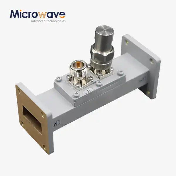
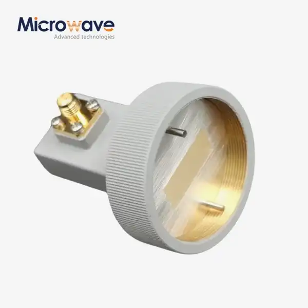
Waveguide bandpass filters work by using the way electromagnetic waves travel through hollow metal structures to make clear frequency separations with little data loss. Unlike surface-mounted options, these filters keep electromagnetic energy inside carefully machined holes. In most cases, they achieve quality factors above 5,000.
Electromagnetic Confinement and Selectivity
Cutoff frequencies and passband features are set by the physical shape of waveguide devices. When radio frequency energy comes into the waveguide cavity, only frequencies that match the resonant modes can travel well. Signals that are outside of these frequencies are severely attenuated. Maxwell's equations control this natural filtering process that makes steep skirt selection possible that can't be achieved with lumped-element designs. Our test labs make sure that insertion loss is less than 0.5 dB across all operating bandwidths. This is very important for satellite uplink chains, where signal preservation at every decibel level is very important.
Material Selection and Power Handling
Aluminum and brass are commonly used in business settings because they are good at conducting electricity and can be easily machined. Defence contractors often ask for copper that has been silver-plated so that high-power radar transmitters that handle kilowatts of continuous power work better. Temperature coefficients of these materials have a direct effect on how stable a filter is. Our ISO 9001-certified production methods keep dimensional errors within 0.001 inches, which means that our filters work the same way from -40°C to +85°C. This level of accuracy is important for tracking satellites through daily thermal cycles or for airborne radars that work in places from the Arctic to the desert.
X-Band Applications and Beyond
When it comes to waveguide filters, the X-band frequencies between 8 and 12 GHz are ideal. This spectrum is used a lot by defense surveillance platforms, weather monitoring systems, and maritime navigation radars. Our 24-meter microwave lab lets us measure the exact far-field antenna pattern at these frequencies, making sure that adding filters doesn't change the way the system radiates. Waveguide solutions have 15-20 dB better out-of-band rejection than microstrip filters that take up the same amount of space on the PCB. This is very important when adjacent channels carry sensitive intelligence data or high-value commercial traffic.
How to Select the Right High Q WG Bandpass Filter for Your Communication Needs?
When choosing bandpass filters for mission-critical systems, procurement engineers have to make a lot of choices. Technical datasheets only tell you part of the story. To find the best answers, you need to understand the application context.
Matching Q Factor to System Architecture
The needs for quality factors grow as the needs of the program do. To keep adjacent channel interference from happening, satellite transponders that multiplex dozens of carriers need Q factors above 8,000. Broadband telemetry receivers, on the other hand, may be able to work fine with Q around 2,000. Higher Q values mean narrower bandwidths and steeper rejection slopes, but they also make the device more sensitive to differences in how it was made. We find the best filters for frequency-hopping military radios, including WG Bandpass Filter solutions, by weighing selectivity against group delay flatness. This way, we can make sure that digital modulation schemes keep bit error rates below 10^-6 even when there is jamming.
Insertion Loss and Power Budget Analysis
Every part of an RF chain causes loss, which lowers the link margin directly. Waveguide filters usually have insertion losses of 0.3 to 0.8 dB, which is a lot less than ceramic or microstrip filters, which have losses of 1.5 to 3 dB. This difference adds up to a 12+ dB change in the noise figure over a 10-stage receiver front-end. This change determines whether weak satellite signals show up above thermal noise. Defence contractors working on the next generation of electronic warfare systems often ask for our insertion loss test data up to 110 GHz. They do this by comparing the measured performance to link budget spreadsheets before committing to production orders.
Environmental Qualification Standards
DO-160 environmental testing covers shaking, humidity, and electromagnetic interference, and it is required for commercial flight. Our screens are tested for 20G shocks and 500 hours of salt fog exposure, and these tests are confirmed by other labs. When research institutions build weather stations in Antarctica, they require connections and coatings that are tightly sealed and conformal. This keeps moisture out at temperatures as low as -60°C. These qualification records are important for procurement reviews because they show that the supplier met the reliability predictions made by the customer.
When you compare technology methods across different filter topologies, you can see where the speed limits are. Ceramic dielectric filters are small, but they have trouble above 20 GHz and can't handle a lot of peak power. Microstrip designs are easy to put on PCBs, but they lose power and have limited base capacity. Lumped-element LC filters work well for low frequencies but can't be used above 3 GHz because of parasitic reactances. Waveguide filters are most useful when the frequency is higher than 8 GHz, the power level is higher than 100 watts, or the Q factor is higher than 5,000. These are the conditions in which defence, aerospace, and satellite systems work.
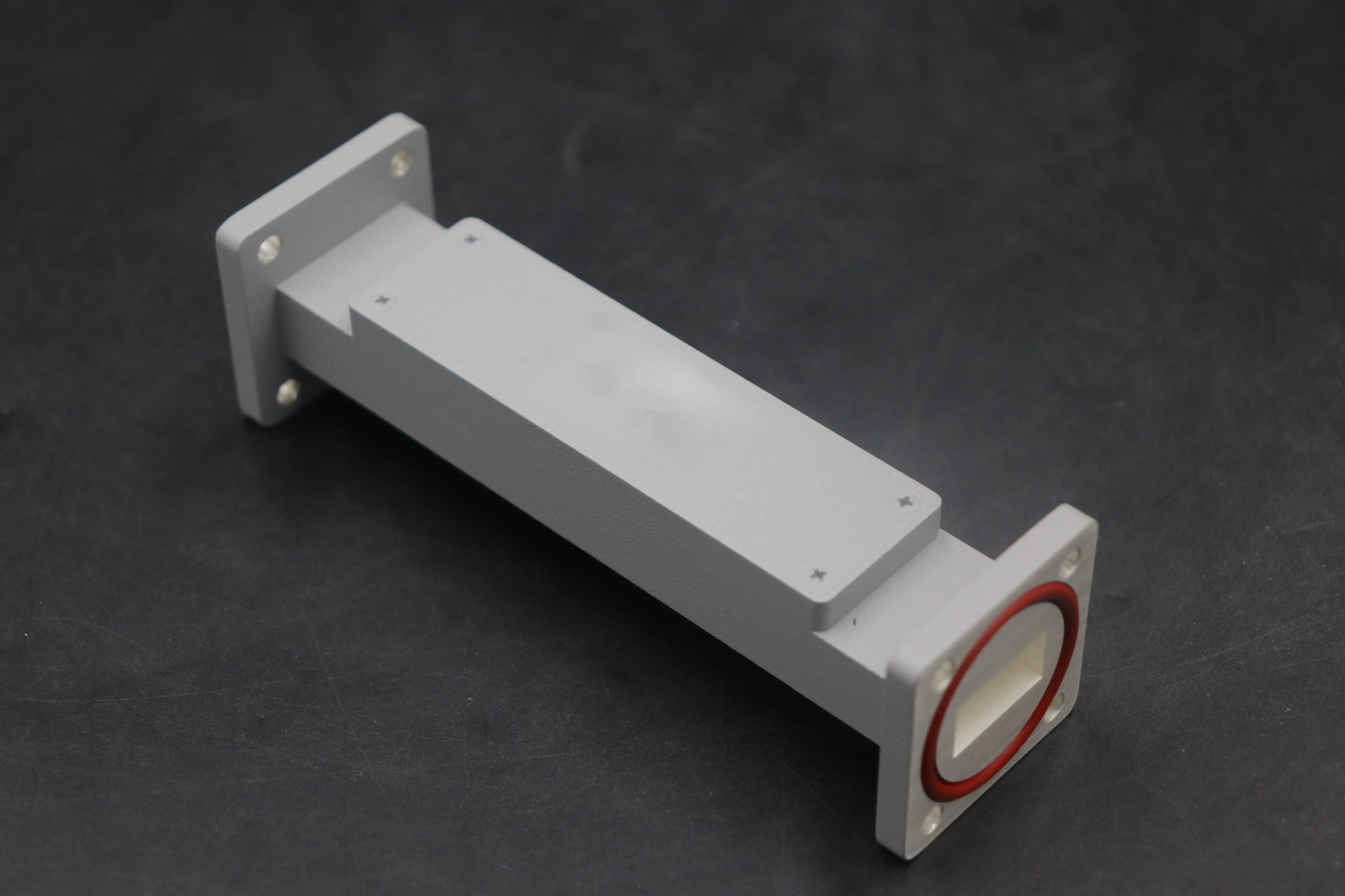
WG Bandpass Filter Design and Tuning: Practical Guidelines for Enhanced Performance
Specialized electromagnetic modelling tools and iterative prototyping are needed to turn system needs into filter designs that can be made. Our engineering team uses full-wave models to look at 3D field patterns inside waveguide cavities and predict how well the metal cutting will work before it starts.
Simulation-Driven Design Workflows
Ansys HFSS and CST Microwave Studio are two of the most important tools used to make filters today. Engineers use computer models to find S-parameters by changing temperature and frequency sweeps and coupling iris geometries, resonator dimensions, and tuning screw locations. Tolerancing analysis finds the most important measurements that need better control during machining, matching cost and performance. When aerospace OEMs ask us to make custom X-band filters with a 2% fractional bandwidth and 0.4 dB insertion loss, we go through about a dozen design options before deciding to make a prototype. This simulation-based method cuts development times from months to weeks, which is very important for programs that use fast prototyping.
Practical Tuning Techniques
Even with precise CNC cutting, theoretical performance can't be perfect; mechanical tuning makes up for differences in how the parts are made. For a WG bandpass filter, resonator screws change the frequencies of each cavity, and coupling screws change how energy moves between resonators. Our techs use vector network analyzers to measure reflection coefficients with a resolution of 0.01 dB. They do this while monitoring passband ripple and slowly adjusting the screws. In some cases, temperature correction needs bimetallic tuning elements that stop thermal expansion and keep the center frequency stable within ±5 MHz across all operating temperature ranges. This practical knowledge, built up over twenty years, is what sets application-optimized solutions apart from catalogue components.
A telecommunications contractor came to us with filters for a Ka-band satellite gateway that could handle 2 Gbps of traffic. Standard catalogue parts had too much group delay variation, which messed up high-order QAM formations. We changed the coupling topologies and added elliptic function responses with delayed characteristics that were equalized. Bit error rates went down by 40% after tuning, which let the client boost cluster density from 64-QAM to 256-QAM and four times the spectral efficiency. This case shows how domain expertise affects the choice of components, which in turn improves system performance and directly affects customer revenue.
Comparing WG Bandpass Filters with Alternative Solutions in Communications
When system builders look at filter technologies, they have to compare performance measures to things like cost, size, and how hard it is to integrate. Waveguide systems are best in certain areas, which is why they cost more per unit.
Performance Benchmarking Across Technologies
Microstrip filters made on Rogers substrates work pretty well up to 30 GHz, but their quality factors are only 200 to 500, which is too low for thick channel spacing. Ceramic monoblock filters can handle 1,000 Q factors, but they can only handle milliwatts of power, which makes them unsuitable for use in transmitters. Lumped-element designs with chip capacitors and inductors work for cell phone base stations below 6 GHz, but at microwave frequencies, they lose signal and are hard to predict. Waveguide filters regularly offer Q factors above 5,000, power handling above 1 kilowatt, and temperature stability within ±0.01%, which is something that other topologies can't do in demanding situations.
Supplier Evaluation Criteria
Aside from technical datasheets, procurement managers look at how strong the supply chain is and how well the quality systems work when evaluating vendors. RoHS compliance proves that a company cares about the environment, while ISO 9001 approval shows that its manufacturing processes are organized. Minimum order numbers limit the variety of prototyping that can be done. For research and development projects, we can take orders for a single unit, and for production runs of 500 or more pieces, we offer bulk discounts. A warranty that lasts between 24 and 36 months protects against early failures, which is very important when installing filters in satellite payloads that will be used for ten years. How quickly a vendor responds to technical support issues often determines which vendor is chosen. Our applications engineers give insertion loss predictions within 48 hours, which speeds up the design cycles for our customers.
Getting B2B microwave parts can be hard because of global logistics. Lead times range from six weeks for regular catalogue items to sixteen weeks for custom designs that need special tools. Long production processes don't work with "just-in-time" manufacturing, so smart inventory placement is needed.
Pricing Structures and Cost Drivers
Waveguide filter prices are based on the cost of materials, the difficulty of manufacturing, and the cost of tests. Eight-pole circular filters with strict requirements cost more than $3,000 each, while simple two-pole types cost around $800 each. Silver plating costs 20–30% more, but it lowers insertion loss by 0.1 dB, which is worth it for satellite transponders whose link budgets are measured in tenths of a decibel. Most volume savings start at 50 pieces, which cuts the cost per unit by 15 to 25 percent. When aerospace integrators ask for production runs of 500 units, we discuss framework deals that lock in prices for 18 months. This gives budgets peace of mind when metal prices change.
Authorized Distribution and OEM Partnerships
Buying from well-known manufacturers guarantees real parts with full documentation for tracking them back to their source. It's possible for fake RF parts to get into grey markets, where they work poorly and put system security at risk. Our tracking system for serial numbers connects each filter to its calibration certificates, material test reports, and environmental qualification data. This meets the needs of defence contractor audits. Through OEM relationships, we've been able to make customizations possible. For example, we've worked together to create integrated feed networks for phased array antennas by putting filters inside beamforming units to reduce interconnect losses. This collaborative approach speeds up time-to-market and lowers the cost of procurement for customers.
Global Shipping and After-Sales Support
To ship things internationally, WG Bandpass Filter products need to be carefully packed so that shocks don't damage precision-machined parts. Custom foam inserts and moisture barrier bags that have been approved by ISTA 3A transport tests are used by us. Customers in North America and Europe can get express shipping through FedEx or DHL within five business days, which helps with urgent retrofit programs. On-site setup help is part of our after-sales support. Our field techs have gone to remote ground stations in Alaska and French Guiana to check the performance of filters while they were in use. Customers stay with the company for a long time because of their complete service mindset. For example, 70% of aircraft OEM accounts place repeat orders.
Conclusion
High Q waveguide bandpass filters are the best for communication systems that need to keep signal integrity, handle a lot of power, and be resistant to environmental damage. Their electromagnetic confinement principles provide selectivity and low loss that can't be matched by other technologies. This makes them essential for use in defense radar platforms, precision instruments, and satellite ground infrastructure. A good procurement process balances technical requirements with cost, lead time, and the supplier's abilities. We have been making things for 20 years, have quality systems that are ISO-certified, and can measure up to 110 GHz. This makes us a trusted partner for global B2B clients who need to make tough choices about where to get RF components.
FAQ
1. What differentiates WG bandpass filters from ceramic or microstrip alternatives?
Waveguide filters use circular metal structures to confine electromagnetic energy, and they can handle more than 5,000 Q factors and 1 kilowatt of power. Ceramic screens are small, but they can only handle milliwatts of power and have Q values around 1,000. Microstrip designs are easy to put together, but they lose power and suffer from temperature shift and substrate losses. For high-frequency, high-power uses, waveguide options are better.
2. How does a high Q factor improve communication system performance?
Higher Q factors lead to shorter bandwidths and higher rejection slopes, which lets multiplexed systems use smaller channel spacing. This selectivity stops interference from adjacent channels in satellite transponders and lowers receiver noise by blocking out-of-band emissions. Defense systems gain from better resistance to jamming, which keeps signals intact in dangerous electromagnetic settings.
3. What factors influence insertion loss in waveguide filters?
Insertion loss is mostly controlled by the material's conductivity, the quality of the surface finish, and the coupling topology. Compared to bare aluminium, copper that has been coated with silver lowers resistive losses. Current crowding effects are kept to a minimum by precision cutting and keeping the surface roughness below 32 microinches. Multi-pole designs naturally have more loss than simple two-pole designs, so performance has to be traded off when the specifications are being made.
Partner with ADM for Superior WG Bandpass Filter Solutions.
When it comes to mission-critical transmission, Advanced Microwave Technologies Co., Ltd. makes the best waveguide bandpass filters in the business. Our production is ISO 9001-certified, and we have a 24-meter microwave lab that can test up to 110 GHz to make sure that every part meets the highest performance standards. Our expert team can help you with rapid prototyping, volume production, and full technical support, whether you need a catalogue of X-band filters or OEM designs that are completely unique to your needs. Flexible MOQs, clear pricing, and global shipping skills are all good for procurement managers. Get in touch with craig@admicrowave.com right away to talk to one of our software engineers about your needs. As a reliable WG Bandpass Filter maker that works with defence, aerospace, and satellite industries around the world, we can turn your needs into high-performance, dependable solutions.
References
1. Matthaei, G.L., Young, L., and Jones, E.M.T., Microwave Filters, Impedance-Matching Networks, and Coupling Structures, Artech House, 1980.
2. Cameron, R.J., Kudsia, C.M., and Mansour, R.R., Microwave Filters for Communication Systems: Fundamentals, Design, and Applications, Wiley-IEEE Press, 2018.
3. Hong, J.S. and Lancaster, M.J., Microstrip Filters for RF/Microwave Applications, John Wiley & Sons, 2001.
4. Levy, R., "Filters for Communications Satellites," IEEE Transactions on Microwave Theory and Techniques, vol. 65, no. 6, 2017.
5. Rhodes, J.D., Theory of Electrical Filters, John Wiley & Sons, 1976.
6. Snyder, R.V., "New Application of Evanescent Mode Waveguide to Filter Design," IEEE MTT-S International Microwave Symposium Digest, 1997.