Fixed or Variable? Choosing Waveguide Attenuators for Test Benches
When building or upgrading an RF test bench, one question surfaces almost immediately: should you use fixed or variable waveguide attenuators? The answer shapes your signal control strategy, measurement repeatability, and long-term procurement costs. Waveguide attenuators reduce signal power within a hollow metallic transmission line, maintaining system integrity across microwave frequency bands. Unlike coaxial attenuators, they handle higher power levels with lower insertion loss — a decisive advantage in X-band and Ku-band environments. This guide walks through everything you need to make a confident, technically sound decision.
Understanding Waveguide Attenuators: Basics and Applications
A waveguide attenuator controls the output signal level by absorbing a certain amount of electromagnetic energy as it travels through a rectangular or circular waveguide. When compared to coaxial or inline attenuators, which use resistive elements in an insulating medium, this function is very different. To get rid of power, waveguide designs use resistive vane or card structures placed inside the guide's cross-section. This works well at microwave and millimeter-wave frequencies.
X-band (8–12 GHz): Accurate attenuation in this band is very important for radar calibration, testing satellite ground stations, and setting up labs for electronic warfare. When stable loss values are needed over many test rounds, fixed pad attenuators work best in this situation.
Ku-band (12–18 GHz): Tight attenuation tolerances are needed for testing satellite payloads and VSAT systems. For dynamic signal-level calibration in this range, models that can be changed continuously down to 0.1 dB resolution are highly valued.
In bench setups, both fixed and changeable types are important. Fixed models give a fixed dB value, while variable attenuators let you make changes continuously or in steps. This is the main difference that affects all decisions made afterward about buying.
Key Criteria for Choosing Between Fixed and Variable Waveguide Attenuators
Selecting the right type is less about personal taste and more about making sure that the device's specs fit the way your test bench works. This test looks at how well the signal works, how much power it can handle, and how well it covers frequencies.
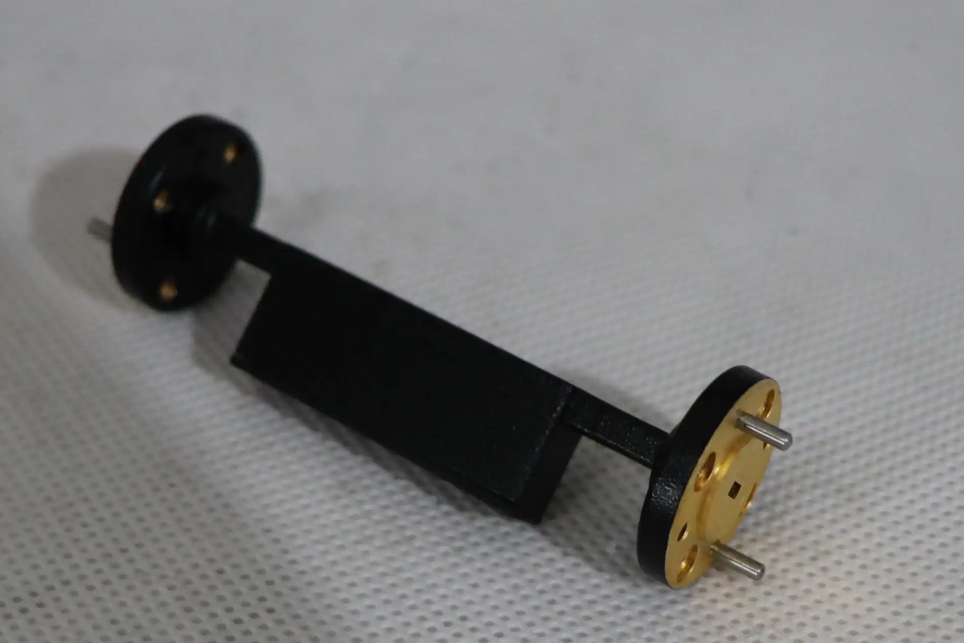
Here are the most important technical factors that should help you make your choice:
- Attenuation range and resolution: There are two types of attenuators: fixed and precision variable. Fixed attenuators offer clear values from 3 dB to 30 dB, while precision variable models cover ranges up to 60 dB with sub-0.1 dB resolution, which is necessary for measuring noise figures or characterizing gain.
- Repeatability and stability: Fixed pads are more stable over time because they don't have any moving parts or wear areas. Even though variable rotary vane waveguide attenuators can be adjusted, they can lose their calibration after a lot of mechanical cycling.
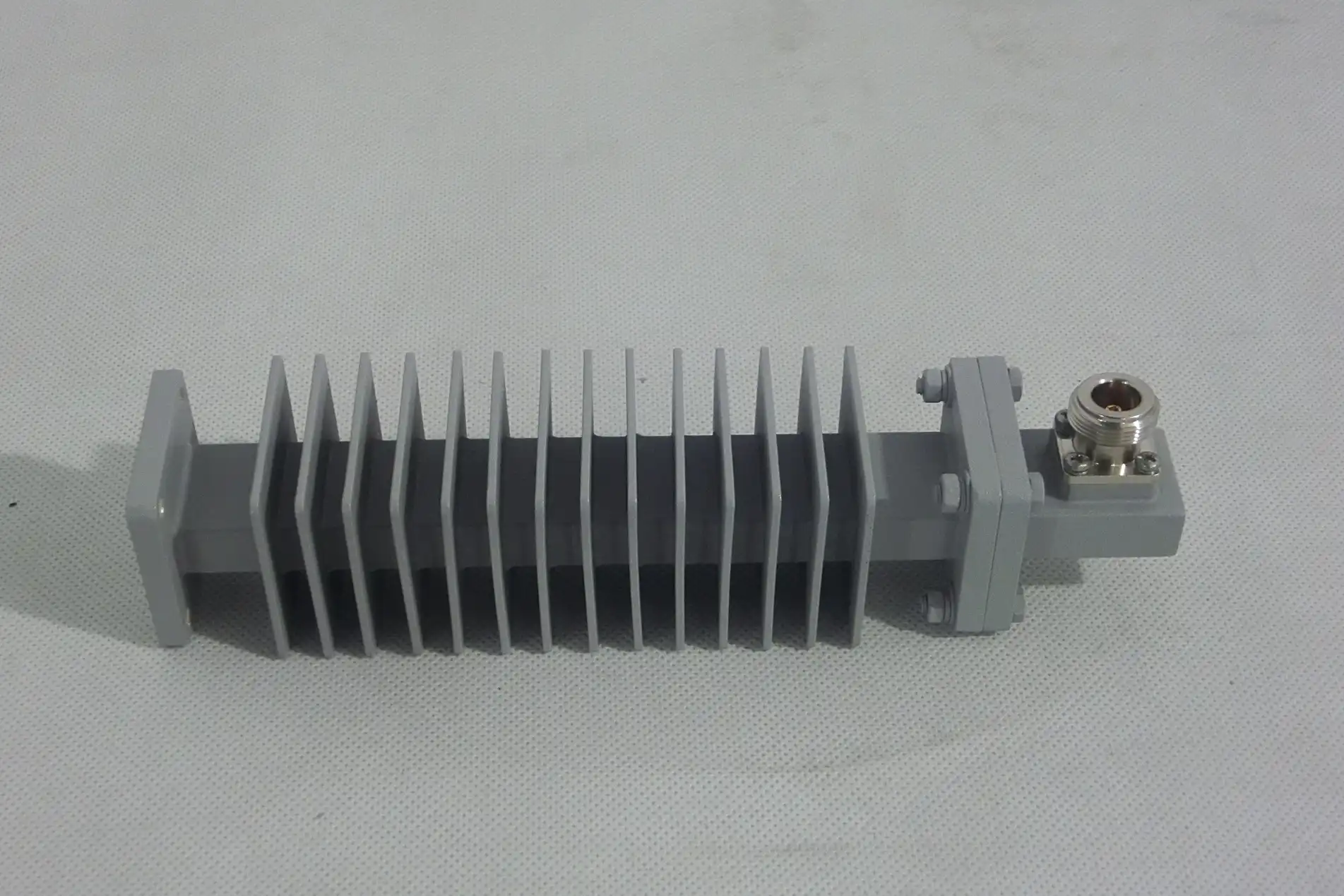
- Power handling capacity: For transmitter test sets, high-power fixed attenuators rated at 50W or more are used as usual. Most variable attenuators are only rated for low average power, usually less than 2W CW. This means they can't be used in places with a lot of power.
- Insertion loss: Fixed attenuators with precisely machined waveguide bodies consistently achieve insertion loss below 0.3 dB, keeping the accuracy of the signal path across frequencies.
In the end, these measures show which group works best for your bench. A test case that needs to use the same attenuation values over and over again benefits from hardware that stays the same. A variable model is the only one that can give the freedom needed for dynamic gain sweep readings or signal simulation tasks.
The dependability of the supplier makes this choice even harder. People who work in procurement should give more weight to vendors whose datasheets have been checked, whose calibration records can be tracked, and whose warranty terms are clear. A performance warranty that lasts for 12 months and application engineering support can make a big difference in lowering the total cost of ownership over the lifecycle of a product.
Installation and Testing Guidelines for Waveguide Attenuators
The accuracy of measurements is directly affected by how well waveguide attenuators are installed. If attaching or aligning is done carelessly, even a high-quality part will not work as well as it should.
Pre-Installation Checklist
Before you put any attenuator on your test bench, make sure the waveguide size is compatible (e.g., WR-90 for X-band, WR-62 for Ku-band), check the flange faces for burrs or contamination, and make sure the torque specifications for the flange hardware match the manufacturer's advice. For standard UG-style flanges, these are usually 4–6 in-lb.
Alignment and Mounting Technique
It is very important that the reduction ring and the component it fits are mechanically aligned. When there is misalignment, unwanted reflections happen, which raise the VSWR level above what is acceptable. If you can, use adjustment pins and be careful not to over-torque, as this can change the cutoff frequency behavior and damage the waveguide cross-section.
Use a vector network analyzer (VNA) to check speed after installation. Check that S21 is within ±0.5 dB of the quoted attenuation value across the working band and that S11 (return loss) is still greater than 20 dB. If there is any change, the flange contact and mounting hardware need to be checked again. These steps of proof protect both your trust in the measurements and the long-term health of the attenuator.
Market Options: Comparing Fixed and Variable Waveguide Attenuators for Procurement
The 2024 waveguide component market shows rising demand due to updating military equipment and expanding 5G backhaul. Standard fixed waveguide attenuators from well-known distributors usually have lead times of two to four weeks. Custom high-power or precision variable models, on the other hand, can take eight to twelve weeks, depending on the specifications.
Some brands, like Pasternack and Fairview Microwave, keep a large inventory of products with waveguide sizes WR-28 to WR-284. Standard values of off-the-shelf fixed attenuators are also available. Custom waveguide attenuator makers offer custom solutions with coatings made just for the application, non-standard flange setups, and wider frequency coverage for specialized uses like cryogenic test settings or ultra-broadband coverage.
Procurement teams should also check how responsive suppliers are. Buying from a company that offers technical advice before the sale, samples, and application support after the sale greatly lowers the risk of the purchase, especially when adding attenuators to complicated multiport test systems.
Advantages and Limitations: Fixed vs Variable Waveguide Attenuators in Test Bench Environments
When developers and customers know how each type works, they can choose hardware that will meet their long-term bench needs.
Fixed waveguide attenuators are known for being mechanically strong and stable in their calibration. Because they are passive and don't have any moving parts, they work reliably across thousands of connections without losing performance. They are the best choice for reference path calibration, power leveling, and isolator protection in both lab and production test settings because they have low insertion loss, behave consistently, and are easy to integrate.
When signal levels need to change quickly or exactly during a test process, variable attenuators are clearly more useful. Stepped attenuators offer repeatable discrete values through a mechanical or electronic control interface, while rotary vane designs let you change the attenuation in a smooth, continuous way. These models work well for integrating automatic test equipment (ATE).
There are real trade-offs. Fixed attenuators can't adapt to new test conditions without being physically replaced, which makes reconfiguring them in test environments with many possible outcomes take longer. When you use variable attenuators, things get more complicated. The rotary parts can wear out over time, and some designs have higher insertion loss (sometimes over 1.5 dB), which needs to be taken into account when planning system link costs.
In tough test settings, it's often best to use both types together: fixed attenuators are used to fix steady power-level offsets, and variable models are used to fix dynamic range issues. This mixed method gives you the most measurement options while still protecting the accuracy of the calibration.
Conclusion
There is no hard-and-fast rule for choosing between fixed and variable waveguide attenuators. It depends on the needs of your test lab. For setups that are used over and over, fixed models offer stability, low insertion loss, and low cost. Modern RF system evaluation often needs dynamic range control, which is what variable types offer. The best way to make sure your test bench works well is to make sure the part you choose fits your frequency band, power level, and measurement accuracy needs. Taking the time to look at supplier support, calibration paperwork, and shipping wait times will help both the buying process and the trust in your lab's measurements.
FAQ
What frequency bands are waveguide attenuators compatible with?
Waveguide attenuators are made for certain waveguide sizes that are linked to frequency bands. WR-90 works in the X-band (8.2–12.4 GHz), WR-62 works in the Ku-band (12.4–18 GHz), and other sizes work in the L-band through the W-band. Before you buy, you should always make sure that the waveguide size fits your working frequency.
How do I decide between fixed and variable attenuators?
A set attenuator is the best option if your test bench needs to reduce the signal consistently and over and over again at a known dB level. A variable attenuator gives you the freedom you need to change the signal level dynamically, like when you do gain sweeps or receiver sensitivity tests.
Can I request custom attenuation values or non-standard flange configurations?
Yes. Many companies that make waveguide attenuators can meet special requests, such as those for non-catalog dB values, high-power ratings, different flange types (CPR, UBR, cover flanges), and specific weather ratings. Orders that are made to order usually take between 4 and 12 weeks to complete, depending on how complicated they are.
What is a typical insertion loss specification for high-quality fixed waveguide attenuators?
Fixed waveguide attenuators that are well-designed have insertion loss below 0.3 dB across the rated frequency band and return loss above 20 dB. These values keep the signal path accurate in precise test sets.
Partner with ADM for Reliable Waveguide Attenuator Solutions
ADM has a carefully chosen range of fixed and variable waveguide attenuators designed for high-performance RF and microwave test benches. As a reliable waveguide attenuator provider, ADM offers confirmed datasheets, reasonable prices, and quick technical support for engineers and buying teams. Get in touch to talk about your project, ask for samples, or get a quick quote. You can reach our team at craig@admicrowave.com to look at the different configurations we offer.
References
1. Pozar, D. M. — Microwave Engineering, 4th Edition. Wiley, 2011.
2. Montgomery, C. G., Dicke, R. H., & Purcell, E. M. — Principles of Microwave Circuits. MIT Radiation Lab Series, McGraw-Hill, 1948. Reprinted by IET, 1987.
3. IEEE Standard 474 — Specifications and Test Methods for Fixed and Variable Attenuators, DC to 40 GHz. IEEE, 1973 (reaffirmed 2014).
4. Keysight Technologies — Waveguide Components and Measurement Fundamentals, Application Note 5989-5765EN. Keysight Technologies, 2019.
5. Collin, R. E. — Foundations for Microwave Engineering, 2nd Edition. IEEE Press/Wiley-Interscience, 2001.
6. Richardson RFPD — Microwave Passive Component Selection Guide for Test and Measurement Applications. Richardson RFPD Technical Publication, 2022.