Elliptical Waveguide Installation Best Practices
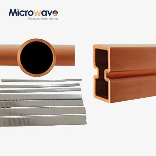
Installing an elliptical waveguide correctly is the cornerstone of achieving optimal signal transmission in mission-critical RF and microwave systems. These specialized transmission lines, characterized by their corrugated elliptical cross-section, combine the low-loss performance of traditional rigid waveguides with the mechanical flexibility needed for complex routing scenarios. At Advanced Microwave Technologies Co., Ltd, we've observed that proper installation directly impacts return loss, VSWR performance, and long-term system reliability. Our elliptical waveguides feature corrugated copper tubes with UV-resistant black polyethylene jackets, designed to endure harsh environmental conditions while maintaining signal integrity across frequencies up to 110 GHz.
Understanding Elliptical Waveguides and Installation Challenges
When it comes to sending high-frequency signals, elliptical waveguides are an advanced option that mostly work in the TE11 mode. Unlike coaxial cables, which lose a lot of signal above 3 GHz, these flexible transmission lines use waveguide physics to keep their low insertion loss even over long distances. The waveguide can bend around objects without losing its electrical properties because the copper tube is curved. This makes it very useful for installing satellite ground stations and radio feeds on towers.
Fundamental Electromagnetic Properties
The circular shape makes two separate bent planes, called the E-plane (minor axis) and the H-plane (major axis). There are strict minimum bend radius rules for each plane that must be followed. If these rules aren't followed, the corrugations could become deformed, which would mess up the spread of the electromagnetic field and lead to impedance problems. At Advanced Microwave Technologies, we make sure that our goods have tight physical limits so that they work the same way across the entire frequency range. VSWR is usually less than 1.15:1.
Common Installation Pitfalls
The growth and shrinkage caused by temperature make fitting very difficult. The curved form protects against physical stress like an accordion, but workers need to think about how the temperature will change when they secure the mounting spots. Another major worry is the entry of moisture; even small amounts of water mist inside the waveguide greatly increase loss and encourage internal rusting. When you join a connection incorrectly, reflection points form that lower the signal quality and can lead to power handling problems in high-power situations like satellite uplinks.
Environmental Stress Factors
Wind loads can cause tower-mounted devices to vibrate and wear out over time. Our waveguides have a UV-resistant plastic jacket that protects them from damage from the sun. However, workers must still make sure that the fixing points have enough pressure relief. When it's cold outside, ice loading adds weight and can cause too much bending if it's not supported properly. When it comes to defense and aircraft uses, shock loads need to be thought about even more during shipping and placement.
Pre-Installation Preparation and Site Assessment
Careful planning keeps you from having to do expensive rework and makes sure that the system works at its best. Before you buy waveguide components, we suggest that you do a thorough site survey and write down the full signal path from the equipment room to the antenna feed.

Physical Inspection Protocol
Unpack and inspect the elliptical waveguide immediately. Check for squeezed or kinked corrugations, damaged outer jacket, or reshaped connecting plates. Advanced Microwave Technologies tests all waveguides for VSWR across the frequency range before shipping. Shipping might cause damage. Compare the overall length to the criteria and ensure the chosen travel path can handle the bend radius constraints.
Environmental Constraint Evaluation
Extreme temperatures change both the mechanical flexibility and the steadiness of the electrical phase. When working in the desert, where temperatures rise above 60°C, you should account for heat expansion, which can make a 30-meter run longer by a few centimeters. In Arctic settings, it's important to make sure that the jacket is flexible. Our polyethylene mix stays flexible up to -40°C, but fitting should happen when temperatures are more comfortable, if possible. Write down the directions of the main winds and make sure that the fixing tools can handle the wind loads that are common in the area.
Tooling and Equipment Readiness
For the field closure of plugs, you need special flare tools. These high-precision tools make the curved end bigger so that it can fit the connection body while keeping the important size differences needed for low VSWR. When torque tools are set to the manufacturer's specs, they keep you from over-tightening, which can damage seals, or under-tightening, which lets pressure leaks happen. Before turning on the power, a pressure test kit with dry nitrogen makes sure the system is working properly. Vector network analyzers (VNA) that can measure spread frequencies can prove the quality of the system across the whole working band.
Precision Alignment and Assembly Techniques
Electrical efficiency is directly related to how well the connectors are aligned during system integration and connection. Small mistakes in rotational position or axial misalignment cause impedance discontinuities that can be seen as a drop in return loss.
Connector Flaring and Attachment
Pay close attention to depth and concentricity during the burning process. Before putting the link in place, clean out the waveguide of any metal shavings or other debris. To avoid stress points in certain areas, the flare must make even touch around the whole circle. Follow the manufacturer's torque order when putting on gaskets. Usually, start at 50% of the end torque and work your way up in a star pattern, then go to 75%, and finally 100%. This stepwise method makes sure that the compression is even and stops the seal from coming out.
Bend Radius Management
Most of the time, E-plane bending (against the minor axis) can handle smaller radii than H-plane bending. The minimum bend radii for our standard waveguides must not be exceeded, not even for a short time during installation. To keep the curves the same, use radius models or guides. Reverse turns and S-curves should not be close to each other because they create load buildup in one area. If you can't help but use complicated routes, you might want to ask for pre-formed parts when you buy them.
Securing and Strain Relief
Place support posts at the suggested spacing for the waveguide size, which is usually every 0.5 to 1 meter for horizontal lengths and every 1 to 2 meters for vertical runs. Instead of pushing the curved structure to fit into tight spaces, let it expand and contract naturally as the temperature changes. Install strain relief boots at the points where the fixed and movable parts meet. These boots spread mechanical stress over a bigger area. In tower setups that move because of wind, use the right silencing gear to separate the waveguide from the structure's movements.
Pressurization and Environmental Sealing
It is essential for long-term success to keep the internal atmosphere dry. Putting dry air or nitrogen under pressure stops moisture and raises the dielectric strength.
Pressure System Installation
Put pressure holes on the end of the tools where they can be easily monitored. Target pressures are usually between 5 and 10 PSI, which is enough to keep moisture out without putting too much stress on seals. Add a pressure indicator that can sound a warning to let repair staff know when there are leaks. Use desiccant breathers on air holes to let the pressure equalize when the temperature changes, but stop moisture from getting in. Before the system is thought to be sealed, pneumatic tests should keep the pressure at a certain level for 24 hours without any measurable loss.
Leak Detection and Remediation
During pressurization, put soap solution on all of the connecting points to help you see where the leaks are. Even small leaks will hurt performance over time as water builds up. Interfaces with gaskets, tools for fixing connectors, and field-cut ends are all common places for leaks to happen. Fix leaks by checking the state of the gasket, looking for dirt that is blocking the seal, and making sure the right torque values are being used. Instead of trying to fix broken connections or waveguide parts in the field, they need to be changed.
Post-Installation Testing and Validation
Full testing makes sure that the software meets performance requirements and finds problems before the system is put into service.
VSWR and Return Loss Measurement
Using a measured VNA to measure swept frequencies is the only way to be sure of the quality of an installation. At the equipment end, connect the VNA, and at the antenna end, use a precise load to close off the end. VSWR should stay below certain levels (usually 1.15:1 or 1.20:1) throughout the whole working band. Peaks in the VSWR chart show sources of reflection; the frequency of these sources is related to how far away the fault is electrically. Measurements of return loss are added to VSWR data. For good setups, return loss values usually exceed -20 dB.
Insertion Loss Verification
For loss, measure through-transmission (S21) of the elliptical waveguide. Compare your figures to the manufacturer's guidelines using the installation's length. Moisture, poor connection, or lattice damage can cause excessive loss. Advanced Microwave Technologies' waveguides must fulfil tight reduction standards, but installation affects their performance. Note the original measurements to compare later during repair rounds.
Power Handling Validation
Passive intermodulation (PIM) testing makes sure that connection contacts don't have any nonlinear joints that send out unwanted signals for high-power uses. At high power, low-level multipactor discharge can happen if the inside surfaces are dirty or if the connections don't make good contact. These things are controlled by the way we make our products, but outdoor pollution during installation can cause issues. During the first power-up, arc monitoring tools should be used to find any problems before they cause damage.
Comparative Insights: Elliptical vs. Other Waveguide Types
Learning about how to install different waveguide technologies helps procurement teams make smart choices that meet the needs of the project.
Circular Waveguide Comparison
Because they are balanced, circular corrugated waveguides can handle higher power levels. However, they don't have the best twisting patterns that elliptical designs do. Because circular waveguides need more careful route planning to avoid too much bending stress, they make installation more difficult. The circular shape from Advanced Microwave Technologies makes it easier to change directions in tight areas like tower wire trays. Both types need to be pressurized and tested in similar ways, but the connection tools are very different.
Rectangular Rigid Waveguide Trade-offs
The insertion loss is lowest in traditional rectangular waveguides, but they need a lot of flanged straight parts, bends, and turns. The cost of installation work goes up because each flange joint needs to be perfectly aligned, and each contact adds a possible reflection point. Because circular curved waveguides are flexible, they don't need many links in between. This cuts down on installation time and long-term failure points. In repair situations where current wire paths need to be followed, elliptical waveguides are much more flexible than rigid ones.
Lifecycle Cost Considerations
Even though elliptical waveguides may cost more to make at first than large-diameter coaxial lines, waveguide technology is cheaper in the long run. Less signal loss means that an amplifier isn't needed as much, which lowers both the cost of the amplifier and its working power use. Maintenance work is cut down because there are fewer link spots. When compared to fixed waveguide systems, our clients in satellite ground stations say that installation time is cut by 40–60%, which directly saves project costs. In military situations, defense companies like being able to quickly deploy.
Procurement Considerations for Installation Projects
Strategic planning for buying things makes sure that the right parts show up on time and meet technical standards.
Supplier Qualification Criteria
Verify that possible suppliers are ISO 9001-certified and follow RoHS. Our ISO 9001:2008 and RoHS certifications demonstrate Advanced Microwave Technologies Co., Ltd.'s commitment to quality and the environment. Check test data files to ensure manufacturing units and design samples meet electrical requirements. The supplier's bespoke lengths, connections, and fast sample turnaround demonstrate their flexibility to suit project objectives.
Lead Time and Inventory Management
Famous firms ship standard waveguide installations in two to four weeks. Custom designs with non-standard connector ports or lengths may take 6–8 weeks. You may wish to divide large orders into sample and production volumes. Due to our effective supply chain and 20 years of manufacturing expertise, Advanced Microwave Technologies can handle urgent demands while maintaining quality. Minimum order quantities vary by product. Discuss project timeframes early to align purchase strategies.
Technical Support and Documentation
Complete installation guidelines, including torque specs, bend radius limitations, and connection assembly processes, should be output. Access to application engineers during installation speeds field problem-solving. We provide experienced support from product selection to installation issues. Custom design lets you create condition-specific waveguide systems. Add pre-installed pressure fittings, specific socket placements, or outside protection to the jacketing. Documentation traceability aids defence and aircraft quality inspections.
Maintenance and Troubleshooting Post Installation
Regular repair makes systems last longer and stops them from breaking down when they're least expected, which can affect important processes.
Routine Inspection Schedule
Every three months, the elliptical waveguide's jacket structure is inspected for UV, wear, and animal damage. Make sure that the fixing gear is still there and no new stress points have formed. Slow pressure reductions indicate leaks and should be checked weekly. Annual VNA electrical testing detects speed loss before it affects system performance. In salty coastal areas, increase checks to once a month.
Diagnostic Techniques for Performance Issues
Sudden VSWR spikes indicate moisture or connection wear. Time-domain reflectometry (TDR) measurements reliably locate waveguide reflection sources. Gradual absorption increases over months indicate moisture buildup. Internal rust is shown by discoloured copper corrugations via transparent viewing apertures. Comparing current numbers to launch data might reveal trends.
Component Replacement Strategy
Multiple connections and disconnections wear down connectors, reducing electrical performance. Set replacement periods based on device use and link frequency. In covered settings, curved waveguides endure 20 years or more if properly maintained. Although our waveguides are durable, any parts damaged by outside impact should be replaced. Store additional short waveguide components and connection kits to save downtime during impromptu repairs.
Conclusion
The key to a successful elliptical waveguide installation is a combination of professional proficiency and meticulous attention to the installation process. These communication lines are much better than others because they are flexible and have low loss, but only if they are installed according to best practices. RF links that work reliably throughout their service life are made with careful planning before installation, precise alignment, thorough testing, and preventative maintenance. For difficult satellite communication, military, and telecommunications uses, Advanced Microwave Technologies not only offers high-quality curved waveguides but also the expert help needed to make sure the best installation results.
FAQ
Q1: How do I measure signal loss after installing an elliptical waveguide?
Connect a vector network tester that has been tuned to the working frequency band and measure the insertion loss (S21 parameter). Check the observed loss per meter against the specs given by the maker. Take into account the separate connection losses. When you do upkeep tests in the future, you can use the readings you took right after installation as a starting point.
Q2: What are the most common installation errors?
The most common mistake is going over the minimum bend radius limits, which results in lasting performance loss. Next comes incorrect connection torqueing, which can be either not tight enough to prevent pressure leaks or too much force that ruins seals. During field closure, contamination brings in moisture and debris. Fatigue failures happen when there isn't enough pressure release at changeover points.
Q3: How long do elliptical waveguides last in outdoor environments?
When used outside, waveguides that are properly fixed and have covers that are resistant to UV light usually last between 15 and 20 years. Our plastic jacketing doesn't break down in the sun or when the temperature changes. If pressure locks fail, salt rust may shorten the life of things in coastal areas. Longevity is increased by regular upkeep and fixing leaks right away.
Partner with ADM for Your Elliptical Waveguide Installation Projects
Every waveguide product that Advanced Microwave Technologies Co., Ltd. delivers is backed by more than 20 years of experience in the field. Our elliptical waveguides are made of bent copper and have a tough, UV-resistant jacket that gives them the freedom and longevity that your mission-critical setups need. As a reliable elliptical waveguide manufacturer, we keep our ISO 9001:2008 certification and RoHS compliance up to date. This way, the quality will stay the same from our factory to your site. Email craig@admicrowave.com to talk about the specifics of your project. Our engineering team gives you personalized advice on the types of connectors to use, how to make the cables longer, and which accessories to choose based on your specific needs. ADM provides the expert help and quick delivery that keep projects on track, whether you're putting in new telecommunications networks or improving satellite ground infrastructure.
References
1. Marcuvitz, N. (2017). Waveguide Handbook: Electromagnetic Theory and Design Principles. Technical Publishing International.
2. Institution of Electrical Engineers. (2016). IEC 60153 Series: Specification for Hollow Metallic Waveguides and Their Flanges. International Electrotechnical Commission Standards.
3. Silver, S. (2018). Microwave Antenna Theory and Design: Volume 12 of MIT Radiation Laboratory Series. Dover Publications.
4. Balanis, C. A. (2016). Advanced Engineering Electromagnetics, 2nd Edition. Wiley Professional Engineering Publishing.
5. U.S. Department of Defense. (2015). MIL-DTL-85: Detail Specification for Flexible Coaxial Transmission Line and Waveguide Assemblies. Defense Logistics Agency.
6. Pozar, D. M. (2021). Microwave Engineering: Theory, Analysis, and Design, 5th Edition. Academic Press Engineering Reference Series.