The Hidden Power of Waveguide Low Pass Filter: Revealing Their Secrets
When very strong radar systems send out a lot of signals at once or when satellite ground stations send uplink signals into space, unseen but very important electromagnetic problems appear. Waveguide Low Pass Filters are like quiet guards in these mission-critical systems. They let the signal frequencies that are wanted pass through smoothly while strongly refusing harmonics and false emissions that could damage the system. The strong passive RF parts use the electromagnetic qualities of waveguide shapes with curved ridges, tapered structures, or waffle-iron designs to provide better power handling and spectral purity. They are very important in defense radar arrays, satellite communications infrastructure, and precision measurement systems, where signal integrity can't be compromised because they stop harmonic distortion from high-power transmitters. This keeps them from breaking the rules and protects sensitive parts further down the line from damaging interference.
Understanding Waveguide Low Pass Filters: Fundamentals and Design Principles
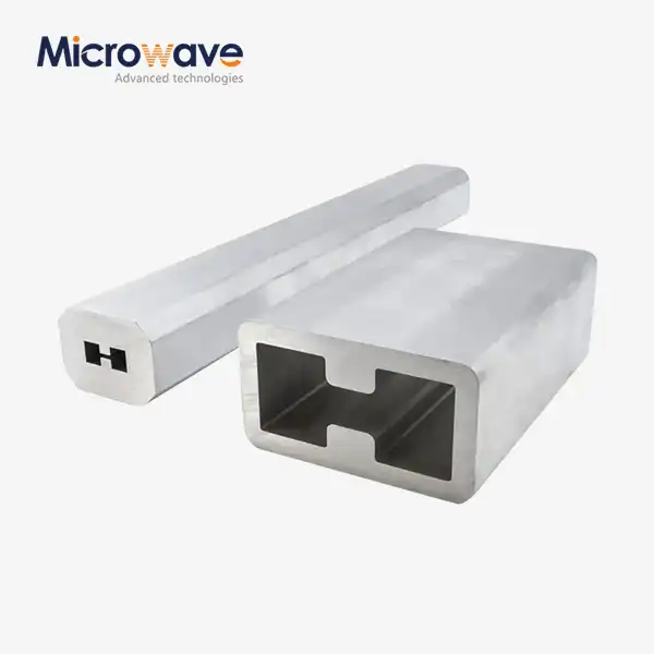
One way that these filters work is by using the special way that waves travel through waveguide structures. Waveguide setups are different from traditional coaxial or lumped-element designs because they use metal-enclosed pathways where electromagnetic waves can move with little dielectric loss. The cutoff frequency behavior is directly affected by the accuracy of the internal features' dimensions, which makes the frequency difference between the passband and stopband regions very clear.
Core Operating Mechanisms
Waveguide filters use impedance irregularities and evanescent mode decay to pick out specific frequencies. When signal frequencies drop below the cutoff level of the waveguide, electromagnetic energy quickly weakens instead of moving forward. Engineers add periodic obstacles, like eye plates, ridges, or corrugations, on purpose to make controlled echoes and resonances. Through phase opposition, these geometric changes create positive interference for the frequencies that are needed while canceling out unwanted harmonics.
The choice of material has a big effect on how well a filter works. The main structure is usually made of high-conductivity metals like copper or aluminum 6061-T6 material. Silver or gold plating is often added to make it stronger and lower skin-depth losses at microwave frequencies. Because it is so conductive, silver plating has the lowest insertion loss. Gold plating, on the other hand, is better at resisting rust in tough sea or aircraft settings. To keep scattering losses from lowering VSWR performance, the internal surface finish must stay below tight roughness limits, which are usually 32 microinches.
Design Parameters That Matter
When you're going for specific frequency answers, dimension tolerance becomes very important. Changes of a few microns in the internal hollow size or spacing of the ridges can cause the cutoff frequencies to move or the passband to ripple. Precision CNC machining and EDM (electrical discharge machining) are used by manufacturers to keep errors within ±0.001 inches. This makes sure that electromagnetic models of manufactured units match the real thing.
Another important thing to think about when designing is thermal stability. High-power apps produce a lot of heat, which causes thermal expansion, which changes the size of the inside. To make up for it, engineers choose the right materials and do temperature models. They may also add cooling openings or paths for forced air to flow. To keep the frequency stable across the working temperature ranges set out in MIL-DTL-85 environmental guidelines, temperature coefficients must stay within acceptable limits.
Application Domains
Radar stations with kilowatt to megawatt power levels need these filters to get rid of harmonic radiation that would mess up frequency bands next to them otherwise. Strict spectral cleanliness is needed for air traffic control systems, weather tracking networks, and navy spy platforms. After high-power amplifiers, satellite earth stations add Waveguide Low Pass Filters to make sure that only the basic transfer frequency gets to the antenna feed. This keeps harmonic energy from reaching orbital assets and breaking ITU radio rules.
These parts are needed for research institutions that do high-frequency readings to keep the signal integrity during experiments. Filters that can handle high peak powers and keep measurement accuracy down to fractional-dB levels are needed in particle reactors, plasma physics labs, and radio astronomy facilities.
Comparing Waveguide Low Pass Filters with Other Filters: Making Informed Decisions
System planners and procurement engineers often have to choose between different filter technologies. Understanding the trade-offs in speed helps you choose the best components for your system while staying within your budget.
When you compare Waveguide Low Pass Filters to other filters, you can make smart choices. Coaxial filters have small sizes and are easy to integrate, but they can't handle as much power. A normal cable low-pass filter could handle 100 watts of constant power, but waveguide filters can handle transmission powers of up to 10 megawatts and continuous powers of up to 10 kilowatts. Insertion loss also benefits waveguide designs, with normal levels below 0.1 dB in passband areas compared to 0.3 to 0.5 dB for coaxial options at the same frequencies.

Technology Comparison Matrix
Cavity filters have better selection through high-Q resonators, but they take up more space and have smaller bandwidths. They work great for tasks that need high skirt selectivity, but they don't have the broad harmonic reduction that waveguide designs naturally offer through their physical cutoff mechanisms.
Stripline and microstrip filters fit easily into printed circuit boards, which makes it easier to make systems that use less power. But because they are flat, they can only handle power levels below one watt, and at millimeter-wave frequencies, where conductor and dielectric losses rise, they cause more problems. Discrete capacitors and inductors used in stepped-element filters work well below 3 GHz, but they can't be used above that frequency because of parasitic effects and component self-resonances.
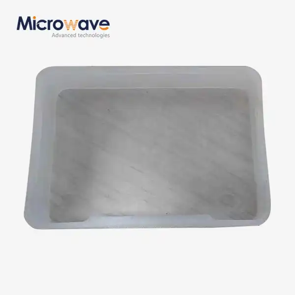
Waveguide systems are the best choice when high power, low loss, and wide stopband rejection are all needed at the same time. Metal waveguide design is very strong mechanically, so it can handle shaking and changes in temperature in defense and aircraft systems where dependability is essential. Hermetically sealed versions keep their performance in vacuum or pressure conditions by stopping moisture from getting in and breaking down the multipactor.
Power Level Considerations
When designing low-power waveguide filters for measurement or receiver security, they focus on having low insertion loss and tight VSWR requirements, usually below 1.2:1 across the working band. High-power versions have features built in to keep the voltage from dropping: rounded corners inside spread out electric field concentrations, and adding SF6 or dry nitrogen gas raises the breakdown limits. To make sure that the device works reliably at certain power levels without arcing, calculations based on Paschen curve analysis are used to decide how to treat the surface and how far apart the gaps should be.
Procurement Insight: How to Buy the Right Waveguide Low Pass Filter?
In order to get something, you have to balance scientific requirements with real issues like lead time, cost, and source skills. Standard stock items are easy to find and can be delivered quickly, but they might not exactly meet the needs of your system. Custom designs, on the other hand, improve performance but take longer to build.
How to Choose the Correct Waveguide Low Pass Filter for Your Needs requires careful attention to specific parameters. Procurement teams should define frequency range requirements with precision, including passband limits, cutoff frequency, and stopband attenuation levels at certain harmonic frequencies. Power handling requirements need to take into account both peak power during pulsed operation and continuous average power. This is because pulsed operation and continuous average power put different stresses on temperature and voltage. The passband region's VSWR standards have a direct effect on how well the system matches and transfers power.
Critical Specification Parameters
Standards for mechanical interfaces need to be carefully thought out. EIA flange codes (WR-90, WR-137, WR-284, etc.) make sure that new waveguides and radio lines will work with the old ones. For some uses, you need special pressure windows, vacuum flanges, or thermal cooling connections, which make things more difficult and cost more.
Supplier Landscape
Well-known companies like K&L Microwave, Pasternack, and API Technologies keep huge collections of standard waveguide parts with clear descriptions and quick delivery. When needs match up with current product lines, these sellers do a good job. Custom waveguide assembly projects are handled by companies like Advanced Microwave Technologies Co., Ltd, which has been making products for 20 years and is ISO 9001 certified. Their engineering teams work directly with sourcing experts to turn system-level needs into plans that can be made.
For systems that use more than one source, distributor networks make it easier to get supplies, but they may cause lead times to vary. Working directly with makers speeds up technical conversations during design review and lowers the chance of misunderstandings. Digital buying platforms make it easy to get quotes quickly, but sellers must be carefully checked to make sure they keep the quality standards and tracking paperwork needed for defense and aircraft uses.
Lead Time and Customization
Standard items usually get shipped within two to four weeks. Custom designs, on the other hand, take six to twelve weeks to complete, which includes electromagnetic modeling, sample manufacturing, and testing to make sure they work. Rush classes can shorten plans, but they usually cost more. Getting suppliers involved early on in the system design process lets work be done in parallel, which keeps schedule effects to a minimum.
Unlocking Performance Benefits: Advantages and Optimization Strategies
When properly implemented, the technical benefits of Waveguide Low Pass Filters directly lead to measured improvements in the system. Knowing these benefits helps you make decisions about which components to use and leads your efforts to make the system work better when it's being put together.
Very little insertion loss keeps the efficiency of the sender and the sensitivity of the receiver. When sending several kilowatts through satellite launch systems, even 0.1 dB of insertion loss means that hundreds of watts are lost as heat and don't reach the satellite. The absorption losses of waveguide filters are as low as 0.05 dB thanks to their optimized internal shapes and high-conductivity surface finishes. This efficiency benefit gets bigger in systems with a lot of components that are linked to each other.
Key Performance Attributes
Broad stopband rejection stops harmonics across many octaves without the need for multiple stacked filter stages. A well-designed waveguide low pass filter can attenuate by 60 dB or more at the second and third harmonic frequencies. This gets rid of unwanted sounds that lower spectral occupancy. When compared to methods that need multiple cascaded filters, this single-stage harmonic reduction makes the system design easier to understand.
Better power handling lets you connect directly to high-power emitters without using attenuators or isolators first. Filters with a constant power rating of 10 kW or a peak power rating of 100 kW fit perfectly after klystron amps or traveling-wave tubes in radar and radio uses. Waveguide structures naturally handle high levels of power that would kill other technologies because of their thermal mass and ability to dissipate heat.
Integration Best Practices
These parts are strong enough to withstand shocks, vibrations, and changes in temperature, so they can be used in outdoor setups and mobile platforms that are exposed to these conditions. In marine and aircraft settings, hermetically sealed units keep the pressure inside and stop pollution. Some designs have fitting rings and cooling fins that are built in. This makes mechanical integration easier and better manages heat.
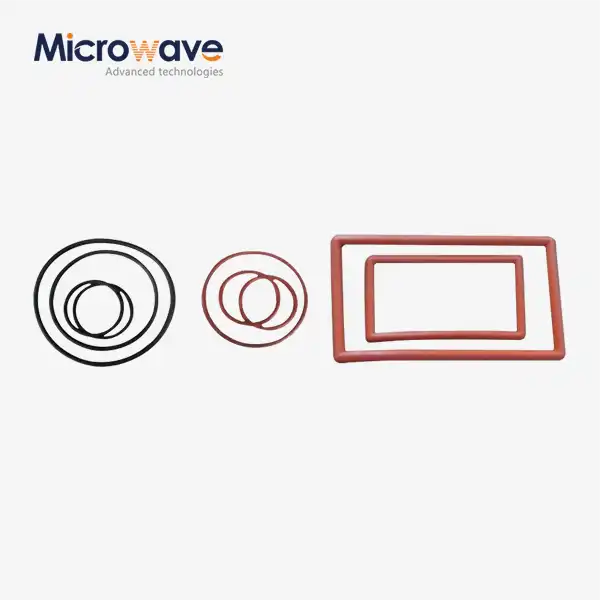
When you torque the flange properly, you protect the RF seal and stop leaking, which lowers VSWR. Manufacturers give force numbers that are usually between 40 and 100 inch-pounds, but this depends on the size of the joint. When you use measured torque tools and tighten in a star design, the binding force is spread out evenly. Low-impedance radio waves can flow through the contact when silver-plated gaskets or indium wire covers are placed between the flanges.
Real-World Implementation Results
When putting filters on radio lines or movable platforms, system designers need to think about how the weight and center of gravity will affect the system. When waveguide connections are properly supported mechanically, stress doesn't build up and cause wear breakdowns during working shaking. Long-term dependability is maintained by managing cable route and bend radius for any built-in temperature or pressure sensors.
A defense contractor who was updating coastal surveillance radar systems added custom waveguide low pass filters to the emitter chains that were already there. The 65 dB harmonic rejection got rid of interference with nearby communication bands, so the radar met all the rules without having to lower its main power. The filters were put into use five years ago and were able to handle 5 kW of power constantly at temperatures ranging from -40°C to +60°C without any problems.
As part of updating the system, workers at satellite ground stations swapped out old coaxial filters for waveguide filters. The 0.08 dB improvement in insertion loss brought back 180 watts of transmitting power, which meant better uplink cushion in rain-fade conditions. Field breakdowns caused by temperature cycling and moisture getting into coaxial designs were no longer possible because of the strong mechanical construction.
Conclusion
If you need high power, low loss, and spectral clarity all at the same time, Waveguide Low Pass Filters will give you the best results. Their electromagnetic principles, which come from waveguide physics, make them better than other filter technologies. Precise manufacturing and material science turn theoretical ideas into hardware that works well. Knowing the basic technical terms, how different products work, and how to buy them gives engineers and buying professionals the power to make smart choices that improve system performance. They play an important part in challenging microwave systems, as shown by their track record in radar, satellite transmission, and study.
FAQ
Q1: What are the most important things that affect the frequency response of a waveguide low pass filter?
When it comes to frequency reaction, internal measurement consistency, and material conductivity are the most important factors for a Waveguide Low Pass Filter. To get the desired cutoff frequencies and passband flatness, the iris opening measurements, hollow depths, and ridge spacing must all be kept to within microns. The choice of base metal and coating material affects the surface conductivity, which in turn affects insertion loss. Silver plating gives the best performance.
Q2: How do the insertion loss specs of waveguide and coaxial low pass filters compare to each other?
When it comes to passband areas, waveguide designs usually have insertion losses of 0.05-0.10 dB, while coaxial designs have losses of 0.3-0.5 dB at similar frequencies. This is because there aren't any lossy insulating materials at the sides of the waveguide, so there is less current density there. At higher frequencies, where cable losses rise quickly, the difference is more noticeable.
Q3: What lead times should procurement teams expect for custom waveguide filter development?
It takes eight to twelve weeks for custom designs to go from finalizing the specifications to delivering the prototype. This time includes electromagnetic simulation validation, precision cutting, finishing processes, and full S-parameter testing. Depending on the size of the order, production numbers take an extra four to six weeks. Early involvement in the system planning stages allows for parallel development that has the least amount of effect on schedules.
Partner with ADM for Your Waveguide Low Pass Filter Solutions
Advanced Microwave Technologies Co., Ltd has been making accurate waveguide components for over twenty years and has quality control ISO 9001 certification for the defense, military, and satellite communication industries. Our engineers work directly with sourcing specialists and system builders to create custom Waveguide Low Pass Filter solutions that meet exact standards for frequency response, power handling, and environmental concerns. We are ready to help you with your most difficult projects because we can measure up to 110 GHz and have a history of providing mission-critical RF components. Our efficient development process, reasonable pricing, and reliable delivery make ADM your go-to waveguide low pass filter maker, whether you need standard setups or custom-engineered designs. Email craig@admicrowave.com right away to talk about your specific needs, get technical datasheets, or get full quotes for your future buying projects.
References
1. Collin, R.E., Foundations for Microwave Engineering, Second Edition, IEEE Press, 2001.
2. Matthaei, G.L., Young, L., and Jones, E.M.T., Microwave Filters, Impedance-Matching Networks, and Coupling Structures, Artech House, 1980.
3. Pozar, D.M., Microwave Engineering, Fourth Edition, John Wiley & Sons, 2012.
4. Bornemann, J. and Vahldieck, R., "Characterization of a Class of Waveguide Discontinuities Using a Modified TE10 Mode Approach", IEEE Transactions on Microwave Theory and Techniques, 1990.
5. Levy, R., "Filters for Satellite Communication Systems", IEEE Transactions on Microwave Theory and Techniques, 1995.
6. Snyder, R.V., "Practical Aspects of Microwave Filter Development", IEEE Microwave Magazine, 2007.