Custom WG Bandpass Filter Solutions for Advanced Projects
When mission-critical RF systems demand uncompromising performance, custom WG Bandpass Filter solutions emerge as the cornerstone of signal integrity. These precision-engineered waveguide components offer superior frequency selectivity, minimal insertion loss, and exceptional power handling capabilities that standard filtering technologies simply cannot match. For defense contractors, satellite integrators, and telecommunications system builders, understanding how to specify, procure, and deploy customized waveguide bandpass filters can mean the difference between system success and costly redesigns.
Understanding WG Bandpass Filters and Their Core Principles
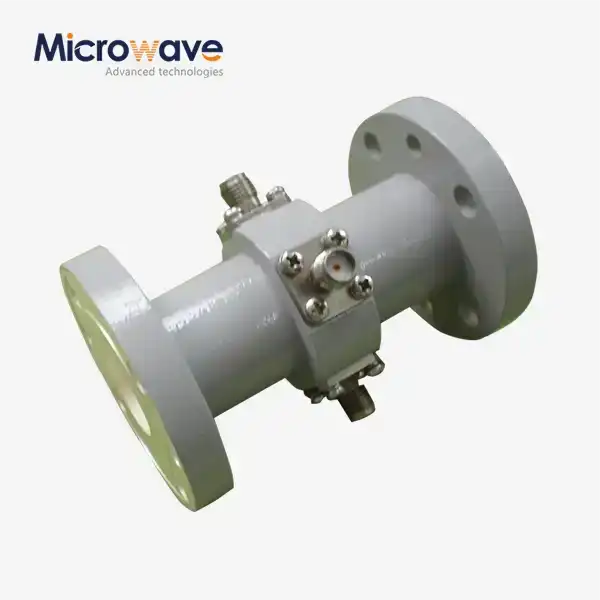
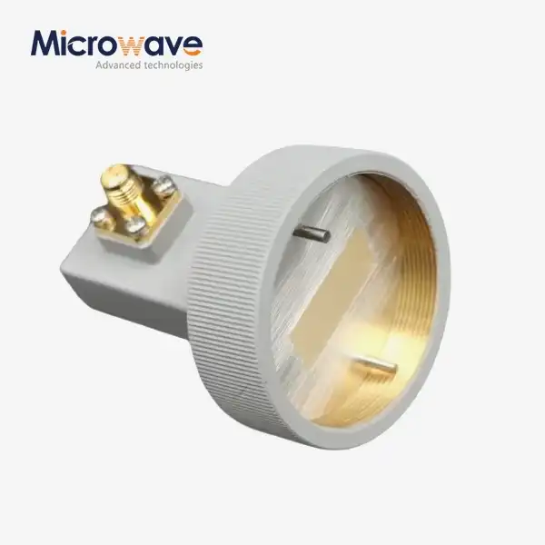
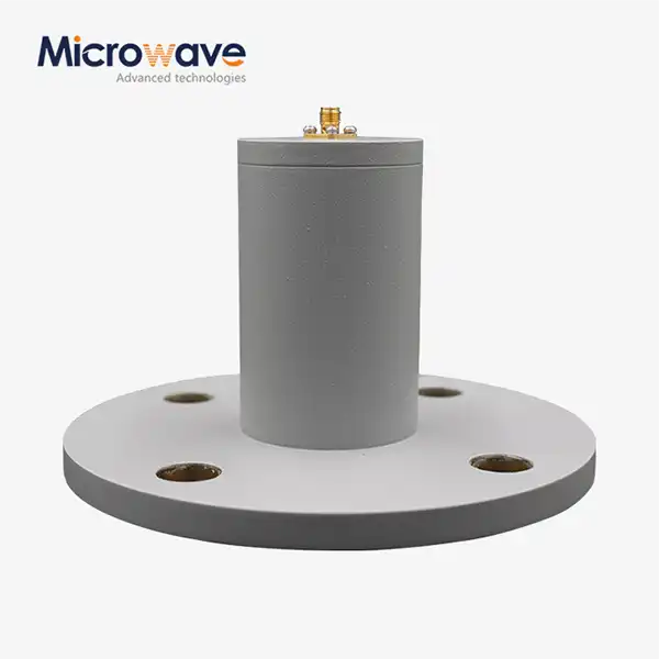
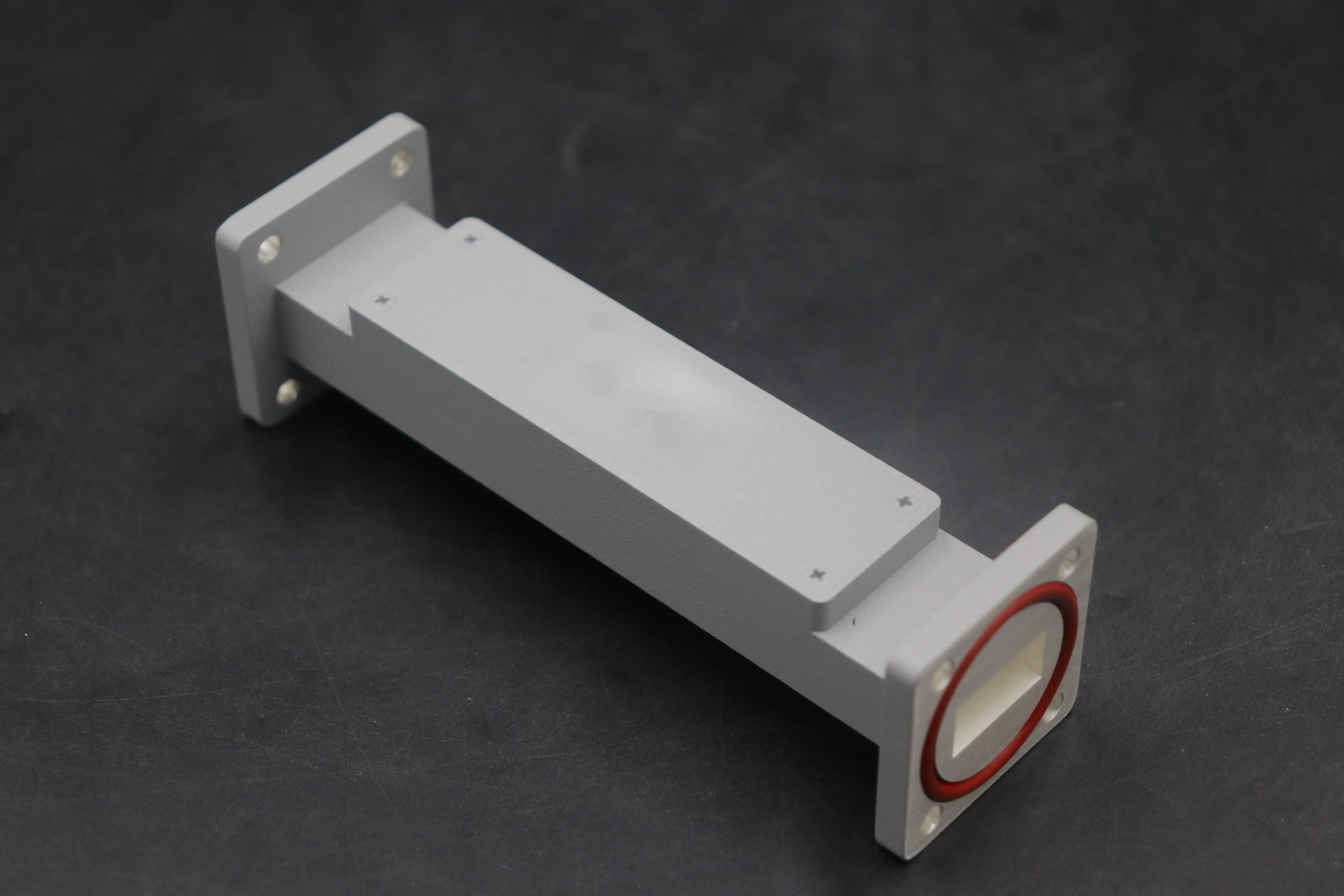
In high-power, high-frequency settings, WG Bandpass Filters are a sophisticated way to choose the frequency. In contrast to their coaxial or planar counterparts, these parts use hollow metal structures that guide electromagnetic waves with incredibly low loss. The basic idea behind how it works is based on resonant cavities that are carefully sized so that they only respond to certain frequency bands and ignore other signals.
Construction and Design Elements
Resonant Cavity Architecture: The filter is made up of several connected parts that have all been cut to exact specifications. By resonating at the desired center frequency, these cavities exhibit passband characteristics. Bandwidth is set by how well the sections are coupled to each other, and selectivity steepness is determined by the number of sections.
Material Selection Impact: The structure is made of high-conductivity metals like aluminum 6061, which are often strengthened with silver plating to reduce skin-effect losses. In aircraft uses that need high thermal stability, Invar parts may be needed to stop frequency drift caused by expansion.
Electromagnetic modeling tools like HFSS and CST Microwave Studio are used in the design process. This lets engineers guess how well the design will work before they start making it. To meet the requirements, these simulations take into account coupling coefficients, unloaded Q-factors, and the distance between resonators. We at Advanced Microwave Technologies Co., Ltd use our 24m Microwave Darkroom and testing tools that can go up to 110 GHz to make sure that plans work across the whole operational range.
Comparison with Alternative Technologies
In some situations, WG Bandpass Filters are clearly better than microstrip, LC lumped-element, and dielectric resonator filters. Microstrip screens lose power through radiation and can't handle more than 10 watts of power, so they can't be used in transmitters. LC filters are small, but they have problems with temperature stability and Q-factor limits that make them less selective. Dielectric resonator filters fill in some gaps, but they can still be damaged by sudden changes in temperature or force.
When insertion loss has a direct effect on link budgets, like in high-power radar transmitters, satellite earth stations, and millimeter-wave backhaul links, the waveguide method works best. A normal X-band WG Bandpass Filter has an insertion loss of less than 0.4 dB and an out-of-band rejection of more than 80 dB. Other designs can't match this performance at the same power levels.
Choosing the Right WG Bandpass Filter for Your Project
Decisions about what to buy depend on how well the technical needs are outlined and how they match up with the working limitations. Engineers have to turn system-level requirements into WG Bandpass Filter factors while taking differences in the environment and the need for long-term dependability into account.
Defining Application Criteria
Frequency Range Specifications: Satellite C-band systems (3.7–4.2 GHz uplink, 5.925–6.425 GHz downlink) need filters with precise channel isolation to stop interference from other satellites. For 256-QAM modulation schemes to work, millimeter-wave 5G backhaul in the E-band (71–76 GHz, 81–86 GHz) needs filters that keep the spectrum pure.
Bandwidth and Shape Factor: Narrow-bandwidth filters (fractional bandwidth less than 5%) work well for radar pulse compression and channelized receivers. When group delay flatness is important to keep the signal integrity, wide-bandwidth designs (10–20% fractional bandwidth) allow broadband communication lines.
Insertion Loss Tolerance: In order to keep the system noise figure low, receiver front-end filters need to keep insertion loss below 0.5 dB. If power handling and noise avoidance are the most important things, transmitter filters can handle a little more loss (0.8 to 1.2 dB).
Comparative Manufacturer Assessment
When you're buying something, you have to think carefully about the wait times. For custom designs, they can take up to six weeks because of the number of simulations, the accuracy of CNC machining, and the need for human tuning. Our engineering team at ADM speeds up this process by offering rapid prototyping services and using our advanced measurement facilities to validate designs at the same time.
A study of the market shows that different suppliers have different positions. Well-known companies like Pasternack and Mini-Circuits sell stock items that can be delivered quickly but can't be changed much. Specialized houses offer in-depth tech work for specific needs. ADM stands out because it has combined design and production processes, ISO 9001:2015 quality systems, and more than 20 years of experience making radio components for the defense, aerospace, and telecoms industries around the world.
Advantages and Applications of Custom WG Bandpass Filters
Customized WG Bandpass Filter solutions improve performance in a way that directly benefits the whole system. Custom designs are more flexible from an engineering point of view, which lets them be optimized for specific operating situations that standard components can't handle.
Performance Characteristics
High Q-Factor and Selectivity: Q values above 5,000 when not loaded allow for very steep transition bands, which are needed to block adjacent channels in crowded spectral areas. In SATCOM earth stations, where multiple carriers must work together without interfering with each other, this trait is very useful.
Power Handling Capability: Since there are no dielectric materials or center conductors, there are no thermal breakdown mechanisms. When used in radar, custom WG Bandpass Filters can handle steady wave power of kilowatts and peak pulse power of megawatts without any problems with multiplication or arcing.
Environmental Robustness: Custom designs can include temperature-compensating structures, pressure windows for vacuum operation, and conformal coatings for use in marine settings. These changes make sure that the performance stays the same from -40°C to +85°C.
Future-Proofing Investment
These benefits can be seen in real-world deployments. For a Ka-band earth station project, the filters had to have a 500 MHz frequency centered at 20 GHz, an insertion loss of less than 0.6 dB, and be able to work in a seaside area with salt fog. Our unique silver-plated aluminum design with hermetic seals met all requirements for five years of field use. In the same way, a naval fire-control radar application needed X-band filters that could withstand MIL-STD-810 shock tests and block harmonics by 90 dB to keep the receiver chains safe.
Custom filters are made with enough room for future system improvements. Overly narrow rejection bands keep new services given by regulatory bodies from interfering. With modular flange connections, you can change the filter without having to rethink the whole RF chain. These strategic factors protect capital investment and extend the lifetime of a system.
Procurement Process: How to Buy Custom WG Bandpass Filters
A thorough set of specifications that includes both technical needs and operational context is the first step to a successful procurement of a WG Bandpass Filter. Iteration cycles and misunderstandings that cost a lot of money can be avoided if procurement teams and tech sources can talk to each other clearly.
Specification Development
Technical datasheets should list the center frequency, passband bandwidth (3 dB points), insertion loss budget, return loss goals (usually VSWR < 1.3:1), and the offset frequencies for which out-of-band rejection is needed. The operating temperature range, storage limits, humidity exposure, vibration profiles, and any relevant military standards must all be included in the environmental specs. Interface standards describe the types of flanges (UG-series, CPR, or custom), the direction of the ports, and how they are to be mounted.
Pricing and Budget Considerations
By getting quotes from several suppliers, you can compare costs and benefits. At ADM, our team provides thorough ideas that include electromagnetic modeling results, mechanical drawings, and plans for validation tests. Customers are encouraged to involve our engineering staff early on in the idea creation process so that specifications can be optimized for cost-effectiveness and ease of production.
WG Bandpass Filter prices depend on how complicated the design is, the frequency range it covers, and how many are made. X-band filters with a middling bandwidth usually cost between $1,200 and $3,500 for a single unit. If you buy more than 10 pieces, you can get big savings. Millimeter-wave devices above 40 GHz are more expensive because they have to be made to tighter standards and meet specific measurement needs. Custom frequency adjustment or rare materials raise the base price by 15 to 30 percent.
When making a budget, you should include money for qualification testing, which could include third-party approval if quality systems need it. Our ISO 9001 certification and strict internal testing methods give you trust in the work we do, which lowers the costs of confirmation further down the line.
After-Sales Support and Documentation
Every delivery comes with detailed datasheets that list the measured S-parameters, dimensional outlines, and handling instructions. We keep track of things by serializing them and keeping inspection records that meet AS9100 aircraft standards. Technical support doesn't stop with delivery; our engineers are also ready to help with integration problems and give advice on how to make the system run more efficiently.
OEM partnerships benefit from working together on a regular basis, which includes updating designs to make them easier to manufacture and using better technology. Because of these connections, just-in-time shipping is possible, which works with production plans. This cuts down on the costs of keeping inventory and makes sure that parts are always available.
Technical Insights: Enhancing WG Bandpass Filter Performance
To get the best performance out of a WG Bandpass Filter, engineers need to understand the trade-offs and use advanced tuning methods. Specification limits can be met through both simulations during the design phase and tuning after the fabrication process.
Simulation and Modeling Best Practices
Software for electromagnetic simulation lets you make virtual prototypes, which speeds up the development process. For simulations to be accurate, they need to have correct descriptions of material properties like conductivity, loss tangent, and thermal expansion factors. By making the mesh finer around the coupling irises and tuning elements, field concentrations that control insertion loss and power handling can be captured. Before going to fabrication, convergence analysis makes sure that the accuracy of the answer meets the design requirements.
To predict the effects of manufacturing variation, our engineering workflow includes tolerance analysis. Monte Carlo simulations with realistic machining tolerances show how sensitive something is to errors in dimensions. This helps set inspection priorities and fine-tune the placement of elements.
Common Design Challenges
Insertion Loss Optimization: Designers have to find a way to balance low loss with the need for high capacity. Adding more resonators makes the selectivity better, but it also causes more dissipative losses. This trade-off can be lessened by using high-conductivity plating and better connection shapes in a smart way.
Spurious Mode Suppression: WG Bandpass Filter designs allow for multiple propagation modes at higher frequencies, which create passbands that aren't needed. Adding mode-suppression features like ridged sections or absorptive loads makes the usable frequency range bigger while keeping the rejection properties clean.
Temperature Stability: As the temperature rises or falls, the resonant frequencies move, which lowers performance across all operating temperature ranges. Bimetallic tuning mechanisms or computer-optimized cavity shapes make up for expected temperature drift, keeping specs the same in all kinds of environments.
New trends in integration put together small systems that have WG Bandpass Filters, solid-state amplification, and antenna lines. These units can do more than one thing. They cut down on interconnect losses and make system design easier. We can help with these complex integration projects because we have experience designing feed networks and can use our customization tools and testing infrastructure to make sure that complex RF systems work.
Conclusion
Custom WG Bandpass Filters are still needed for high-tech RF systems that can't skimp on performance. Properly designed waveguide solutions are used in satellite communications, defense radar, and next-generation wireless infrastructure because they are better at handling power, being selective, and lasting in harsh environments. For implementation to go smoothly, specifications must be carefully thought out, suppliers must be carefully chosen, and expert teams must continue to work together. Companies that buy custom filter solutions get a competitive edge because their systems work better, are less likely to be affected by interference, and are reliable over time, which saves their investments.
Frequently Asked Questions
Why choose waveguide over coaxial bandpass filters?
WG Bandpass Filter designs don't need the dielectric materials and center conductors that coaxial designs do. This makes insertion loss at microwave frequencies much smaller. This design lets power be measured in kilowatts instead of watts, which is very important for broadcast uses. Above 10 GHz, cable losses are too high to use, but waveguides stay efficient.
How does temperature affect filter performance?
When metal expands with temperature, resonant frequencies move down by about 20 to 50 ppm per degree Celsius in a normal aluminum structure. Invar alloys or compensation structures are used in high-stability applications to stop this drift and keep the center frequency within tight ranges across all operational temperature ranges. Thermal analysis is used in our designs to predict and reduce temperature reactivity.
What lead times should I expect for custom orders?
It usually takes 4 to 6 weeks from the time the specifications are approved until the custom WG Bandpass Filter project is delivered. This timeline includes electromagnetic simulation and optimization, precision CNC machining with tolerances of less than a thousandth of an inch, silver plating application, and manual tuning with validation from a vector network analyzer. If you need something quickly, rush services can shorten your wait time, but faster fabrication may cost more.
Can these filters be returned after deployment?
Most designs have adjustment screws that let you make small changes to the frequency while the system is being installed. But field tuning without accurate network tester gear could hurt the performance of return loss and rejection. We suggest that qualified people do re-tuning in the lab to keep specs and keep precision parts from getting damaged by mistake.
Partner with ADM for Precision-Engineered WG Bandpass Filter Solutions
Advanced Microwave Technologies Co., Ltd has state-of-the-art equipment and more than 20 years of experience making microwave products. They can make unique WG Bandpass Filters that go above and beyond what is required. Our ISO 9001:2015-certified processes, 24m anechoic chamber, and ability to measure up to 110 GHz make sure that your filters work perfectly in the toughest situations. If you need a WG Bandpass Filter supplier for either making a prototype or a lot of them, our engineering team can help you from the idea stage all the way through deployment. Get in touch with craig@admicrowave.com right away to talk about your project needs and find out how our customization options, rapid prototyping services, and low prices make us a great deal for defense, telecommunications, and satellite uses around the world.
References
1. Matthaei, G.L., Young, L., and Jones, E.M.T. Microwave Filters, Impedance-Matching Networks, and Coupling Structures. Artech House, 1980.
2. Cameron, R.J., Kudsia, C.M., and Mansour, R.R. Microwave Filters for Communication Systems: Fundamentals, Design, and Applications. Wiley-IEEE Press, 2018.
3. Pozar, D.M. Microwave Engineering, 4th Edition. John Wiley & Sons, 2011.
4. Levy, R. "Filters for Satellite Communications." IEEE Transactions on Microwave Theory and Techniques, Vol. 32, No. 9, 1984.
5. Hunter, I.C. Theory and Design of Microwave Filters. Institution of Engineering and Technology, 2001.
6. Rhodes, J.D. Theory of Electrical Filters. John Wiley & Sons, 1976.