Custom Crossguide Coupler Manufacturing Considerations
When sourcing precision RF components for mission-critical applications, understanding the nuances of crossguide coupler manufacturing becomes paramount. A crossguide coupler is a specialized waveguide device that samples microwave energy from one waveguide path and directs it to another, enabling signal monitoring, power distribution, and system diagnostics without disrupting primary signal flow. Manufacturing custom crossguide couplers requires meticulous attention to mechanical precision, material selection, and electromagnetic performance validation—factors that directly influence long-term reliability in radar, satellite communication, and defense systems where signal integrity cannot be compromised.
Understanding Crossguide Couplers: Fundamentals and Specifications
Operating Principles and System Significance
Crossguide couplers work by controlling the electromagnetic coupling between two waveguide channels that are not parallel to each other. This orthogonal geometry makes it possible to sample power accurately with little effect on the mainline gearbox. The coupling mechanism depends on carefully placed holes or slots that let controlled energy flow based on how the electromagnetic field is spread out in the waveguide structure.
In radar systems, these parts let the transmitter be watched without affecting the signal. They are used by satellite ground sites to send signals to various receivers at the same time. The perpendicular arrangement is better at isolating signals than inline directional couplers. This makes crossguide designs very useful when space is limited or when the shape needs to be flexible.
Essential Technical Specifications
Frequency range determines operating bandwidth based on the frequency range, which can cover a single band or multiple bands from L-band to Ka-band. Coupling value tells you the ratio of the recorded power to the stream power, usually between 10 and 40 dB depending on the application. Insertion loss is a way to measure how weak a signal is in the primary path, where values below 0.3 dB are possible with precise manufacturing. Directivity tells you how well the coupler can tell the difference between forward and reverse power flow, with high-performance units having a directivity of 30 dB or more. Power handling capacity takes into account voltage breakdown limits and thermal management, which are very important for radar and communication transmitters that use a lot of power.
Common Types and Applications
When compared to single-hole designs, multi-hole designs have a wider bandwidth and better directivity because they use multiple connection holes spread out along the length of the waveguide. Branch-line versions use quarter-wave stub links to get the best frequency performance. Depending on the material used and the shape of the aperture, the coupler can be used for either narrowband precision measurements or wideband monitoring. Defence companies often need ruggedised versions that are hermetically sealed and keep the temperature stable. On the other hand, research institutions may want coupling values that can be changed to allow for more lab freedom.
Critical Manufacturing Considerations for Custom Crossguide Couplers
Defining Technical Requirements
Before the parts are made, engineering teams have to turn system-level needs into exact part specifications. An operating environment analysis looks at the highs and lows of temperature, the patterns of vibration, and the amount of humidity that an installation would normally be exposed to in the air, on a ship, or on the ground. Performance goals should include limits on acceptable insertion loss, required directivity across the operating band, and VSWR that makes sure the system's impedance matches that of its parts.
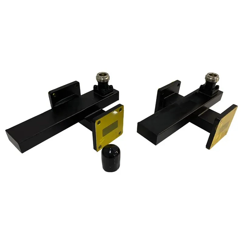

During this part of the definition, we at Advanced Microwave Technologies Co., Ltd. work closely with procurement experts and use our more than 20 years of experience to spot early on any possible design problems for custom crossguide couplers. Our technical team looks at system block diagrams and interface specs to figure out the best coupling values and frequency reactions that balance performance with ease of production.
Material Selection and Surface Treatment
The choice of material has a big impact on both the RF performance and the mechanical longevity. When we make custom crossguide couplers, these are the main choices we look at:
- Copper alloys are great for prototypes and small to medium-scale production because they are good at conducting electricity and can be machined easily. Aluminum is lighter than other materials used in aerospace applications, and it still conducts electricity well when it is properly plated. Stainless steel is better at resisting corrosion in marine and harsh environments, but it needs to be machined in a certain way.
- Surface cleaning makes parts last longer and keeps their electrical properties. Silver plating lowers surface resistance and makes it easier to handle power, and gold plating stops rusting when the item is stored for a long time or used in wet conditions. Passivation processes keep the surface of stainless steel safe without affecting its ability to conduct radio waves. Electroplating is done in a controlled environment at our factory, and the thickness is checked with X-ray fluorescence to make sure that all the complex internal shapes are covered evenly.
- When you use the right base materials and the best surface processes, they have a direct effect on signal loss and long-term security. For parts going to satellite ground stations, they need to be treated in a way that keeps them working for years without losing any performance. On the other hand, lab instruments may put cost-effectiveness over extreme environmental resilience.
Manufacturing Tolerances and Quality Control
To get the desired electrostatic performance, you need to be very precise with the mechanics. Our building has CNC machining centers that keep positional accuracy within 0.025 mm. This makes sure that coupling holes line up properly and waveguide dimensions meet strict requirements. When millimetre waves are sent at frequencies above 30 GHz, even small changes in dimensions can cause resonant frequencies to shift or directivity to decrease.
Before shipping, quality control tests make sure that all performance parameters are correct. The measurements made by a network analyzer get all of the S-parameter data over the frequency range that was given. This checks for insertion loss, coupling accuracy, directivity, and return loss. We keep track of measurement errors and give calibrated test reports that can be traced back to national standards. This meets the ISO 9001:2015 requirements that procurement teams are asking for more and more. Temperature cycles and mechanical stress testing find ways that parts might break before they are put to use in the field.
Production Scalability and Lead Times
To get the best balance between prototype flexibility and production efficiency, manufacturing processes need to be able to change. Our minimum order quantity allows for single-unit prototypes for research and development projects while still allowing for production runs of several hundred units when designs are ready for full-scale use. Lead times depend on how complicated the design is. For example, normal X-band designs usually ship within four weeks, but custom Ka-band kits with unique features may need eight to ten weeks to be fully built and tested.
We keep a strategic stockpile of raw materials for popular waveguide sizes and coupling setups. This speeds up the process for repeat orders. By working together on forecasts with regular customers, output schedules can be made that work with their system integration schedules. When circumstances call for faster delivery, rush orders can be accommodated, but better resource allocation across multiple projects is possible with advance communication.
Crossguide Coupler Performance Optimization: Comparing Solutions
Performance Metrics Analysis
When application needs go beyond what standard components can do, custom crossguide coupler designs offer measurable advantages over off-the-shelf options. Even though 0.1 to 0.2 dB increases in insertion loss may not seem like much, they add up in multi-stage RF chains and affect signal strength and system sensitivity. Increasing the directivity from 25 dB to 35 dB makes it possible for automatic test systems to measure power more accurately and find faults more quickly.
Bandwidth optimisation is another important way to set yourself apart. Standard couplers usually cover octave ranges with smoothness that is good enough but not great. It is possible to get coupling flatness within ±0.5 dB across 40% or more of the fractional bandwidth with custom aperture designs and compensated geometries. This meets the strict requirements for wideband radar and electronic warfare applications where uniform response stops measurement errors.
Cost Versus Performance Trade-Offs
When buying something, people have to weigh the benefits of customization against the limits of their income. Standard waveguide components are easy to find and don't cost as much per unit, so they are a good choice when the requirements match the options that are available. Custom development takes time from engineers, money to buy tools, and multiple iterations of prototypes. These things raise the original costs but pay off in the long run by improving speed and making system-level integration easier.
Our team gives clear cost breakdowns that split one-time planning fees from unit production costs, which lets you make accurate budgets for the whole lifecycle. When more than 50 to 100 units are made, amortised tooling costs go down, and custom solutions often become as cheap as standard alternatives while performing better. Managing risk with tried-and-true designs and manufacturing methods lowers the total cost of ownership compared to making changes in the field to standard parts that don't work right.
Design Methodologies for High Performance
To get low-loss and high-directivity properties, you need to carefully model the electromagnetic field and make small changes over and over again. We use full-wave modelling tools to look at how fields are distributed in coupling regions and find the best aperture shapes and positions before making real samples. Multi-objective optimization algorithms find the best balance between different needs. For example, tighter coupling raises sampled power but could lower mainline insertion loss if the aperture geometry makes too many discontinuities.
Changes to the manufacturing process improve performance even more. Precision electroforming makes coupling openings with controlled curves and smooth edges, which reduces the amount of field intensity in one area that causes loss. When compared to bolted systems, integrated waveguide flanges get rid of interface gaps. This makes electrical contact better and lowers passive intermodulation products in high-power situations. These improvements turn basic designs into optimised ones that make system-level signal fidelity much better.
Procurement and Supplier Selection Guide for Custom Crossguide Couplers
Evaluating Manufacturer Capabilities
To choose the right cross-guide coupler manufacturing partner, you need to look at more than just price quotes. Objective proof of process development is provided by quality certificates. For example, our ISO 9001:2015 and RoHS compliance show that we are committed to consistent quality and environmental responsibility. OEM capabilities show the ability to add customer-specific features, logos, and document types that make it easier to integrate into bigger systems.
When customization goes beyond catalogue variations, technical depth is very important. Our engineering team is very good at designing electric systems, making machines work well, and making sure that things are made precisely. Look at the profiles of different suppliers to make sure they have experience with frequency ranges, power levels, and environmental needs that are similar to yours. Ask for sample test reports to check the accuracy of the measurements and the completeness of the documentation.
Pricing Transparency and Support Services
Suppliers you can trust give you detailed quotes that break down the costs of materials, labour, testing, and packaging. For precision RF parts, the warranty should cover both problems with the way the part was made and performance loss. It should last for at least one to two years. After-sales support is what sets reputable makers apart from order-takers. Having access to application experts who can help with questions about integration, troubleshooting, and performance optimization is a big plus that goes beyond the component itself.
Ordering Process and Logistics
Complete recording of requirements is the first step to efficient buying. The frequency range, coupling value with tolerance, power handling, interface flanges, and environmental conditions should all be written on specification sheets. By telling our engineers about the system's application type, nearby components, and integration limitations, you help them find the best solutions and spot any possible compatibility problems before production starts.
Early engagement helps with lead time management. Having preliminary talks during the system design stages lets manufacturers plan their work in a way that matches the arrival of parts with the integration dates. Different project schedules can be met by a variety of shipping choices, ranging from standard ground freight for regular orders to fast air transport when time is of the essence. Custom packaging solutions use foam inserts and moisture barriers that are suitable for international shipping or long-term storage to protect sensitive RF surfaces, including crossguide coupler components, during transit.
Conclusion
To make unique crossguide couplers, you need technical know-how, precise manufacturing, and strict quality control that goes beyond making standard parts. Every decision made during the manufacturing process affects the final performance and long-term dependability. This includes defining the requirements at the beginning and choosing the materials, machining them, and testing them thoroughly. Advanced Microwave Technologies Co., Ltd. has been working on this problem for more than 20 years and has provided answers that meet strict requirements for study, defence, space, and satellite communication. Our ISO-certified processes, state-of-the-art test facilities that go up to 110 GHz, and dedication to open communication make us a reliable manufacturing partner for procurement teams looking for custom RF solutions that work well in mission-critical systems.
FAQ
1. What lead time should I expect for custom crossguide coupler orders?
Standard X-band and Ku-band designs usually ship four weeks after the order is confirmed and the requirements are finalized. It could take eight to ten weeks to fully engineer, build, and test complex custom crossguide coupler designs that need special materials, unique coupling configurations, or millimeter-wave frequencies. When we quote, we include thorough production schedules and stay in touch regularly during production. If project deadlines require faster delivery, we also offer expedited choices.
2. How do I determine the appropriate coupling value for my application?
When choosing a coupling value, measurement accuracy and core entry loss are weighed against each other. When coupling is tighter (lower dB values like 10 or 20 dB), sampled signals are better for monitoring, but primary path loss goes up. When coupling is looser (30 to 40 dB), mainline effect is lessened but more sensitive detection equipment is needed. Our application engineers look at your system's structure, signal levels, and monitoring needs to give you the best coupling values that meet your performance goals without sacrificing too much.
Partner with ADM for Your Custom Crossguide Coupler Requirements
Advanced Microwave Technologies Co., Ltd. is ready to turn your technical needs into solutions that are precisely made. As an experienced crossguide coupler maker, we offer advanced measurement tools, such as our 24m Microwave Darkroom for testing up to 110 GHz, along with OEM services that are flexible enough to handle both small-scale production and prototype development. Our expert team works closely with procurement engineers to make sure that plans are the best they can be in terms of performance, dependability, and cost. Contact craig@admicrowave.com right away to talk about your unique application needs and find out how our manufacturing experience gives you a competitive edge through high-quality parts and quick customer service.
References
1. Pozar, David M. Microwave Engineering, Fourth Edition. Hoboken: John Wiley & Sons, 2012.
2. Matthaei, George L., Leo Young, and E.M.T. Jones. Microwave Filters, Impedance-Matching Networks, and Coupling Structures. Dedham: Artech House, 1980.
3. Saad, Theodor. Microwave Engineers' Handbook, Volume Two. Dedham: Artech House, 1971.
4. Ishii, Thomas Koryu. Handbook of Microwave Technology: Components and Devices, Volume 1. San Diego: Academic Press, 1995.
5. IEEE Standard 145-2013. IEEE Standard for Definitions of Terms for Antennas. New York: Institute of Electrical and Electronics Engineers, 2014.
6. Balanis, Constantine A. Advanced Engineering Electromagnetics, Second Edition. Hoboken: John Wiley & Sons, 2012.