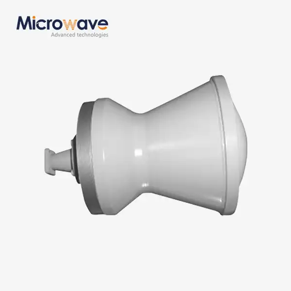
Horn Lens Antenna Design Factors Affecting Signal Quality
When evaluating horn lens antenna performance in mission-critical RF systems, signal quality hinges on a delicate interplay of design variables. The horn structure radiates electromagnetic waves while the lens component collimates and focuses these signals, creating directional beams with minimal distortion. Dielectric properties of lens materials, horn aperture geometry, and precise mechanical alignment collectively determine insertion loss, beam width, and cross-polarization levels—parameters that directly impact system reliability in satellite ground stations, radar installations, and high-frequency communication links where signal integrity cannot be compromised.
Understanding Horn Lens Antenna Fundamentals
Combining waveguide horn radiators with dielectric or metal-plate lens designs makes horn lens antennas a better way to send high-frequency signals. This mixed design came about because of the need for high gain and narrow beamwidths without the size of normal parabolic mirrors. At Advanced Microwave Technologies Co., Ltd., we've seen procurement engineers looking for these solutions more and more for uses that need small sizes but need uncompromised performance across the 0.5–110 GHz band that our facilities test.
How Do Horn and Lens Components Work Together?
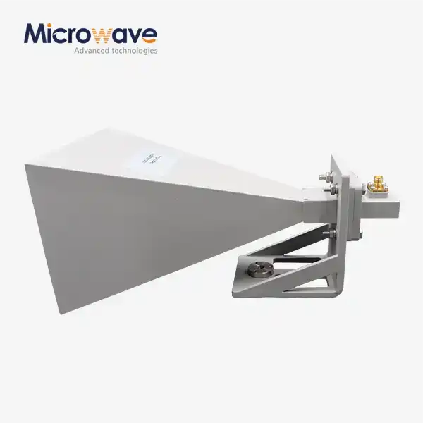
The horn is a transitional element that changes directed waves from square or round waveguides into radiation that travels through empty space. Its flared walls gradually make the aperture bigger, which lets impedance matching happen and lowers reflections. The lens then changes the radiated wavefront, fixing phase errors and focusing the energy into a narrow beam. This two-way operation cuts down on spillover losses and keeps phase coherence across the aperture, which is very important for long-distance satellite uplinks and accurate radar tracking systems.
Material Properties That Shape Performance
Lens materials need to have stable dielectric constants and low loss tangents across all temperature ranges where they are used. Rexolite, PTFE-based composites, and special ceramics for millimeter-wave bands are all common options. Material choice affects not only how weak the signal is but also how stable it is at high temperatures and how long it lasts mechanically. We've made custom lens assemblies for aerospace clients who needed materials that could handle going from -40°C to +85°C without losing any performance. These materials met ISO 9001:2008 standards for quality consistency.
Radiation Patterns and Gain Characteristics
The antenna gain is directly related to the size and efficiency of the aperture. A well-made horn lens system can get 20–40 dBi gain with side lobe levels below -25 dB, which is very important for keeping interference to a minimum in frequency bands that are already busy. The main lobe width of the radiation pattern affects the coverage area and spatial resolution. Narrower beams are better for point-to-point satellite links, while wider patterns are better for radar monitoring on the ground. Far-field pattern verification is possible in our 24 m Microwave Darkroom. This makes sure that delivered products match certain characteristics before they are sent to system integrators.
Critical Design Factors Influencing Signal Quality and Performance
To find the best horn lens antenna configurations, you have to balance a lot of different parameters that depend on each other. Small changes in the angle of the horn flare or the curvature of the lens can change the frequency response, change the purity of the polarization, or add unwanted phase ripple. When procurement teams look at sources, they should pay close attention to how makers control these factors through precise machining and tested measurement procedures.
Lens Geometry and Dielectric Properties
The focal length and beam convergence are controlled by the lens curve profile. Spherical lenses are easy to make, but they have distortions at large opening angles. Elliptical or hyperbolic shapes fix these problems, but they are harder to machine. It is also very important that the dielectric constant is the same across the whole lens. Differences of more than 2% can hurt phase coherence, which can lead to beam squint or bigger side lobes. Our technical team regularly checks the dielectric properties of materials at several locations using network analysers that are set to NIST-traceable standards. We provide this information to defense contractors who need full material traceability.
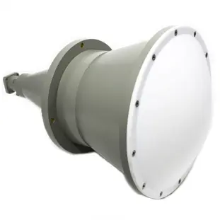
For uses with low loss, loss tangent numbers below 0.001 are normal. Higher values cause heat and signal loss, which is a big problem in high-power radar transmitters where several kilowatts of power go through the lens. We've come up with our own special composite formulas for clients that work at 94 GHz. These formulas achieve loss tangents of 0.0003 while keeping the mechanical strength needed for marine antenna systems, including horn lens antenna designs, that are hit with salt spray and vibration.
Horn Aperture Dimensions and Flare Angle
Gain and beamwidth are directly affected by the size of the aperture. Larger apertures focus more energy into smaller beams, but they also add weight and wind loads, which is a problem for ground station antennas that are exposed to bad weather. How fast the waveguide expands is controlled by the flare angle. The best flare angles depend on the frequency and pattern characteristics you want. Steeper angles make designs smaller, but they also increase the chance of pattern flaws and VSWR. Our engineers use electromagnetic simulation software that is checked against measurements made in our Antenna Plane Near and Far Field Measuring Recombination Chamber to make sure that designs are correct before they are put into production.
Mechanical Alignment and Manufacturing Tolerances
If the horn and lens are not lined up correctly by even a fraction of a millimeter, the performance is worse. Coma aberrations are caused by angular errors, and beam direction errors caused by horizontal offsets are not acceptable for satellite tracking uses. For important interfaces, we keep mechanical tolerances within ±0.05 mm. Coordinate measuring machines and optical alignment fixtures help us do this. Procurement managers should ask for alignment verification data and information on how to fix problems. Reliable makers will keep records of these steps and send performance test results with every shipment.
Comparative Analysis: Horn Lens Antenna vs. Other Antenna Types
To pick the best antenna topology, you need to know how to balance electrical performance, physical limitations, and the cost of production. Different uses call for different answers, and picking the wrong ones can result in high costs or poor performance in the field.
Horn Lens vs. Parabolic Reflector Systems
Large ground stations mostly use parabolic reflectors because they work well and have been proven to be reliable. These reflectors have great gain and pattern control, but they need strong mounting systems and very accurate surface accuracy (usually µ/20 RMS) to work at their best. Horn Lens Antennas have similar electrical performance but take up less space, which makes them better for mobile platforms or locations that don't have a lot of room. Reflectors usually cost less when the aperture is bigger than one meter, while horn lens antenna assemblies are more cost-effective for smaller systems with built-in feed networks and small profiles.
Comparison with Dielectric and Flat Lens Technologies
Using metamaterials or Rotman lens architectures in flat lens antennas lets you steer the beam without turning the antennas mechanically, which makes them a good choice for phased array alternatives. Making these designs is more difficult, and their bandwidths are usually smaller than those of horn lens antenna systems. Although dielectric rod antennas are easy to use and cheap, they don't let you control the gain or the pattern. When making purchases, it's important to think about how much bandwidth is needed. Our horn lens antenna products can cover 20% fractional bandwidths, which makes them good for multi-band satellite communications where frequency agility is important.
Phased Array and Microstrip Antenna Alternatives
Electronic beam direction and multi-beam features are not possible with fixed-horn lens antenna systems. This flexibility comes with higher costs, more power use, and more work when calibrating. Microstrip patch arrays work well for industrial mass production, but they don't work well at millimeter-wave frequencies because there are more losses and the fabrication limits get tighter. Defence contractors often ask for horn lens antenna feeds for their phased array subarrays. Our precise manufacturing makes sure that elements perform the same way on all large array faces. We share this idea with system builders during technical consultations: this hybrid method strikes a good balance between cost and capability.
Designing for Application-Specific Requirements
In the real world, deployment environments have needs that go beyond electrical specifications. Different market groups have different buying objectives based on environmental extremes, operational speed, and lifecycle costs.
Satellite Ground Station and Space Communication Applications
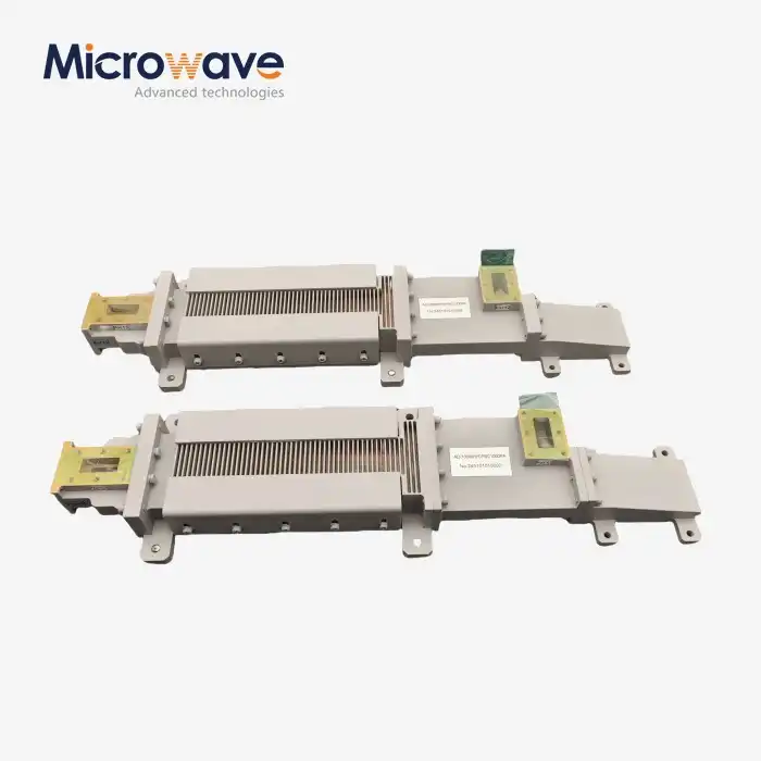
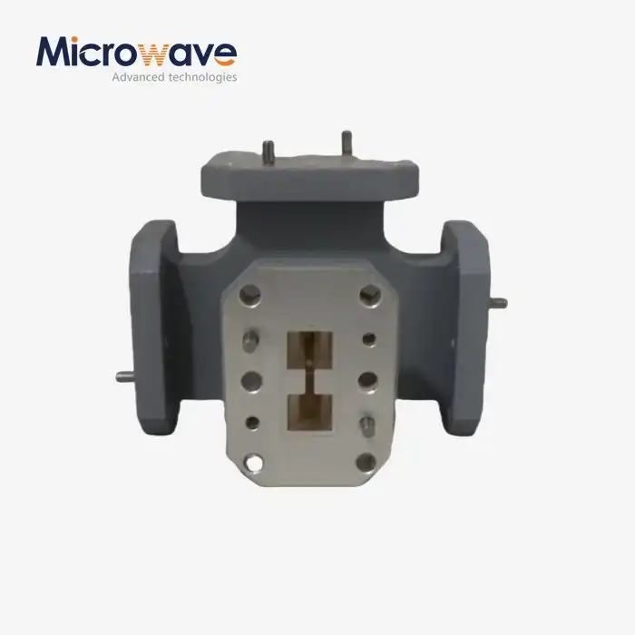
To get the most out of their link gaps, ground stations that serve LEO, MEO, and GEO satellites need to cover a lot of frequencies and work very efficiently. For example, our X-Band feed networks show this: they are custom-designed for satellite ground stations to make sure that signals for HD video, data, and voice interactions are sent quickly and easily. These groups include horn lens antennas, as well as diplexers and polarizers. They are sent as tested subassemblies that are ready to be put together in tracking pedestals. RoHS compliance and full material disclosure meet the rules for installations in places that are bad for the environment.
Radar and Defense System Considerations
Military observation radars focus on low side bands to cut down on noise and make it easier to tell the difference between targets. Shock, vibration, and temperature cycling tests according to MIL-STD-810 make sure that designs are ready to be used in the field. We've given defense companies horn lens antenna systems that can work in everything from the Arctic to the desert, with coatings and seals that keep water out and prevent corrosion. Defence procurement regulations require audit trails that are backed up by traceability documentation like raw material certifications and dimensional inspection reports.
Industrial and 5G Infrastructure Deployments
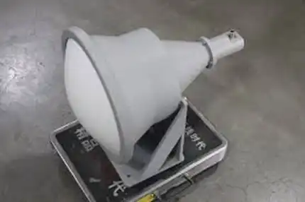
Wireless backup links and private 5G networks need options that are both cost-effective and easy to set up quickly. Horn Lens Antennas for these markets are made to be both effective and efficient, and they usually use standard designs that have been tweaked to work with certain frequency bands. Our OEM services help telecom equipment makers add our antennas to their lines of products by giving them expert support for fitting help and fixing problems. Quick turnaround design shortens the time it takes to develop a product, which helps clients get it to production faster while lowering the risk.
Practical Tips for Procurement: Ensuring Quality and ROI
To strategically source Horn Lens Antennas, you need to look at more than just price quotes from suppliers. The success of a project depends on how reliable and capable the provider is in the long run. This is why due diligence is so important.
Evaluating Manufacturer Credentials and Certifications
Getting ISO 9001 certification means that quality management is being done in a planned way, but procurement teams should check the scope and audit results. Ask about the calibration of your measuring tools. Our labs keep track of national standards and keep quality guides with information on when to calibrate equipment that clients can look over. Certifications like ISO 14001 and ISO 45001 show that a company cares about worker safety and the environment, which are becoming more and more important in procurement policies that stress corporate social responsibility.
Technical Documentation and Performance Verification
Measured S-parameters, radiation patterns, and VSWR across the whole working band should be included in full datasheets. When specs only list "typical" values without tolerance ranges, be wary. These values often hide differences in performance. To check for uniformity, ask for sample test results from recent production lots. With every order, Advanced Microwave Technologies Co., Ltd. sends full test documentation that includes pattern cuts at different phi angles and time-domain reflectometry data that shows where the internal breaks are.
Pricing Models and Total Cost of Ownership
Unit costs at the start are only one part of the procurement equation. Think about the wait time, the minimum order quantity, and the tooling costs for making unique designs, including specialized components such as a horn lens antenna. Costs can be cut for programs with more than one project by using volume discounts and framework agreements. Check out the warranty terms and the after-sales support. When problems happen, providers with global logistics networks and quick-response expert teams can keep your business running. We've set our prices so that they can cover both small amounts of prototypes for R&D labs and large amounts of production for OEM clients. Our quotes are clear and show all of the costs, plus they point out places where we can save money.
Conclusion
For horn lens antennas to work well in tough RF situations, the properties of the materials, the accuracy of the geometry, and the quality of the manufacturing must all be carefully considered. Procurement experts have to judge suppliers based on more than just their specs. They also have to look at how well they can measure, maintain quality, and understand how to use their products. When done right, the way lens dielectrics, horn geometry, and mechanical alignment work together produces performance that is better than the sum of its parts. Choosing partners with approved test facilities, thorough recording practices, and the ability to adapt to different needs will help you meet your signal quality goals in a wide range of operating situations.
FAQ
1. What frequency ranges are suitable for horn lens antenna designs?
Horn Lens Antennas work well from 500 MHz to 110 GHz, but they are most often used above 2 GHz, which is when their small size benefits become noticeable. Lower frequencies need openings that are too big to be useful, but millimeter-wave bands gain from being able to precisely control the beam. The choice of frequency is based on the application's bandwidth needs and the way signals travel through the air for outdoor setups.
2. How do environmental factors affect horn lens antenna performance?
Lens dielectric values change when the temperature changes, which leads to frequency shift and pattern changes. When rain and ice build up on lens surfaces, they cause reflections and losses. These effects can be lessened by using the right materials and protective radomes. For military and aerospace uses, environmental testing according to MIL-STD standards is needed to make sure that the product works well in a range of operating temperatures and circumstances.
3. What customization options are available for specialized applications?
Manufacturers offer opening sizes that can be changed, frequency band optimization, polarization setups, and feed networks that are built in. Custom lens profiles can fix certain wavefront errors or make shaped beams that meet coverage needs. Mechanical interfaces can be used with existing mounting hardware, and environmental treatments can be changed to fit the conditions of deployment. Talking about the specifics of an application with engineering teams helps find the best ways to customise it in a way that balances cost and performance.
Partner with a Trusted Horn Lens Antenna Manufacturer
Advanced Microwave Technologies Co., Ltd. can help you with your most difficult signal quality problems because they have been working with RF components for more than twenty years. Our ISO-certified manufacturing processes and measurement tools that can go up to 110 GHz in our 24 m Microwave Darkroom make sure that every Horn Lens Antenna assembly meets strict performance standards. Our engineering team creates designs that are perfect for your needs, whether you're looking for precise feeds for satellite ground stations, ruggedized radar parts, or custom OEM solutions. Our defence contractors, telecom operators, and research institutions depend on our complete supply chain systems and strict quality controls for mission-critical deployments. Email craig@admicrowave.com right away to talk about the details of your project, get technical documentation, or set up an evaluation of a prototype. As a direct supplier, we can help you meet project milestones and get the most out of your investment with our quick technical support and low prices.
References
1. Balanis, Constantine A. "Antenna Theory: Analysis and Design, Fourth Edition." John Wiley & Sons, 2016.
2. Olver, A.D., et al. "Microwave Horns and Feeds." IEEE Press Series on Electromagnetic Wave Theory, 1994.
3. Silver, Samuel. "Microwave Antenna Theory and Design." MIT Radiation Laboratory Series, Volume 12, McGraw-Hill, 1949.
4. Clarricoats, P.J.B. and Olver, A.D. "Corrugated Horns for Microwave Antennas." IEE Electromagnetic Waves Series, 1984.
5. Milligan, Thomas A. "Modern Antenna Design, Second Edition." IEEE Press, Wiley-Interscience, 2005.
6. Stutzman, Warren L. and Thiele, Gary A. "Antenna Theory and Design, Third Edition." John Wiley & Sons, 2012.

_1733738410152.webp)