





Straight Waveguide Design Basics for RF Applications
A straight waveguide is a hollow metallic tube with a uniform cross-section that transmits electromagnetic waves along its length without bending or tapering. In RF applications, these precision-engineered conduits enable low-loss signal propagation by confining electromagnetic energy within rigid metallic boundaries. By maintaining consistent dimensional tolerances and high-conductivity surfaces, straight waveguides deliver reliable performance across defined frequency bands, making them indispensable in radar systems, satellite ground stations, and aerospace communication equipment where signal integrity cannot be compromised.
Understanding Straight Waveguides in RF Applications
What Is a Straight Waveguide, and How Does It Work?
Straight waveguides work by enclosing electromagnetic fields in a conductive shell. This lets certain propagation modes move quickly along the waveguide's axis. In coaxial cables, the dielectric layer separates the inner and outer conductors. Waveguides, on the other hand, use boundary reflections to guide waves, so there are no dielectric losses. Because of this design concept, they work especially well at microwave and millimeter-wave frequencies, where regular cable systems lose too much signal.
The main idea behind it is the cutoff frequency, which is the lowest frequency at which a certain mode can travel. Signals get weaker and weaker below this point. Most waveguides are rectangular, and they can support both TE (transverse electric) and TM (transverse magnetic) modes. In real-world applications, TE10 is usually the most important mode.
Material Selection and Performance Impact
Waveguide effectiveness depends a lot on how well the material conducts electricity and how well the structure is built. Aluminium alloys are commonly used in commercial satellite communications and industrial measurement systems because they are a good balance between weight, cost, and electrical performance. Copper is a better conductor than other materials, so it lowers insertion loss in high-power radar applications where even a few decibels make a difference. Brass is used for prototyping and testing in specific situations where ease of use is more important than ultimate performance.
Treatments on the surface, like gold or silver plating, lower losses even more by lowering the resistance of the skin effect at high frequencies. When you work with Advanced Microwave Technologies Co., Ltd., we choose materials based on the conditions in which they will be used. For example, marine radar systems need materials that don't rust, and aerospace platforms that work in high and low temperatures need materials that don't change shape.
Frequency Ranges and Dimensional Constraints
The size of the waveguide directly affects the frequency bands that can be used. Standard waveguide names, like WR-90, WR-62, and WR-28, refer to the broad size in hundredths of an inch. Each size is best for a certain frequency range. The WR-90 waveguide works from 8.2 to 12.4 GHz (X-band), and the WR-28 waveguide works from 26.5 to 40 GHz (Ka-band).
Precision in dimensions is very important. Cutoff frequency, impedance matching, and mode purity are all affected by manufacturing errors. Our ISO 9001:2015-certified production methods keep measurements within micrometres, so your waveguide systems meet strict performance standards from the time they are made until they are used in the field.
Critical Applications Across Industries
In the defence, military, and telecoms industries, mission-critical systems are held together by straight waveguides. To accurately track planes, air traffic control radar systems need X-band waveguide feed networks. Ku-band and Ka-band waveguide runs are used by satellite ground stations to connect high-gain antennas to transceiver equipment with little signal loss. Military surveillance platforms use tough waveguide systems that keep working even when they are vibrated, shocked, or heated and cooled.
Custom waveguide configurations are used by industrial research institutions to test antennas, characterize materials, and study how signals travel. We have a 24-meter microwave darkroom with far-field measurement tools from 0.5 to 110 GHz. This lets us check waveguide performance across the whole operational spectrum and give procurement teams and system designers data they can trust.
Comparing Straight Waveguides with Other Waveguide Types
Structural and Performance Differences
Knowing the differences between waveguide types helps you choose the right components. When installing flexible waveguides in places where travelling lines change directions or equipment shakes while it's working, they can be made with corrugated or articulated construction. Flexibility makes things easier, but it also means more insertion loss and less power handling than rigid straight sections.
Curved waveguides, like E-plane, H-plane, or twist bends, change the paths of signals, but if the bend lengths are too small, they can cause mode conversion and standing wave echoes. Straight waveguide sections are often used to provide stable signal transmission between components, while tapered waveguides go from one cross-section or waveguide standard to another. This lets systems work together, but they need to be carefully designed to keep return loss to a minimum.
Coaxial transmission lines work well across a wide range of frequencies and take up little space, but they lose more power and are less efficient at microwave frequencies than waveguides. Because circular waveguides can rotate without changing how waves travel, they are useful in radar and antenna applications where having a variety of polarizations is important.
Performance Metrics That Drive Selection
To choose between waveguide types, you need to look at a number of technical factors. Straight waveguides shine in this area, usually showing losses below 0.1 dB per meter at X-band frequencies. Insertion loss measures signal attenuation per unit length. Straight waveguide cross-sections maximize both breakdown voltage and heat dissipation by maximizing surface area and regular field distributions, which are both important factors in power handling capacity.
Each design has a different operational frequency. Most rectangular waveguides have bandwidth ratios of about 1.5:1 (maximum frequency to minimum frequency). Rigid waveguides can go up to 2:1 or more, but they do so at the cost of more complexity and loss. The right trade-off depends on the application. For example, standard rectangular designs work best for narrowband radar feeds, while ridged or dual-mode designs may be needed for wideband electronic warfare systems.
These performance factors have a direct effect on the total cost of the system. Engineers evaluating options should consider not just component pricing but also installation labour, maintenance access, and long-term reliability. Straight waveguides have fewer connection points and simpler mechanics, which makes them less likely to break in hard operating conditions.
Essential Design Principles for Straight Waveguides
Wave Propagation Theory and Design Fundamentals
Maxwell's equations describe how electromagnetic waves move through waveguides, with conductive walls acting as boundary conditions. Which propagation modes can exist are based on the shape, and each mode has its own field patterns and propagation factors. To keep multimode interference from lowering signal quality, design engineers must make sure that single-mode operation stays within the intended frequency range.
In rectangular waveguides working in the main TE10 mode, the cutoff wavelength is equal to twice the broad dimension. To keep wideband transmissions from being distorted by dispersion, the operating frequency should be well above the cutoff frequency. For practical designs, the middle of the suggested frequency range is where loss is lowest, and power handling is highest.
Material Selection Impact on Conductivity and Durability
The electrical conductivity has a direct effect on insertion loss through skin effect losses, which focus the flow of current at the sides of conductors. Aluminum 6061-T6 alloys are great for commercial telecommunications infrastructure and general industrial uses because they are inexpensive and light while still being able to conduct electricity well. Copper alloys are more expensive and heavier, but they cut losses by 20 to 30 percent in high-power military radar systems, where every decibel of efficiency means a longer range of detection.
When prototyping or making small amounts, brass is easier to work with than other metals. Our research team at Advanced Microwave Technologies Co., Ltd. can help you choose the right materials based on your performance needs, the surroundings, and your budget, including selecting suitable components such as a straight waveguide. Our manufacturing methods are RoHS-compliant, which means they are good for the environment and don't hurt the performance of the electronics.
In precision assemblies that work in a wide range of temperatures, thermal expansion coefficients are important. The choice of material affects the stability of the dimensions, which in turn affects the electrical performance across a range of temperatures. We use our temperature-controlled measurement tools to take these things into account during plan validation.
Dimensional Analysis and Frequency Mode Optimization
Both the cutoff frequency and the characteristic resistance are based on the cross-sectional measurements. Larger waveguides help lower frequencies travel, but they are bigger and heavier, which are important things to think about on aircraft platforms where every gram affects how much fuel they use and how much they can carry. At millimeter-wave frequencies, smaller cross-sections raise the cutoff frequency, which lets more components fit into a smaller space.
The thickness of the wall has to be able to withstand mechanical stresses during installation and operation while still staying the same size. Thin walls make things lighter, but they can also bend, which can change how they conduct electricity. Our ability to do structural analysis makes sure that waveguide systems meet the mechanical requirements for uses that have to deal with vibration, shock, and pressure differences.
Design optimisation finds the best mix between different needs. When purchasing teams look at custom waveguide assemblies, they should talk to manufacturers early on in the design process. Our technical consulting services help you find the best combinations that meet your power performance goals while keeping costs and delivery times under control.
Procurement Guide for Straight Waveguides
Key Considerations for B2B Buyers
For waveguide procurement to go well, there must be clear frequency requirements and interface specifications. Waveguide flange types, such as UG-style, cover-style, or choke flanges, must match current system parts to make sure they fit correctly and that the electricity flows smoothly. In the request-for-quotation paperwork, procurement engineers should list the frequency range, maximum VSWR (voltage standing wave ratio), insertion loss limits, and mechanical interface standards.
When choosing materials, energy function and environmental needs are balanced. Finishes that don't rust, like iridite coating or electroless nickel plating, are needed for marine and coastal installations. For aerospace uses, you need lightweight alloys that can be tracked and come with material approvals. Defense companies have to make sure that their sources have the right security clearances and follow the rules for export control.
Customization needs go beyond basic wiring requirements. Custom mechanical features may be needed for mounting holes, wire entry ports, and sealing against the surroundings. Our OEM services at Advanced Microwave Technologies Co., Ltd. can meet specific needs by using collaborative design methods that turn application needs into specifications that can be made.
Advantages of Custom Manufacturing and Bulk Orders
Custom waveguide parts make system integration better by adding features that are specific to the application during production instead of changing them in the field. Integrated mounting clamps, perfectly placed interface flanges, and environmental sealing that is already installed cut down on installation time and increase reliability. Custom sizes get rid of the need for adaptors, which add extra entry loss and could be a point of failure.
When you buy in bulk, you get economies of scale that help programs that need a lot of the same assemblies. Pricing based on volume lowers the cost per unit while keeping quality the same across production lots. Scheduled supplies line up the supply of parts with integration goals, which speeds up production and lowers the cost of keeping inventory on hand.
Our production ability and good supply chain management allow us to do both fast prototyping and high-volume manufacturing. Lead times usually last between two weeks and six weeks for standard configurations and difficult custom setups. If you need your program to be done faster, you can choose one of the faster options.
Identifying Reliable Suppliers and Quality Certifications
The choice of supplier has a huge effect on the success of a program. For products such as straight waveguides, quality standards are concrete proof of the ability to make things and keep an eye on the whole process. Getting ISO 9001:2015 certification shows that you have well-thought-out quality management systems in place for planning, making, and testing. ISO 14001:2015 certification shows that a company cares about the environment, and ISO 45001:2018 certification shows that a company cares about workers' health and safety.
As important as certifications are, technical skills are also important. Suppliers should keep measurement tools that are calibrated and can be traced back to national standards, keep records of checking processes, and include test data with the gear they give. Our labs at Advanced Microwave Technologies Co., Ltd. have vector network analyzers that can measure waveguide performance up to 110 GHz. This makes sure that every assembly meets certain electrical requirements before it is shipped.
Suppliers who become trusted partners offer reliable delivery and support after the sale, while suppliers who only fulfil orders do not. Our expert support team helps with installation, fixes problems, and offers a warranty that covers your investment for the life of the product.
Conclusion
The straight waveguide design uses electromagnetic theory, precise manufacturing, and material science to send signals reliably in RF applications that are very demanding. Knowing about propagation rules, size limits, and material trade-offs helps you make smart purchasing choices that improve system performance while keeping costs low. When you work with experienced makers, you can get access to technical support, quality certifications, and after-sales service that keep mission-critical systems running for as long as they are needed. This is true whether you choose standard configurations or custom assemblies. Well-designed waveguide assemblies are still very important for infrastructure in aerospace, defense, and telecommunications, even as microwave technology moves toward higher frequencies and tougher environments.
FAQ
1. What materials are commonly used for straight waveguides?
Aluminium alloys are mostly used in business because they are cheap, light, and good at conducting electricity. Copper alloys are used in high-power military radars where the extra cost is worth it because they reduce losses. For samples and small production runs, brass is very easy to machine. In premium configurations, surface treatments like silver or gold plating make insertion loss even less of a problem.
2. How do dimensional variations affect frequency performance?
Cutoff frequency and operational bandwidth are based on cross-sectional dimensions. Larger waveguides can handle lower frequencies, but they are bigger and heavier. Tolerances in manufacturing affect VSWR, insertion loss, and mode purity. Accurate fabrication keeps electrical performance within specs in a variety of environments and frequency ranges.
3. Can I order custom-designed waveguides for specialized applications?
Of course. Custom waveguide parts make system integration better by making sure they have the right rings, mounting holes, and sizes for the job. Our engineering team at Advanced Microwave Technologies Co., Ltd works with clients to turn their specific needs into designs that can be made. These designs are then tested and documented in great detail. Based on how complicated the order is, custom lead times usually last between four and six weeks.
Partner with ADM for Expert Straight Waveguide Solutions
Advanced Microwave Technologies Co., Ltd makes waveguide assemblies that are precisely engineered to meet the specific needs of your high-performance RF system. We have been making straight waveguides for over 20 years and have ISO-certified processes. We support defense, aircraft, and telecommunications projects around the world by combining technical know-how with quick service. Our OEM services include unique designs, large sales, and fast prototyping. Our state-of-the-art 24-meter microwave darkroom is used for full testing. Email craig@admicrowave.com right now to talk about the details of your project and find out how our waveguide solutions can help your system work better and be more reliable.
References
1. Pozar, David M. Microwave Engineering, 4th Edition. John Wiley & Sons, 2012.
2. Balanis, Constantine A. Advanced Engineering Electromagnetics, 2nd Edition. John Wiley & Sons, 2012.
3. Collin, Robert E. Foundations for Microwave Engineering, 2nd Edition. IEEE Press, 2001.
4. Rizzi, Peter A. Microwave Engineering: Passive Circuits. Prentice Hall, 1988.
5. Marcuvitz, Nathan. Waveguide Handbook. Institution of Engineering and Technology, 1986.
6. Saad, Theodore S. Microwave Engineers' Handbook, Volume 1. Artech House, 1971.
YOU MAY LIKE
 VIEW MOREWater-cooled Twist Waveguide
 VIEW MOREWaveguide Miter Bend
 VIEW MOREWaveguide Sliding Termination
 VIEW MOREHigh Power Waveguide Differential Phase Shift Circulator
 VIEW MOREWG High Pass Filter
 VIEW MOREWaveguide Adjustable Support
 VIEW MORECoaxial Variable Attenuator
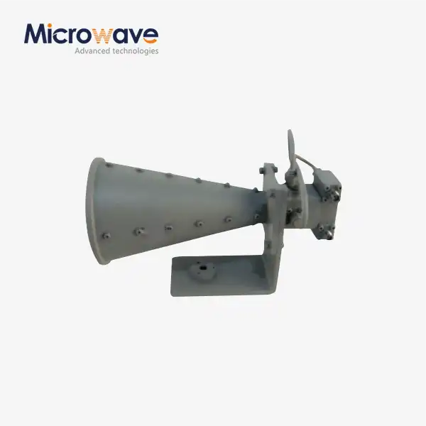 VIEW MOREDual Linear Broadband Dual Circular Polarization Horn Antenna
