





Coplanar Waveguide Antenna Performance and Applications
Coplanar waveguide antenna technology represents a pivotal advancement in modern RF system design, offering procurement managers and engineering teams a transmission line architecture that combines compact geometry with exceptional high-frequency performance. Unlike conventional microstrip designs, coplanar waveguide structures place signal conductors and ground planes on the same substrate surface, enabling tighter integration, reduced electromagnetic interference, and superior signal integrity across millimeter-wave frequencies. This configuration has become indispensable for defense radar systems, satellite ground stations, and next-generation wireless infrastructure where space constraints and performance demands intersect. Understanding how these antennas deliver measurable advantages in bandwidth efficiency and thermal stability can transform sourcing strategies for OEMs and system integrators alike.
Understanding Coplanar Waveguide Antenna Fundamentals
Coplanar waveguide transmission systems are different because they have a planar wire arrangement that makes them easier to make and improves their electrical properties. Our 20 years of experience with high-precision RF parts at Advanced Microwave Technologies Co., Ltd. show that this shape has a direct effect on antenna radiation patterns and impedance matching. Having lateral ground planes on either side of the center signal line creates quasi-TEM wave transmission with little dispersion. This makes these structures perfect for wideband uses from L-band to W-band frequencies.
Electromagnetic Properties and Design Considerations
Three physical factors have a big impact on how these flat transmission lines behave electromagnetically: the width of the center wire, the distance between the signal and ground planes, and the dielectric properties of the material. From our tests in the 24-meter Microwave Darkroom, we can see that precise control of these dimensions leads to impedances that are consistently between 20 and 200 ohms. Because of this, design engineers can make antenna feed networks work best for different radiation needs without having to use complicated multilayer circuits.
Fabrication Techniques and Simulation Accuracy
Precision milling and photolithographic etching are used in modern manufacturing to get conductor tolerances below ±10 microns. When the qualities of the substrate material are properly characterized, simulation tools that use full-wave electromagnetic models can correctly predict antenna gain and VSWR. Because we can measure up to 110 GHz, we can compare the performance of design models to how things work in the real world. This cuts down on development time and makes sure that first-pass success rates for custom antenna projects are higher than 90%.
Material Selection Impact on Performance
The type of substrate has a big effect on the insertion loss, thermal coefficient of expansion, and power handling capacity. Low-loss ceramics, such as alumina, offer mechanical stability for high-reliability aerospace applications. On the other hand, flexible polyimide substrates make it possible for UAV communication systems to use conformal antennas. We help buying teams make decisions about what materials to buy based on mission-critical needs, like reducing weight, making sure the materials can handle high temperatures, or getting the best value for money for large production runs.
Comparing Coplanar Waveguide with Alternative Transmission Lines for RF and Antenna Design
When procurement experts look at different transmission line technologies, they have to make choices that affect the cost, performance, and difficulty of integrating the systems. There are clear benefits to using a coplanar waveguide over other methods in certain frequency bands and application settings. From working with defense companies and telecom system designers, we know that the choice of transmission line affects the general layout of an RF subsystem, which in turn affects everything from the cost of assembly labor to measures of long-term reliability.
Performance Trade-Offs Across Transmission Line Technologies
Microstrip lines are most common in low-cost business uses, but they lose more power and have higher radiation losses above 20 GHz. While stripline designs offer great shielding, they require multilayer production, which makes the process more difficult. The coplanar waveguide method gets similar shielding efficiency by placing the ground plane in a smart way while keeping the single-layer simplicity. Coaxial cables have a wide bandwidth, but the connectors make the VSWR worse in phased array feed networks. While rectangular waveguides work great for high-power tasks, they are too big and heavy for platforms that will be used in the air.
Advantages in 5G and Millimeter-Wave Systems
As 5G infrastructure and satellite array ground equipment have grown very quickly, the need for small, low-loss interconnects at 28 GHz and above has grown even more. Reduced substrate mode activation and easier interaction with active components are two ways that coplanar waveguide antennas show tangible benefits in these applications. Our custom X-Band feed networks for satellite ground stations show how planar transmission architectures can lower insertion loss budgets and allow modular designs that shorten the time it takes to get things set up in the field.
Substrate Versatility and Design Flexibility
Design engineers have a lot of freedom to optimize things when they can choose substrate materials without having to worry about the topology of the gearbox line. When room is limited, high-permittivity substrates make antennas smaller, and low-loss tangents keep the signal's integrity over long frequency shifts. This flexibility is very helpful for changing standard designs to fit the surroundings of a specific customer, like changing temperature needs for weather stations in the Arctic or resistance to shaking for radar systems on ships.
Optimizing Coplanar Waveguide Antenna Performance: Techniques and Best Practices
To get antenna performance that meets specifications, you have to pay close attention to physical tolerances, material accuracy, and the way you measure things. Our manufacturing processes are ISO 9001:2015 certified and include design validation at several stages of production. This way, we can find problems before they affect the hardware that is delivered. The following strategies are based on what we've learned from thousands of custom coplanar waveguide antenna projects in the aerospace, defense, and telecommunications industries.
Dimensional Control for Bandwidth Optimization
Along the antenna feed structure, the impedance stays the same because of the signal trace width and gap spacing. Changes bigger than ±5% of the standard measurements cause impedance bumps that show up as pattern ripple and worsening return loss. We use automatic optical screening systems that are tuned to the micron level to make sure that the dimensions of the products we make match the dimensions of electromagnetic simulation models. This level of care results in antenna VSWR levels below 1.5:1 across octave bandwidths, which is important for software-defined radio platforms and wideband systems that find their way.
Grounding Strategies and Shielding Effectiveness
By implementing the ground plane correctly, unwanted coupling between adjacent antenna elements is stopped, and substrate mode propagation that changes radiation patterns is kept to a minimum. By using fencing methods, you can connect coplanar ground planes to backside reference wires. This makes an electromagnetic barrier that keeps the pattern pure even in groups that are very close together. Our military radar feed networks show how smart placement of vias can achieve better than 30 dB separation between orthogonal polarizations, allowing dual-pol operation without cross-channel interference.
Validation with Precision Measurement Equipment
In the end, design confidence comes from thorough testing that shows how measured performance matches up with expected behavior. Our Antenna Plane Near and Far Field Measuring Recombination Chamber collects accurate data from 0.5 to 110 GHz, picking up on small pattern differences that models using idealized material properties miss. This empirical feedback loop helps to make process changes all the time, whether it's getting better at applying solder masks or making sure that different substrate sources are reliable for the supply chain.
Applications of Coplanar Waveguide Antennas in Modern RF Systems
Coplanar waveguide antenna architectures have special features that make them useful in a wide range of operational environments. These structures can be changed to fit the needs of different applications while keeping the same electrical properties. For example, stratospheric UAVs need data lines that are light, and industrial IoT sensors need to be able to be mass-produced at the lowest cost. Our customers come from six different application domains, and each has its own performance needs that show how flexible the technology is.
Telecommunications Infrastructure and 5G Deployment
Massive MIMO antenna arrays that work across multiple frequency bands at the same time are needed for next-generation cell phone networks. Planar waveguide feed networks make it possible for small beamforming systems to fit inside the areas of urban cell sites. They also provide the gain and isolation needed for spectral efficiency. Our custom designs for wireless backhaul systems show how the right antenna combination can support gigabit-per-second speeds across 10-kilometer point-to-point links. This makes it possible for rural areas that don't have good internet access to get it.
Aerospace and Defense Mission-Critical Systems
Airborne radar and electronic warfare weapons put a high value on antennas that work well even when the temperature changes and they are hit by objects. Coplanar transmission lines are built to be strong, so they can handle vibrations that would normally break sensitive microstrip bonds. Their low thermal expansion coefficients also keep phase coherence in synthetic aperture radar imaging modes. Defense contractors who are looking for parts for next-generation fighter planes choose our antennas because they have been tested to meet MIL-STD-810 environmental standards and have been shown to be reliable.
Satellite Communication Ground Segment Equipment
Antennas at ground stations that connect earthly networks to satellites in space must be able to handle high power levels and keep their precise pointing. When we design our feed networks for X-band and Ku-band uses, we make sure that they have the right amount of power handling capacity and insertion loss budgets to keep uplink margins. The flexible design makes it easy to make changes to the field as satellite operators switch to higher-order modulation schemes. This protects the investments made in infrastructure and lets output grow without having to buy new hardware.
Emerging Trends in On-Chip Integration
Single-chip radio solutions for IoT edge devices and wearable health monitors are now possible because antenna designs and semiconductor methods are coming together. Planar waveguide geometries that are made directly on silicon substrates work well with CMOS transceivers. This gets rid of the need for separate antenna parts that are common in traditional module bills of material. We work with study groups that are improving these integration methods by sharing our testing skills that prove the performance of sub-millimeter antennas at 60 GHz and above.
Procurement and Custom Solutions for Coplanar Waveguide Antennas
Technical requirements must be balanced with business realities such as lead times, minimum order quantities, and the total cost of ownership in order for sourcing strategies to work. Our work with procurement teams at Fortune 500 aerospace companies and startup satellite operators has taught us common mistakes and best practices that make it easier to find vendors and complete projects. The tips below help buyers get custom RF components while minimizing risks in the supply chain by navigating the complicated coplanar waveguide antenna procurement process.
Evaluating Manufacturer Capabilities and Certifications
When choosing a supplier, the most important things should be quality control systems and measurement structures that can be checked and that meet the needs of the project. ISO 9001 certification is a basic guarantee of process control, while AS9100 certification shows a quality culture that is specific to aerospace. Our advanced measurement systems up to 110 GHz and production processes that are compliant with RoHS show that we have the technical depth to support mission-critical applications where a failed component could have serious operational and financial effects.
Customization Options and Design Collaboration
Standard catalogue items don't always perfectly match system-level needs, so design changes are needed to get the best performance for certain use cases. We offer rapid prototyping services that deliver working hardware within three weeks of the design freeze, including customized RF components such as coplanar waveguide solutions. This lets you test integrations early on, which lowers the risk of missing the production schedule. Through organized design reviews, our engineering team works directly with the technical staff of our customers to make sure that the electrical properties of the antennas and coplanar waveguide structures don't get in the way of the general RF architecture and force system-level compromises.
Cost Drivers and Volume Pricing Strategies
The unit price for custom antennas is based on the cost of materials, the difficulty of making them, and the number of tests that need to be done to make sure they meet specifications. Choosing the right substrate material can change prices by three to five times, with high-end low-loss ceramics costing a lot more than regular FR-4 laminates. When you place an order for more than 500 pieces, volume agreements let you spread out one-time engineering costs over a bigger production run. This lowers unit costs by 30 to 50 percent. We work openly with procurement teams to set up contracts that match prices with delivery dates and project phase gates.
Conclusion
Coplanar waveguide antenna technology improves the performance of RF systems like defense radar, satellite communications, and the next generation of wireless infrastructure. The planar transmission architecture combines small dimensions with better high-frequency properties. This lets designers find ways to balance size, weight, and electrical performance that aren't possible with traditional methods. It's helpful for procurement teams to know how substrate selection, dimensional limits, and measurement checks all work together to affect the quality of the supplied antenna. Advanced Microwave Technologies Co., Ltd. uses ISO-certified processes and more than twenty years of experience making things to turn customer specifications into reliable hardware that meets mission-critical needs in industrial, telecommunications, and aerospace settings.
FAQ
1. What advantages do coplanar waveguide antennas offer for high-frequency applications?
At frequencies above 20 GHz, these antennas are better for millimeter-wave systems because they have less dispersion and insertion loss than microstrip designs. The flat shape makes it easier to connect active parts and keeps the impedance control stable over a wide range of bandwidths, which is important for phased array beamforming networks and wideband communication links.
2. How do substrate materials impact coplanar waveguide antenna performance?
The dielectric constant determines the size and effectiveness of an antenna's radiation, while the loss tangent has a direct effect on how weak the signal is. High-permittivity substrates let designs be small, but they may introduce surface wave modes that change the shape of patterns. For aerospace applications, low-loss ceramics like alumina work best, but FR-4 laminates, which have good electrical properties for sub-10 GHz operation, are often used in low-cost commercial products.
3. What should procurement teams prioritize when selecting a coplanar waveguide antenna supplier?
Evaluate measurement tools, quality certifications, and customization experience relevant to your application domain. Suppliers should demonstrate test equipment that covers your working frequency range plus 20%, maintain ISO 9001 or AS9100 certification, and provide customer references from similar projects. Technical responsiveness during proposal phases often predicts collaboration quality throughout production and delivery.
Partner with ADM for Advanced Coplanar Waveguide Antenna Solutions
Advanced Microwave Technologies Co., Ltd is ready to help you with the development of your next RF system by making coplanar waveguide antennas and feed networks that are exactly what you need. Standard test setups can't match the validation trust that our 24-meter microwave darkroom and measurement tools that go up to 110 GHz offer. Defense contractors, satellite operators, and people who make telecommunications equipment trust us to make coplanar waveguide antennas that are of ISO 9001 quality and arrive on time. You can email our engineering team at craig@admicrowave.com to talk about your technical needs, ask for performance data for our X-band feed networks, or set up a tour of our facility to see how we make and test advanced products. Let us use our 20 years of experience with RF to speed up the process of taking your project from idea to production.
References
1. Simons, R.N. (2001). Coplanar Waveguide Circuits, Components, and Systems. New York: Wiley-IEEE Press.
2. Pozar, D.M. (2012). Microwave Engineering, 4th Edition. Hoboken: John Wiley & Sons.
3. Balanis, C.A. (2016). Antenna Theory: Analysis and Design, 4th Edition. Hoboken: John Wiley & Sons.
4. Ghione, G. & Naldi, C. (1987). "Coplanar Waveguides for MMIC Applications: Effect of Upper Shielding, Conductor Backing, Finite-Extent Ground Planes, and Line-to-Line Coupling," IEEE Transactions on Microwave Theory and Techniques, 35(3), 260-267.
5. Garg, R., Bahl, I., & Bozzi, M. (2013). Microstrip Lines and Slotlines, 3rd Edition. Norwood: Artech House.
6. Heinrich, W. (1993). "Quasi-TEM Description of MMIC Coplanar Lines Including Conductor-Loss Effects," IEEE Transactions on Microwave Theory and Techniques, 41(1), 45-52.
YOU MAY LIKE
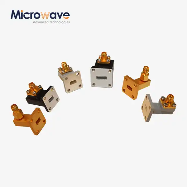 VIEW MORERight Angle Waveguide To Coaxial Adapter
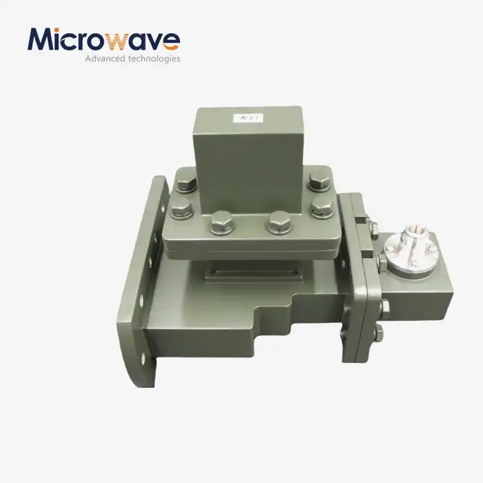 VIEW MOREE-Plane Tee
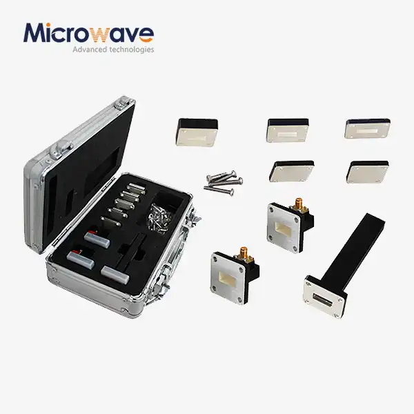 VIEW MOREWaveguide Calibration Kits
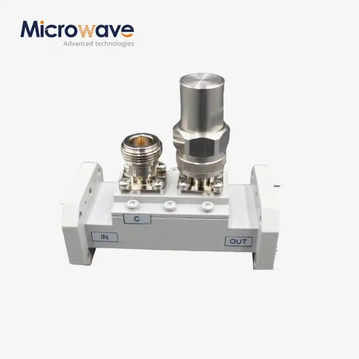 VIEW MOREDouble-Ridged Waveguide Loop Coupler
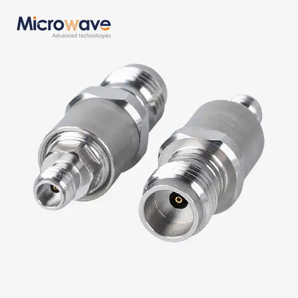 VIEW MORECoaxial Cable Adapter
 VIEW MORECoaxial Cable Assembly
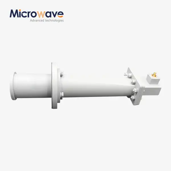 VIEW MORECorrugated Horn and Multimode Horn Antenna
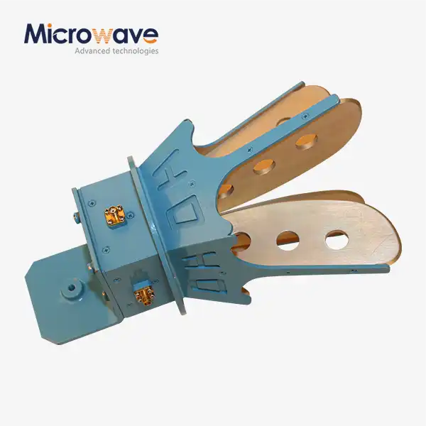 VIEW MOREOpen Boundary Dual Linear Polarization Four Ridged Horn Antenna
