Coaxial Load Performance Metrics Every Engineer Should Know
know how a coaxial load works. These inactive parts take in radio frequency energy, which stops signal echoes that could mess up data or damage pricey transmitters. When picking the right termination, you need to look at things like VSWR, power handling, and frequency range. These are all things that have a direct effect on how reliable the system is and how well the tests are done. Understanding these basics will help people who work for defense companies adjusting radar systems, satellite installers building ground stations, or research labs making prototypes of high-frequency circuits make better buying choices and run their operations more efficiently across all global RF uses.
Understanding Coaxial Load Basics and Key Performance Metrics
A coaxial load ends transmission lines by meeting their characteristic resistance, which in RF systems is usually 50 Ohms. This match stops reflected power from going back to the source. If it did, it would make standing waves, mess up signals, or make amps too hot. During tests, when antennas can't be linked, or when empty ports on hybrid couplers and circulators need to be properly terminated to keep the system balanced, engineers depend on these devices.
Impedance Matching and VSWR
Impedance matching makes sure that the most power can flow between parts. Reflections happen when the impedance of a load is different from the normal impedance of the system. This difference is measured by VSWR. A VSWR of 1.0:1 means there is a perfect match, while higher numbers mean there is more reflection. When commercial-grade terminations are used, the VSWR is usually less than 1.20:1. However, when used in Vector Network Analyzer (VNA) tests, accurate calibration loads can hit 1.05:1 or better. The CL line from Advanced Microwave Technologies has VSWR values below 1.2:1 from DC to 110 GHz. This gives engineers faith that reflected energy is still very small even at millimeter-wave frequencies.
Power Rating and Thermal Management
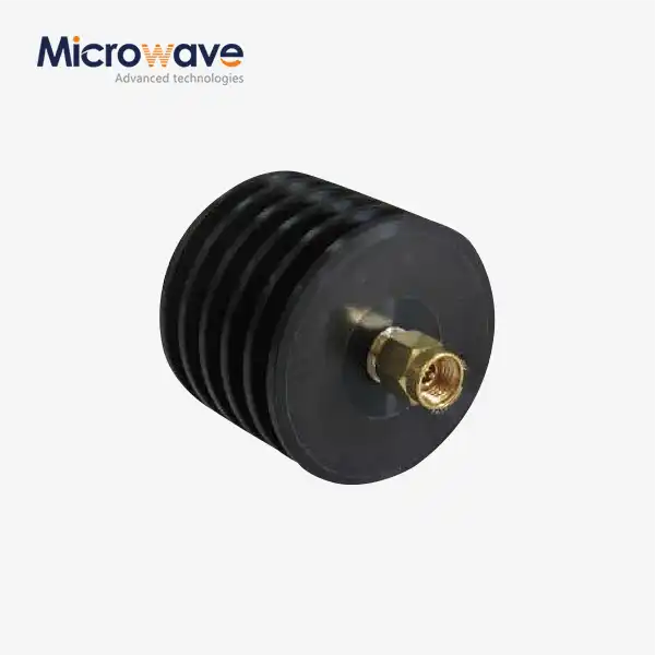
The power handling ability of a termination tells you how much RF energy it can safely give off as heat. If you don't give this number enough weight, a part could fail or the figure could be wrong. To account for changes in temperature and power spikes, engineers should choose loads that are rated 25 to 50 percent higher than their system's average output. The CL series from Advanced Microwave can handle up to 500 watts of continuous wave power. It uses advanced heat absorption materials and metal fin designs to keep working properly even when exposed to long periods of high power, like when testing radar or maintaining radio transmitters.

Frequency Range and Bandwidth
For different uses, different frequency ranges are needed. Satellite ground stations that work in the Ku-band need terminations that work effectively at 12 to 18 GHz. At the same time, new 5G test systems work in millimeter-wave bands above 24 GHz. When you use a termination outside of its recommended frequency range, it changes from a resistive load to a reactive component. This can lead to high VSWR and possibly damage to the equipment. The CL series covers frequencies from DC to 110 GHz, so it can work with both old communication systems and cutting-edge 6G research. This means that buying teams only need to deal with one provider for all of their frequency needs.
Return Loss and Insertion Loss
In terms of return loss, power levels were shown in decibels. Higher numbers mean better impedance matching. A 20 dB return loss means that only 1% of the power that comes in is sent back. When looking at attenuators or through-line devices, insertion loss is important. But when looking at terminations, which are made to take all forward power, it's not so important. When engineers are changing test sets, they need exact terminations with return loss of more than 20 dB to make sure the readings are correct. When testing the responses of low-noise amps or filters, this is very important.
How to Evaluate and Choose the Best Coaxial Load for Your Applications?
To choose an RF termination, you need to make sure that the technical requirements match the needs of the application. When defense companies choose ruggedized parts for flying radar, they will be given different weights than when research labs make prototypes of experimental antenna arrays. Knowing these differences makes buying easier and stops mistakes that cost a lot of money.
Assessing System Requirements
Start by writing down the working frequency, highest output power, connection type, and weather conditions of your machine Coaxial Load. For an outdoor base station that works at 2.6 GHz and puts out 100W, it needs a termination that can handle at least 150W of constant power and can work in temperatures ranging from -40°C to +85°C. The ports must also be waterproof. The CL line from Advanced Microwave can work in temperatures ranging from -55°C to +125°C and uses RoHS-compliant materials. It has SMA, N-Type, TNC, and 2.92mm connections, so it can be used in tough military and business telecom settings.
Comparing Terminations with Related RF Components
Even though they are different, terminations, attenuators, and directional couplers all control the flow of signals. Attenuators lower the level of a signal while letting energy pass through. They are useful in test setups that need to lower the power level in a controlled way. Terminations take in all incoming energy, making them perfect for checking transmitters or empty ports without radiation. For monitoring, directional couplers take a sample of some forward or reflected power, while terminations get rid of all echoes. Before choosing components, procurement teams need to be clear about whether their application needs to absorb energy (termination), weaken signals (attenuation), or watch power (coupling).
Procurement Considerations for B2B Clients
Beyond technical specs, procurement managers look at how reliable a provider is, how well they can customize products, and how well they can handle transportation. When you buy a lot of things for a production line, you get savings, and the quality stays the same across all batches. Space-constrained uses in aircraft modules or small test setups can be met by custom designs that include changed power rates, different types of connectors, or custom physical measurements. Advanced Microwave Technologies offers full OEM services, including designing custom terminations in very short amounts of time while still keeping ISO 9001:2008 certification and RoHS compliance. Their global transport network makes sure that delivery times are always met, which is very important for projects like defense contracts or satellite launches.
Installation, Testing, and Maintenance: Ensuring Long-Term Load Performance
Proper installation and ongoing maintenance prevent performance degradation and extend component lifespan. Even high-specification terminations underperform when improperly integrated or neglected over operational cycles.
Step-by-Step Installation Guide
Verify that the termination's connector matches your system's interface—mismatched threads or gender causes mechanical damage and poor electrical contact. Hand-tighten connectors to the manufacturer's specified torque (typically 5-7 in-lbs for SMA and 12-15 in-lbs for N-type) using calibrated torque wrenches; over-tightening deforms center pins, while under-tightening creates intermittent connections. Mount high-power terminations on heat sinks or in ventilated enclosures, ensuring adequate airflow around cooling fins. For precision measurements, allow thermal stabilization for 15-30 minutes after powering on before taking readings.
Testing and Calibration Procedures
After installation, measure VSWR using a VNA or return loss bridge across the operating frequency range. Compare results against the datasheet specifications—deviations exceeding tolerance may indicate connector damage or counterfeit components. Apply low power initially, monitoring termination surface temperature with infrared thermometers; excessive heat suggests inadequate thermal management or power rating mismatch. Document baseline measurements for future comparison, establishing a performance history that aids troubleshooting when system behavior changes.
Maintenance Tips and Troubleshooting
Inspect coaxial load connectors quarterly for corrosion, dirt accumulation, or mechanical wear—even minor contamination degrades VSWR. Clean connectors with lint-free swabs and isopropyl alcohol, avoiding abrasive materials that scratch plating. Replace terminations showing physical damage, discoloration from overheating, or VSWR degradation beyond specification. In high-power applications, schedule thermal imaging inspections annually to identify hot spots indicating internal resistive film degradation. Maintaining detailed service logs supports predictive maintenance, reducing unplanned downtime and extending procurement cycles.
Advanced Insights: Optimizing Coaxial Load Performance Metrics
Mission-critical applications demand peak termination performance. Identifying bottlenecks and leveraging recent technological advances unlocks measurable improvements in system stability and measurement precision.

Identifying Performance Bottlenecks
Elevated VSWR often stems from connector interface issues rather than the termination itself. A mismatch between connector phases (test port vs. termination gender) or worn coupling mechanisms introduces reflections. High-power dissipation failures usually trace to inadequate thermal pathways—mounting terminations directly on metal chassis improves heat sinking compared to suspended installations. In low-PIM applications, standard terminations using magnetic materials or poorly bonded junctions generate passive intermodulation products; switching to low-PIM variants utilizing non-magnetic alloys and high-linearity resistive films eliminates this noise source in full-duplex communication systems.
Strategies for Performance Enhancement
Implement proper grounding techniques—bonding termination housings to chassis ground reduces electromagnetic interference pickup. In multi-port systems, terminate all unused ports immediately; even one unterminated port can create resonances affecting active channels. For wideband applications spanning decades of frequency, use multiple frequency-optimized terminations rather than single wideband units; specialized designs achieve better VSWR at specific bands. Pair precision terminations with high-quality cables featuring consistent impedance and low loss to maintain end-to-end system performance.
Innovations in Termination Technology
Recent materials science advances enable terminations operating at higher frequencies with improved thermal performance. Aluminum Nitride (AlN) and Beryllium Oxide (BeO) ceramic substrates offer superior thermal conductivity compared to traditional alumina, maintaining stable impedance under temperature cycling. Precision CNC machining achieves tighter mechanical tolerances, critical for millimeter-wave applications where dimensional variations of micrometers affect electrical performance. Advanced Microwave Technologies incorporates these innovations into their CL series, leveraging over 20 years of manufacturing expertise and ISO-certified quality control to deliver terminations meeting evolving industry demands.
A defense contractor transitioning from L-band to C-band radar required terminations (coaxial load) supporting 6-18 GHz with improved power handling. By specifying Advanced Microwave's CL series with enhanced thermal management and verifying VSWR across temperature extremes in their 24m microwave darkroom, they achieved 15% better return loss consistency compared to previous suppliers. This improvement reduced false target detections in field trials, validating the investment and establishing a preferred supplier relationship for future programs.
Conclusion
Mastering RF termination performance metrics empowers engineers and procurement professionals to select components that enhance system reliability and measurement accuracy. Understanding VSWR, power handling, frequency range, and thermal management enables informed decisions that prevent costly equipment damage and project delays. Advanced Microwave Technologies' CL series exemplifies precision engineering, delivering DC to 110 GHz coverage, 500W power handling, and VSWR below 1.2:1 in compact, durable packages. Whether calibrating VNAs in research labs, protecting transmitters during base station commissioning, or terminating unused ports in satellite ground stations, choosing the right termination optimizes performance and justifies procurement investments through measurable operational improvements.
FAQ
1. How do I determine the correct power rating for my application?
Calculate your system's maximum continuous output power, then apply a safety margin of 25-50% to account for temperature variations and transient peaks. Ambient temperatures above 25°C reduce effective power handling; consult derating curves in datasheets. If your transmitter outputs 100W average in a 40°C environment, specify a termination rated for at least 150-200W to ensure reliable long-term operation without thermal stress.
2. Why does termination VSWR matter if the load absorbs all power?
Even small reflections from imperfect VSWR affect measurements and can damage sensitive sources. A VSWR of 1.20:1 reflects roughly 8% of incident power—negligible in many applications but problematic when calibrating VNAs or testing low-noise receivers where accuracy depends on known impedance environments. Defense and aerospace contracts often mandate VSWR below 1.15:1 to meet stringent system specifications.
3. Can I use the same termination across multiple frequency bands?
Only if the termination's specified frequency range covers all intended bands. Using a DC-3 GHz termination at 5 GHz introduces reactive impedance components, creating high VSWR and risking equipment damage. Wideband terminations like Advanced Microwave's CL series (DC-110 GHz) accommodate diverse applications, eliminating the need for band-specific inventory while maintaining performance consistency across the entire spectrum.
Partner with Advanced Microwave Technologies for Precision RF Termination Solutions
Specifying the right RF termination impacts project success from initial testing through field deployment. Advanced Microwave Technologies combines over 20 years of microwave engineering expertise with ISO 9001:2008-certified manufacturing to deliver CL series coaxial loads trusted by defense contractors, satellite operators, and research institutions worldwide. Our terminations support DC to 110 GHz frequencies, handle up to 500 Watts, and achieve VSWR below 1.2:1—backed by comprehensive OEM customization services for unique connector types, power ratings, and mechanical configurations. As a leading coaxial load manufacturer, we provide rapid prototyping, competitive volume pricing, and global logistics support to streamline your procurement process. Contact craig@admicrowave.com today to discuss your application requirements, request technical datasheets, or obtain project-specific quotations. Let ADM's proven reliability and engineering precision become the foundation of your next RF system success.
References
1. Pozar, D. M. (2011). Microwave Engineering, 4th Edition. Hoboken: John Wiley & Sons.
2. Collin, R. E. (2001). Foundations for Microwave Engineering, 2nd Edition. New York: IEEE Press.
3. Balanis, C. A. (2016). Antenna Theory: Analysis and Design, 4th Edition. Hoboken: John Wiley & Sons.
4. Rizzi, P. A. (1988). Microwave Engineering: Passive Circuits. Upper Saddle River: Prentice Hall.
5. Misra, D. K. (2001). Radio-Frequency and Microwave Communication Circuits: Analysis and Design. New York: John Wiley & Sons.
6. IEEE Standard 287-2007. (2007). IEEE Standard for Precision Coaxial Connectors (DC to 110 GHz). New York: Institute of Electrical and Electronics Engineers.