Coaxial Cable Adapter vs Waveguide Adapter: When to Use Which
Engineers and system designers frequently encounter a critical dilemma in RF and microwave systems when signal loss reaches unacceptable levels or system integration becomes problematic. The question of selecting between a Coaxial Cable Adapter and waveguide adapter can determine whether your satellite communication link maintains signal integrity or whether your radar system achieves the required detection range. This comprehensive guide addresses the fundamental differences, practical applications, and decision-making criteria that will help you choose the optimal adapter solution for frequencies ranging from DC to 110 GHz, ensuring your system operates at peak performance while avoiding costly mistakes in signal transmission and system compatibility.
Understanding Coaxial Cable Adapter Technology and Core Functionality
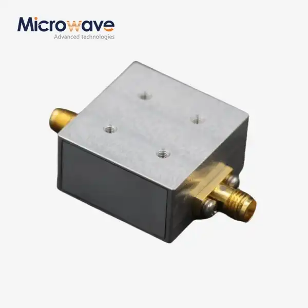
The Coaxial Cable Adapter represents a fundamental connectivity solution in modern RF and microwave systems, serving as the critical interface between different coaxial transmission lines. Advanced Microwave offers coaxial adapters designed to connect coaxial cables with different types of connectors or to convert between different sizes and impedances, playing a vital role in ensuring compatibility and seamless integration of various RF and microwave systems while maintaining signal integrity between connections. These adapters function as precision-engineered components that accommodate the transverse electromagnetic mode transmission characteristic of coaxial systems, where the electric and magnetic fields exist perpendicular to the direction of propagation within the coaxial structure. The fundamental design of a Coaxial Cable Adapter incorporates a central conductor surrounded by a dielectric insulator and an outer conductor shield, providing excellent impedance matching typically at fifty ohms for most RF applications and seventy-five ohms for video and telecommunications systems.
The operational frequency range of modern Coaxial Cable Adapter designs extends from direct current applications up to forty gigahertz, making them extraordinarily versatile for applications spanning from audio frequency systems through microwave communications. At Advanced Microwave Technologies Co., Ltd., our cable adapters are crafted to meet the highest industry standards, including ISO 9001 certification and RoHS compliance, ensuring that every adapter delivered maintains exceptional performance characteristics across demanding applications in satellite communication, defense, aerospace, and navigation industries. The manufacturing precision achieved through advanced production techniques ensures that connector interfaces fit securely and precisely, optimizing signal integrity and enhancing overall system performance even in high-frequency applications where minor imperfections can cause significant signal degradation. The versatile compatibility of these adapters allows seamless integration with numerous coaxial cable types including semi-rigid, flexible, and conformable configurations, supporting connector families such as SMA, N-type, BNC, TNC, and specialized military-grade connectors that serve specific application requirements across commercial and defense sectors.
Technical Specifications and Performance Parameters
Technical specifications of high-quality Coaxial Cable Adapter designs directly influence system performance and reliability. The frequency range spanning DC to 40 GHz enables these adapters to serve applications from legacy communication systems operating at lower frequencies through cutting-edge millimeter-wave technologies approaching the Q-band spectrum. Impedance standardization at fifty ohms ensures compatibility with the vast majority of RF test equipment, transmitters, receivers, and antenna systems throughout the telecommunications and aerospace industries. Connector type availability including SMA, N-type, BNC, and TNC configurations provides flexibility in system design, allowing engineers to interface equipment from different manufacturers and technology generations without signal degradation. Material selection utilizing brass, stainless steel, or aluminum construction combined with gold, nickel, or silver plating options ensures optimal electrical conductivity while providing corrosion resistance essential for long-term reliability in harsh environmental conditions. The voltage standing wave ratio specification of 1.15:1 or better guarantees minimal signal reflection at the adapter interface, preserving transmitted power and maintaining system efficiency across the operational bandwidth. Temperature range capability from negative fifty-five degrees Celsius to positive one hundred sixty-five degrees Celsius enables deployment in extreme environments from arctic installations to high-temperature aerospace applications without performance degradation.
The precision manufacturing processes employed in producing these Coaxial Cable Adapter components utilize advanced machining techniques, computer-controlled quality verification systems, and stringent testing protocols that ensure dimensional accuracy within micrometers. This precision directly translates to reliable mechanical mating between connector pairs, minimizing insertion loss and maintaining consistent electrical performance throughout the adapter's operational lifetime. Environmental protection features incorporating RoHS compliance demonstrate commitment to sustainable manufacturing practices while ensuring that adapter components contain no hazardous substances that could compromise environmental safety or regulatory compliance in international markets. The broad application scope of these adapters encompasses high-frequency systems across both commercial telecommunications infrastructure and military defense platforms, offering versatile and reliable performance in demanding environments where signal integrity cannot be compromised and system downtime carries severe operational and financial consequences.

Application Scenarios and Performance Benefits
Coaxial Cable Adapter technology delivers exceptional performance across diverse application scenarios where signal transmission reliability and system flexibility represent critical requirements. In satellite communications systems, these adapters ensure reliable signal transmission for both uplink and downlink channels, facilitating stable and uninterrupted communication between satellites and ground stations in space applications where signal degradation could result in complete communication loss. The low insertion loss characteristics minimize signal attenuation in the transmission path, preserving the link budget margin necessary for reliable communication across vast distances between Earth and orbital platforms. In telecommunications infrastructure, Coaxial Cable Adapter components play crucial roles in base station equipment and operator networks, maintaining stable and efficient signal integrity that supports seamless communication across mobile and fixed telecom systems serving millions of users simultaneously. The durability achieved through robust construction using high-quality materials ensures these adapters withstand the challenges of demanding environments, offering long-lasting operation and maintaining high performance under harsh conditions including extreme temperatures, humidity, vibration, and electromagnetic interference.
The customization options available for Coaxial Cable Adapter specifications enable tailored solutions meeting specific requirements across diverse applications. Engineers can specify custom connector types, plating options, and physical dimensions to perfectly suit unique system architectures and operational parameters. Frequency range adaptations allow optimization for specific bands of operation, whether supporting legacy systems operating in the L-band or cutting-edge communications utilizing Ka-band frequencies for high-data-rate transmission. The high performance supported by wide frequency coverage up to 40 GHz ensures steady and reliable signal transmission over various high-frequency applications, enhancing overall system efficiency and performance across military radar systems, commercial satellite terminals, aerospace navigation equipment, and scientific instrumentation. The minimization of both insertion loss and return loss through optimized design guarantees the highest signal integrity while reducing energy waste, ultimately improving general system efficiency and extending the operational range of communication links where every fraction of a decibel in signal strength can determine mission success or failure.
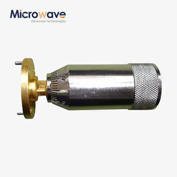
Waveguide Adapter Fundamentals and Operational Principles
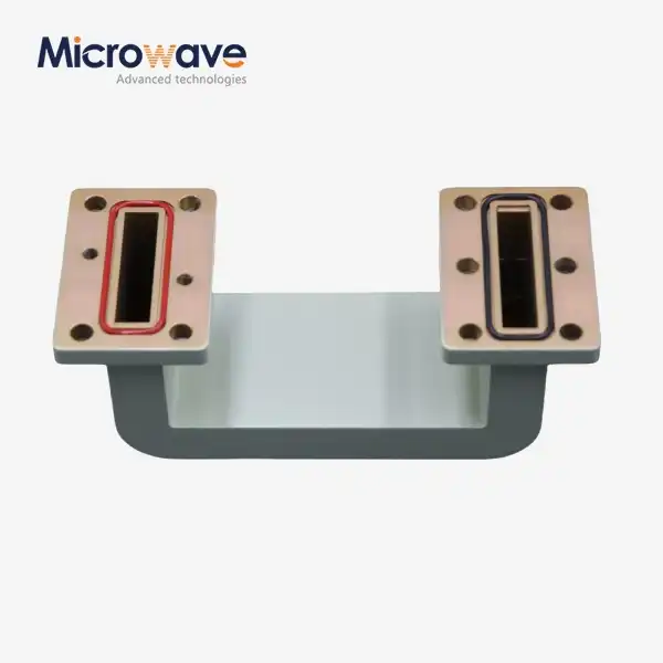
Waveguide adapters represent specialized components designed for high-frequency, high-power applications where coaxial solutions encounter fundamental limitations. These adapters enable transitions between different waveguide standards, facilitate connections to coaxial systems, or provide interface solutions for test equipment and antenna feeds operating in the microwave and millimeter-wave spectrum. The operational principle of waveguide transmission differs fundamentally from coaxial systems in that electromagnetic energy propagates through a hollow metallic structure rather than along a conductor-dielectric interface. This distinction becomes increasingly important at frequencies above approximately ten gigahertz, where waveguide solutions demonstrate superior performance characteristics including dramatically lower insertion loss, substantially higher power handling capability, and enhanced immunity to external electromagnetic interference compared to coaxial alternatives. The physical construction of waveguide adapters typically involves precision-machined rectangular or circular metallic structures with dimensions carefully controlled to support specific electromagnetic modes at designated frequency bands. For rectangular waveguides, the dominant TE10 mode features an electric field configuration with maximum intensity perpendicular to the broad wall of the waveguide structure. The cutoff frequency of the waveguide, determined by its physical dimensions, establishes the lower boundary of the operational frequency range, below which electromagnetic energy cannot propagate through the structure. Standard waveguide designations such as WR-90 for X-band applications or WR-42 for Ka-band systems specify precise internal dimensions that determine the operational frequency range, typically designed to operate from approximately 1.25 times the cutoff frequency up to 1.9 times the cutoff frequency to maintain single-mode propagation and avoid higher-order mode excitation that would compromise system performance.
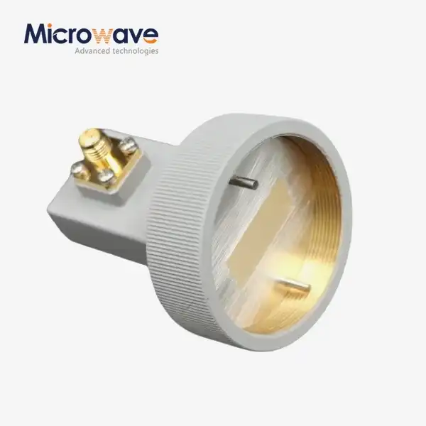
Waveguide to Coaxial Transition Technology
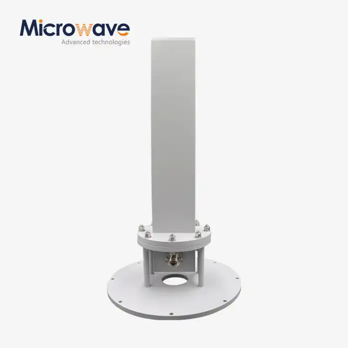
The transition between waveguide and coaxial transmission modes represents one of the most critical adapter functions in modern microwave systems. Waveguide to coaxial adapters incorporate specialized probe structures that couple electromagnetic energy between the fundamentally different field configurations of these transmission line types. In a typical transition design, the center conductor of the coaxial connector extends into the waveguide as a probe element, positioned perpendicular or parallel to the maximum electric field of the dominant TE10 mode within the rectangular waveguide structure. The probe depth and geometry require precise optimization to maximize energy coupling while minimizing excitation of higher-order modes that would degrade adapter performance. A quarter-wavelength short circuit positioned behind the probe launch point ensures unidirectional energy flow, eliminating backward radiation that would compromise insertion loss and create impedance mismatches affecting the overall system voltage standing wave ratio.
The coaxial connector typically mounts perpendicular to the waveguide flange at a ninety-degree angle, a configuration driven by the physical requirements of efficient probe coupling to the waveguide electric field structure. This perpendicular orientation allows the coaxial center conductor to serve as the radiating element that transforms the coaxial transverse electromagnetic mode into the waveguide TE10 mode with minimal energy reflection. The impedance transformation from the fifty-ohm coaxial system to the waveguide characteristic impedance, which varies with frequency and waveguide dimensions, occurs through the carefully designed probe structure whose electrical length and position within the waveguide determine the adapter's frequency response and impedance matching characteristics. Advanced designs may incorporate multi-section transformers or tapered transitions to achieve broader bandwidth performance while maintaining low voltage standing wave ratio across the operational frequency range. These sophisticated transition structures enable seamless integration of coaxial test equipment with waveguide transmission systems, allowing engineers to leverage the flexibility and convenience of coaxial connections while accessing the superior performance characteristics of waveguide transmission for high-power, low-loss applications.
Critical Decision Factors: When to Select Coaxial Cable Adapter Solutions
The selection of Coaxial Cable Adapter technology proves optimal for specific system requirements and operational scenarios where the inherent advantages of coaxial transmission outweigh the performance limitations at higher frequencies and power levels. The primary consideration favoring coaxial solutions involves operational frequency ranges below approximately eighteen gigahertz, where modern low-loss coaxial cables and high-quality connectors deliver acceptable performance without the dimensional constraints and installation complexity associated with waveguide systems. For applications requiring flexible routing through equipment racks, around obstacles, or through confined spaces, the mechanical flexibility of coaxial cables represents an overwhelming advantage that waveguide systems simply cannot match despite their superior electrical performance characteristics. The ability to bend coaxial assemblies around corners with minimum bend radius specifications typically ranging from five to ten times the cable diameter enables system designers to accommodate complex mechanical layouts that would be impossible or prohibitively expensive using rigid waveguide structures requiring precision bends and carefully aligned flange connections.
Cost considerations frequently drive the selection of Coaxial Cable Adapter solutions for applications where budget constraints limit the available resources for transmission line infrastructure. The material costs, manufacturing processes, and installation labor for coaxial systems typically represent a fraction of equivalent waveguide implementations, particularly for shorter transmission line runs where the cumulative insertion loss disadvantage of coaxial solutions remains within acceptable system link budget margins. The widespread availability of standardized coaxial connectors and adapters from multiple manufacturers ensures competitive pricing and eliminates single-source dependencies that could compromise long-term system supportability. For test and measurement applications, laboratory setups, and prototype development work, the convenience of quickly reconfiguring coaxial connections without specialized tools or alignment procedures accelerates system integration and troubleshooting activities that would consume significantly more time using waveguide components requiring torque wrenches, precision alignment, and gasket installation procedures.
Frequency Range and Bandwidth Considerations
The operational frequency range represents the most fundamental parameter determining whether Coaxial Cable Adapter technology provides adequate performance for a specific application. For systems operating from DC through approximately six gigahertz, high-quality coaxial solutions deliver excellent performance with insertion loss typically below 0.5 decibels per meter for premium cables such as low-loss corrugated designs. At these frequencies, the skin depth in copper conductors remains sufficient to maintain low surface resistance, and dielectric losses in high-quality polytetrafluoroethylene insulation materials remain manageable. Applications including most commercial telecommunications systems, GPS receivers, legacy radar installations, and lower-frequency satellite communication ground segments operate comfortably within this frequency range where Coaxial Cable Adapter technology provides reliable, cost-effective connectivity without the dimensional and installation constraints of waveguide alternatives.
As operational frequencies increase into the X-band spectrum from eight to twelve gigahertz, careful selection of coaxial cable types becomes critical to maintain acceptable system performance. Semi-rigid and low-loss flexible coaxial cables utilizing foamed dielectric materials and precision-controlled manufacturing processes can deliver insertion loss characteristics approaching one decibel per meter at these frequencies, acceptable for moderate transmission line lengths in applications where the flexibility and installation convenience of coaxial solutions justify the increased attenuation compared to waveguide alternatives. The Coaxial Cable Adapter components connecting these transmission lines must maintain equally stringent performance specifications, with high-quality connectors featuring gold-plated contacts, precision-machined interfaces, and carefully controlled dimensional tolerances to minimize reflections and insertion loss at the interconnection points. For transmission line runs exceeding several meters at X-band frequencies, the cumulative insertion loss of coaxial solutions begins to significantly impact system link budgets, potentially necessitating increased transmitter power or larger receive antenna apertures to compensate for signal attenuation in the transmission line infrastructure.
Optimal Scenarios for Waveguide Adapter Implementation
Waveguide adapter technology becomes the preferred solution when system requirements demand maximum performance at high frequencies, high power handling capability, or minimal signal loss over extended transmission line runs. The fundamental advantage of waveguide transmission emerges at frequencies above approximately ten gigahertz, where the insertion loss of even premium coaxial cables increases dramatically while waveguide attenuation remains remarkably low. For X-band radar systems operating at nine to ten gigahertz with high peak power transmission requirements, waveguide solutions can handle kilowatt-level pulsed power without breakdown or excessive heating that would damage coaxial cables within minutes of operation. The power handling superiority of waveguides stems from the absence of a center conductor and solid dielectric material, eliminating the primary heat concentration points and dielectric breakdown mechanisms that limit coaxial cable power capacity. Applications including air traffic control radar installations, military surveillance systems, and high-power satellite ground station transmitters routinely employ waveguide transmission lines and associated adapter components to achieve reliable operation at power levels impossible with coaxial alternatives.
The exceptionally low insertion loss characteristics of waveguide systems prove critical for applications where signal-to-noise ratio represents the limiting factor in system performance. For satellite communication ground stations receiving weak signals from geostationary satellites approximately thirty-six thousand kilometers above Earth's surface, every tenth of a decibel in transmission line loss directly degrades the system noise figure and reduces the achievable data rate or link availability. Waveguide transmission lines for these applications typically exhibit insertion loss below 0.1 decibels per meter at Ku-band frequencies, compared to several decibels per meter for coaxial alternatives. This dramatic performance advantage enables ground station designers to position low-noise amplifiers in environmentally controlled equipment shelters rather than directly at the antenna feed point, simplifying maintenance access and improving long-term reliability while maintaining competitive system noise figures through the use of low-loss waveguide feedlines connecting the antenna to the receiver equipment.
High-Frequency Millimeter-Wave Applications
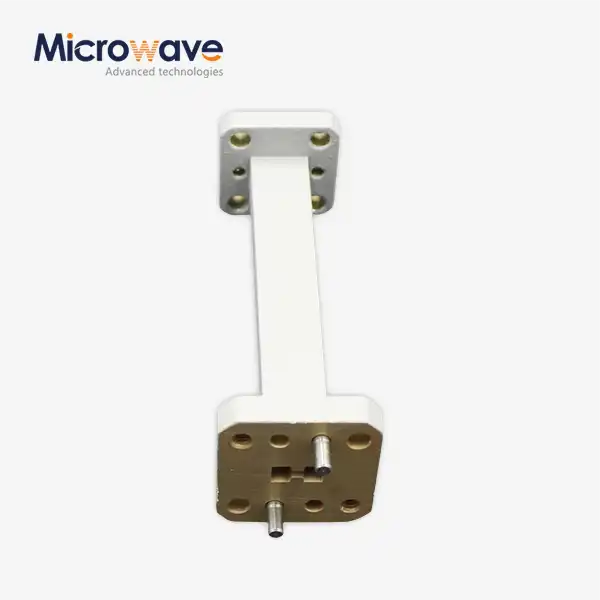
The advantages of waveguide adapter technology become absolutely compelling for millimeter-wave applications operating above thirty gigahertz where coaxial solutions face insurmountable performance limitations. At Ka-band frequencies spanning twenty-seven to forty gigahertz, skin effect in coaxial conductors forces current flow into extremely thin surface layers, dramatically increasing effective resistance and insertion loss to levels that render coaxial transmission impractical for all but the shortest interconnection distances. Waveguide systems operating in these frequency bands maintain insertion loss typically below 0.2 decibels per meter for standard rectangular waveguide types, enabling transmission line runs of tens of meters while preserving acceptable signal levels for high-data-rate communication links. Applications including satellite communication systems utilizing Ka-band for high-throughput data transmission, advanced radar systems operating at millimeter-wave frequencies for enhanced resolution, and radio astronomy installations receiving signals from celestial sources universally employ waveguide transmission technology with associated waveguide adapters providing necessary interface functions between system components.
The mechanical rigidity that represents a disadvantage for waveguide systems in flexible routing applications becomes an asset for installations requiring long-term dimensional stability and environmental protection. Outdoor waveguide runs for cellular base station backhaul links, microwave relay installations, and point-to-point communication bridges utilize pressurized waveguide systems that maintain dry nitrogen atmosphere within the transmission line structure, eliminating moisture condensation that would cause signal loss variations with temperature and humidity changes. The waveguide adapters in these systems incorporate specialized gas barrier flanges and pressure monitoring ports that ensure system integrity throughout years of continuous operation in harsh outdoor environments where coaxial solutions would degrade rapidly due to connector corrosion, cable jacket deterioration, and moisture ingress into dielectric materials. Military and aerospace applications demanding maximum reliability under extreme environmental conditions including shock, vibration, temperature excursions, and electromagnetic interference routinely specify waveguide transmission solutions with ruggedized waveguide adapters that maintain electrical performance specifications throughout the system operational lifetime without degradation or maintenance requirements that would compromise mission readiness.

Hybrid System Design and Adapter Integration Strategies
Modern RF and microwave systems frequently incorporate both coaxial and waveguide transmission technologies within a single system architecture, leveraging the specific advantages of each technology for different portions of the signal path. This hybrid approach requires careful integration of Coaxial Cable Adapter and waveguide adapter components to maintain overall system performance while optimizing cost, flexibility, and reliability across the complete transmission chain. A typical satellite communication ground station exemplifies this hybrid architecture, utilizing precision waveguide components for the critical low-noise receive path from the antenna feed through the initial low-noise amplifier, then transitioning to coaxial interconnections using high-quality Coaxial Cable Adapter components for flexible routing between equipment racks within the environmentally controlled equipment shelter. The waveguide to coaxial transition adapter represents the critical interface component in this architecture, requiring careful specification to minimize insertion loss and reflection while providing the mechanical interface between the rigid waveguide feed system and flexible coaxial distribution network serving receiver, spectrum analyzer, and monitoring equipment.
The selection of appropriate adapter types and specifications for hybrid system implementations demands comprehensive understanding of the signal characteristics, power levels, frequency ranges, and environmental conditions throughout the transmission path. Engineers must carefully allocate the system link budget, accounting for insertion loss contributions from each adapter, transmission line segment, and interconnection point to ensure adequate signal margins for reliable operation under worst-case conditions including component aging, temperature extremes, and manufacturing tolerance variations. For transmit paths carrying high power from solid-state or vacuum tube amplifiers to antenna feed systems, the power handling capability of each component requires verification against both continuous-wave and peak pulse power specifications to prevent component damage or performance degradation during normal system operation. The transition point between coaxial and waveguide sections typically occurs at locations where power levels have been reduced through distribution networks or increased through amplification stages, allowing designers to exploit the flexibility of coaxial routing where power levels permit while reserving waveguide transmission for high-power sections where coaxial alternatives would prove inadequate.
System Performance Optimization Through Proper Adapter Selection
Achieving optimal system performance through proper adapter selection requires methodical analysis of frequency response, insertion loss, voltage standing wave ratio, and power handling specifications for every interconnection point within the signal path. The cumulative effect of multiple adapter transitions can significantly degrade system performance if individual component specifications are marginal or improperly matched to the application requirements. Advanced Microwave Technologies Co., Ltd. provides comprehensive engineering support including detailed technical specifications, insertion loss data across specified frequency ranges, and power handling ratings under various operating conditions to enable system designers to accurately predict overall transmission path performance and identify potential bottlenecks requiring design optimization. The availability of custom Coaxial Cable Adapter designs with specific connector combinations, frequency range optimization, and specialized materials or plating options enables tailored solutions addressing unique system requirements that standard catalog products cannot adequately serve.
The importance of maintaining consistent impedance throughout the transmission path cannot be overstated, as impedance discontinuities at adapter interfaces generate signal reflections that degrade the voltage standing wave ratio and reduce effective power transfer efficiency. High-quality Coaxial Cable Adapter components feature precision-machined interfaces that maintain the fifty-ohm characteristic impedance with minimal deviation, typically achieving voltage standing wave ratio specifications of 1.15:1 or better across the operational bandwidth. This stringent specification ensures that reflected power remains below one percent of incident power, preserving signal integrity and maximizing power delivery to antenna systems or receiver front-ends where every milliwatt of signal power contributes to system performance. For applications demanding the ultimate performance, specialized low-VSWR adapter designs incorporating multi-section impedance transformers or carefully optimized transition geometries can achieve voltage standing wave ratio specifications approaching 1.05:1, virtually eliminating reflections and enabling precision measurements or maximum power transfer in demanding applications where standard adapter specifications prove inadequate.
Conclusion
Selecting between Coaxial Cable Adapter and waveguide adapter solutions fundamentally depends on frequency range, power handling requirements, installation flexibility needs, and cost constraints. Coaxial adapters excel below eighteen gigahertz with flexible routing, while waveguide adapters dominate high-frequency, high-power applications demanding minimal loss.
Cooperate with Advanced Microwave Technologies Co., Ltd.
Advanced Microwave Technologies Co., Ltd. stands as your trusted China Coaxial Cable Adapter manufacturer, China Coaxial Cable Adapter supplier, and China Coaxial Cable Adapter factory with over twenty years of expertise delivering High Quality Coaxial Cable Adapter solutions globally. Our ISO-certified facilities produce Coaxial Cable Adapter for sale with competitive Coaxial Cable Adapter price structures supporting applications from satellite communications through defense aerospace systems. We offer comprehensive OEM services including rapid prototyping, custom connector configurations, and frequency range adaptations with China Coaxial Cable Adapter wholesale options for volume requirements. Our expert engineering team provides installation guidance, troubleshooting support, and technical consultation ensuring your system achieves peak performance. Contact craig@admicrowave.com today to discuss your specific requirements and discover how our proven supply chain, advanced 24m Microwave Darkroom testing capabilities up to 110 GHz, and commitment to quality through ISO 9001, ISO 14001, and ISO 45001 certifications deliver the reliable connectivity solutions your mission-critical applications demand with fast delivery and exceptional after-sales support.
References
1. Balanis, Constantine A. "Advanced Engineering Electromagnetics." John Wiley & Sons, Second Edition
2. Pozar, David M. "Microwave Engineering." John Wiley & Sons, Fourth Edition
3. IEEE Standard 149-1979. "IEEE Standard Test Procedures for Antennas." Institute of Electrical and Electronics Engineers
4. Collin, Robert E. "Foundations for Microwave Engineering." McGraw-Hill Higher Education, Second Edition
5. MIL-STD-188-164A. "Interoperability Standard for Ground Mobile Forces Tactical Communication Systems." Department of Defense Interface Standard