


Cassegrain Antenna Design and Signal Performance
The cassegrain antenna design is a complex two-reflector structure that is now required for mission-critical radio frequency (RF) uses that need very good signal security. In this setup, there is a main parabolic reflector and a secondary hyperbolic sub-reflector close to the focus point. Together, they fold the signal path back toward the main dish tip. By putting the electronics and feed assembly behind the primary reflector, the Cassegrain antenna design gets rid of the need for long waveguide runs that are common in prime focus systems. This cuts down on insertion loss and greatly enhances the Gain-to-Noise Temperature (G/T) ratio, which is an important factor for high-frequency communications infrastructure, defense radar systems, and satellite communications.
Understanding Cassegrain Antenna Design Principles
We at Advanced Microwave Technologies Co., Ltd. have spent more than twenty years learning more about dual-reflector antenna designs. The Cassegrain antenna design comes from optical telescope principles that were changed to work with radio frequencies. Its engineering beauty solves basic problems that procurement teams in satellite communications and flight face every day.
Primary and Secondary Reflector Configuration
Signals are picked up by the primary reflector. Metal or a composite material with polished conical forms is used. The secondary hyperbolic sub-reflector sends signals to the feed horn behind the main dish. This form creates a compact focal point that shortens signal paths and fits heavier feed components without stressing support arms. Our manufacturers employ CNC cutting with micrometer-level inaccuracies to ensure surface accuracy. This keeps the phase consistent throughout the opening, which affects antenna performance and sidelobe blocking.
Signal Path and Beam Shaping Mechanics
The sub-reflector gathers up electromagnetic waves that combine in the focus area of the main reflector. The feed horn at the tip's mouth receives these messages from the hyperbolic curve. Path folding keeps the feed assembly steady relative to the mounting frame, which is critical. Flexure-induced phase errors in offset or prime focus designs don't occur. By accurately manipulating reflector surface profiles and sub-reflector location, engineers may create the optimal radiation patterns for diverse coverage demands. They can create narrow pencil beams for point-to-point satellite communications or larger ground station reception patterns.
Gain, Beamwidth, and Radiation Pattern Equations
The antenna gain using a Cassegrain antenna design is G = η(πD/λ)², where η is aperture efficiency (often 55-75%), D is primary reflector diameter, and λ is working wavelength. The beamwidth decreases with diameter, with a half-power beamwidth of approximately 70λ/D degrees. Our engineers utilise these correlations to help clients choose antenna sizes that match their budgets. The radiation pattern depends on the feed illumination curve. Our design balances edge illumination (efficiency) and overflow (noise temperature). Computer modelling tools like CST Microwave Studio and GRASP may parametrise these options before prototyping.

Feed System Variations and Reflector Geometries
Central feed systems position the feed horn on the antenna's sight line, improving symmetry and simplifying mechanical construction. In order to prevent the sub-reflector and feed supports from blocking the aperture, the offset Cassegrain antenna design tilts the optical path. For maximum aperture efficiency, utilise this setup. Our OEM services include specialised feed networks that operate with the user's low-noise amplifiers and frequency converters. The interface is easier and the system more dependable. Reflector shapes can be shaped to provide unequal beams that fit satellite ground coverage patterns or sidelobe bands that fulfil regulatory emission screens.
These design approaches provide performance improvements that our defence, aerospace, and telecommunications clients employ daily. The compact feed location and easy-to-reach fastening point behind the dish make cryogenically-cooled receiving systems easier to handle and service. Both characteristics decrease system lifetime ownership costs.
Performance Characteristics and Signal Optimization
Procurement engineers can make data-driven buying choices by understanding how Cassegrain antenna design turns into quantifiable performance measures. We regularly check these features in our 24-meter microwave lab, which works with frequencies ranging from 0.5 GHz to 110 GHz. This gives our customers test data that helps them plan how to integrate the systems.
Radiation Patterns and Beamwidth Control
Radiation patterns illustrate antenna gain changing with angle, which affects coverage and interference. Cassegrain antenna design produces symmetrical patterns with controllable sidelobe levels when properly set up. These are normally 20–25 dB below the main beam peak. Beamwidth is determined by aperture size and wavelength; reflector shaping lets you adjust the pattern without changing the reflector size. Circular scanning in our antenna plane, near and distant field measurement recombination chamber, gathers pattern data. This illustrates tiny aberrations that might reduce cross-polarization detection accuracy or generate interference hot spots in multi-satellite scenarios.
Gain Calculation Across Frequency Bands
Theory models ignore frequency-dependent losses; thus, practical gain must account for these. Increased frequency emphasises surface roughness. Our production methods maintain RMS surface fluctuations below λ/40 in millimeter-wave bands. Ohmic losses in reflector coatings worsen, notably in portable thin metal layer systems. Real gain data across operating bands is provided to consumers. These real-world parameters create 0.5 to 1.5 dB differences. This real-world data helps calculate satellite ground station link budgets and determine defence communication system margins for a variety of weather circumstances.
Noise Reduction and Sidelobe Minimization Strategies
The system noise temperature comes from the antenna (mostly sidelobe pickup of ground thermal emission) and the receiver. Cassegrain antenna design inherently blocks ground noise due to its upward-facing form and regulated sidelobe envelope. We optimise edge taper alterations and sub-reflector size to reduce sidelobe by 25–30 dB while maintaining 60–70% aperture efficiency. Working with defence and satellite operators has given us the optimum balance. Shaped supports or insulators reduce dispersion in strut blockage prevention. These solutions have helped our clients set up ground stations in RF-congested locations where preventing interference is crucial for smooth operations.
Simulation and Iterative Testing for Validation
Virtual prototyping with electromagnetic modelling software reduces development time and cost. We start our engineering approach by mapping performance trade-offs between design aspects using parametric models in HFSS or FEKO. Hybrid moment-method and ray-tracing approaches may forecast patterns, efficiency, and cross-polarization features of Cassegrain antenna design. Then we physically confirm in our lab. For this, our Antenna Plane Near and Far Field Measuring Recombination Chamber photographs the entire pattern cuts in azimuth and elevation planes. Differences between models and observations improve reflector surface limits or feed setting. This is repeated to ensure manufacturing units satisfy standards.
This all-around performance improvement has been achieved in microwave backbone systems, airborne radar platforms, and satellite communication networks. Our validated data sets aid regulatory filings, link budget studies, and integration planning, speeding up client go-live.
Procurement Considerations for Cassegrain Antenna Solutions
To find high-performance antenna systems, you need to pay attention to what the suppliers can do that goes beyond what is written in the specs. Twenty years of working with clients in defense, aircraft, and telecommunications have taught us what makes a project successful.
Custom Manufacturing and Design Services
Usually, antennas that are sold in stores don't meet all the exact needs of specific uses. We offer full OEM services that start with discussing your link budget and coverage needs and continue with electromagnetic modeling, mechanical design, and prototype testing. Our engineering team has made special Cassegrain antenna designs that can work with frequency bands from L-band to W-band and reach from 0.3-meter handheld terminals to 5-meter ground station dishes. Design services include integrating the feed network, specifying the radome for environmental protection, and customizing the mounting interface. This makes the antenna modules ready to be added to your bigger platform.
Our ISO 9001:2015-certified facilities can make custom parts that are accurate in size and have a good surface finish, both of which directly affect how well they work with radio waves. CNC machining centers keep the reflector's shape within 0.05 mm of accuracy across meter-class openings, and our quality control procedures check the electrical performance by measuring both near- and far-field patterns in great detail. Because of how strict we are about manufacturing, we have long-term relationships with aircraft OEMs and defense contractors that count on steady performance across large volumes of production.
Software Tools and Hardware Development Kits
Simulation models and reference drawings help in-house design teams speed up the development process. We offer electromagnetic models of our basic antenna setups in file types that work with CST, HFSS, and GRASP tools. This lets your engineers test different ways of integrating them before committing to hardware. The development kits come with mechanical interface models, RF performance data for different temperature and frequency ranges, and sample feed networks that show how to apply best practices. With these tools, client teams have been able to finish integrating antenna subsystems 40–50% faster than if they had started from scratch.
Our expert support goes beyond the initial design and includes helping with installation and making sure the system works properly. We've helped clients with site studies for ground station deployments, instructions on how to line antennas for mobile platforms, and ways to find system-level problems when they happen. With this wide range of support, we can be sure that the antenna performance we test in our lab will work in your setting.
Supplier Evaluation and After-Sales Support
Technical skill is the first step in building trusting relationships with suppliers. Other important factors include quick contact and on-time delivery. Our global transportation network ships to aerospace and military customers all over the world with packages of paperwork that meet export rules and quality tracking needs. Custom Cassegrain antenna designs usually take 12 to 16 weeks to deliver from the time the design is approved. However, for projects with tight deadlines, our development services can provide test units in as little as 6 to 8 weeks.
As part of after-sales assistance, extra parts are made available, performance is recalibrated, and there are update options that make products last longer. We keep a collection of parts for designs supplied in the last ten years so that systems that have been put into use can be fixed in the field. Technical support is available for as long as the product is in use. As mission needs change, our application engineers regularly help clients with system optimization, interference reduction, and performance proof.
Procurement professionals can email our team at craig@admicrowave.com to talk about unique project needs. Our skills and dedication to customer satisfaction have made us the best partner for tough RF applications, whether you need a Cassegrain antenna design provider for large-scale production or an engineering partner for complicated custom designs.
Future Trends and Innovations in Cassegrain Antenna Technology
The technology behind antennas keeps changing as new uses come up and production techniques get better. Because we are always researching and developing new ideas, we are at the top of these innovations and can give our clients next-generation performance.

Advanced Materials and Manufacturing Techniques
Carbon fiber composite mirrors are much lighter than standard metal designs, but they still keep the temperature stability that is important for millimeter-wave uses. We've made hybrid Cassegrain antenna designs that are 50% lighter, which is a huge benefit for mobile satellite stations and platforms in the air. With additive manufacturing, complicated feed horn shapes that weren't possible before are now possible. This makes pattern control and bandwidth performance better. Our engineering team is constantly looking into these technologies, weighing the benefits in terms of speed against the costs to get the best value.
Our factories have five-axis CNC machine centers that can place things with sub-50-micron accuracy, which is necessary for reflector surfaces that work at frequencies above 50 GHz. Laser scanning and coordinate measurement metrology systems check the accuracy of the surface across the entire reflector openings, finding any differences that might hurt the electrical performance. These industrial skills help with new uses in 5G millimeter-wave infrastructure and high-throughput satellite communications.
Adaptive Beamforming and Smart Antenna Integration
When following multiple targets and quickly moving the beam, traditional antennas that are guided by a motor can't move as quickly as they would like to. Using electronic beamforming methods along with Cassegrain antenna designs lets you use multiple beams at the same time or quickly switch between beams without moving any mechanical parts. Our research projects look into how to use feed arrays to make multiple shaped beams from a single opening. This would greatly increase the flow at satellite ground stations. Adaptive nulling features that block interference while keeping target tracking are useful for defense applications, and our aerospace customers are asking for these features more and more.
AI algorithms improve antenna performance in real time by changing feed excitation factors to account for changes in platform motion, differences in travel through the atmosphere, or sources of interference. During the design phase, machine learning techniques speed up parametric optimization and look into more solution areas than standard optimization methods. These AI-powered tools are being added to our engineering routine. They will speed up the planning process and help us find better combinations.
Emerging Market Demands and Strategic Planning
As the number of low-Earth-orbit satellite groups grows, so does the need for small, high-performance ground connections that can quickly switch between satellites. These needs are met by Cassegrain antenna designs, which have long tracking lengths and good cross-polarization separation. For 5G and future 6G networks, the infrastructure needs millimeter-wave transmitters with exact beam control. This is an area where our experience in Cassegrain antenna design gives us a competitive edge. Around the world, plans to update the military call for next-generation radar and transmission systems that are built around Cassegrain antenna designs.
When making strategic purchases, it's important to think ahead about these trends and choose antenna providers that have a history of coming up with new ideas and being successful in the long run. Our advanced testing tools and ongoing technology programs show that we are dedicated to research and development. Working with Advanced Microwave Technologies Co., Ltd will put your programs at the cutting edge of antenna technology.
Conclusion
The Cassegrain antenna design is the best for high-frequency telecommunications, military radar, and satellite communications, where signal purity and operating dependability are key to mission success. Compared to other antenna types, the dual-reflector design lowers transmission losses, improves noise qualities, and makes system interaction easier. Advanced Microwave Technologies Co., Ltd's antenna systems meet the strict requirements of aerospace OEMs, defense contractors, and telecommunications infrastructure providers thanks to our 20 years of manufacturing experience, ISO-certified quality processes, and wide range of test capabilities. Strategic buying partnerships that use our custom design services, technical know-how, and quick support can cut down on program timelines and improve performance and lifecycle costs at the same time.
FAQ
Q1: What frequency ranges are suitable for Cassegrain antenna implementations?
Cassegrain antenna design works well from about 1 GHz up to millimeter-wave frequencies higher than 100 GHz. The physically big sub-reflector and support structures needed for lower frequency uses make it hard to use them because they block a lot of the opening. When it comes to production, we focus on C-band to W-band uses where Cassegrain antenna designs give the best performance benefits.
Q2: How does surface accuracy affect antenna performance at different frequencies?
Phase errors that lower aperture coherence are caused by surface variations that lower efficiency. The link is based on the RMS surface error in relation to the wavelength. For efficiency above 90%, the surface accuracy needs to be better than λ/40. This level of accuracy is reached by our manufacturing using Ka-band frequencies. For unique uses that need millimeter-wave performance, we can also use W-band frequencies with special methods.
Q3: What maintenance considerations apply to deployed Cassegrain antenna systems?
Regular checks make sure the reflector surface is in good shape, the feed is lined up correctly, and the radome is intact if it's there. When compared to prime focus setups, the center feed position behind the main reflector makes it easier to maintain the electronics. Our designs focus on making parts easy to change and check for accuracy, which cuts down on maintenance downtime. Depending on the setting, clients usually plan checks once a year and full performance proof every three to five years.
Partner with ADM for Your Cassegrain Antenna Requirements
For all of your Cassegrain antenna design needs, Advanced Microwave Technologies Co., Ltd is ready to help with full engineering services, precise production, and proven performance. We can design and build unique antennas and send them to customers. We have ISO 9001:2015 quality approval and more than 20 years of experience in the field. Whether you need satellite ground stations, flying radar systems, or internet infrastructure, our team can help you find the best options for your performance and time needs. We are a reliable company that makes Cassegrain antenna designs for the defense, military, and telecommunications industries around the world. Our technical know-how and high production standards meet the needs of mission-critical uses. Email our engineering team at craig@admicrowave.com to talk about the details of your project and find out how our OEM services, quick development, and global shipping support can help your program succeed faster.
References
1. Milligan, T. A. (2005). Modern Antenna Design, Second Edition. IEEE Press and Wiley-Interscience.
2. Balanis, C. A. (2016). Antenna Theory: Analysis and Design, Fourth Edition. John Wiley & Sons, Inc.
3. Granet, C. and Bird, T. S. (2010). Optimization of Cassegrain Antenna Performance Using Dual-Reflector Shaping. IEEE Transactions on Antennas and Propagation, 58(6), 1884-1893.
4. Stutzman, W. L. and Thiele, G. A. (2012). Antenna Theory and Design, Third Edition. John Wiley & Sons.
5. Imbriale, W. A., Gao, S., and Boccia, L. (2012). Space Antenna Handbook. John Wiley & Sons Ltd.
6. Rao, S. K. (2013). Advanced Antenna Technologies for Satellite Communications Payloads. IEEE Transactions on Antennas and Propagation, 61(4), 1984-1997.
YOU MAY LIKE
 VIEW MOREWaveguide Circulator
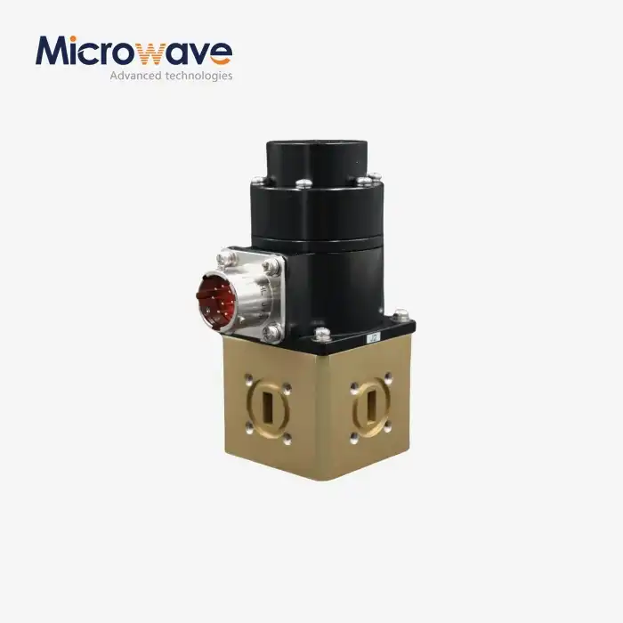 VIEW MOREWaveguide Switch
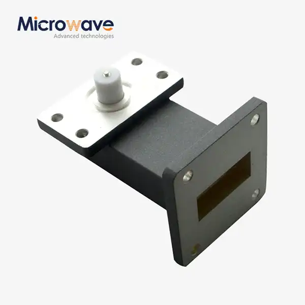 VIEW MORERight Angle Waveguide to Microstrip Adapter
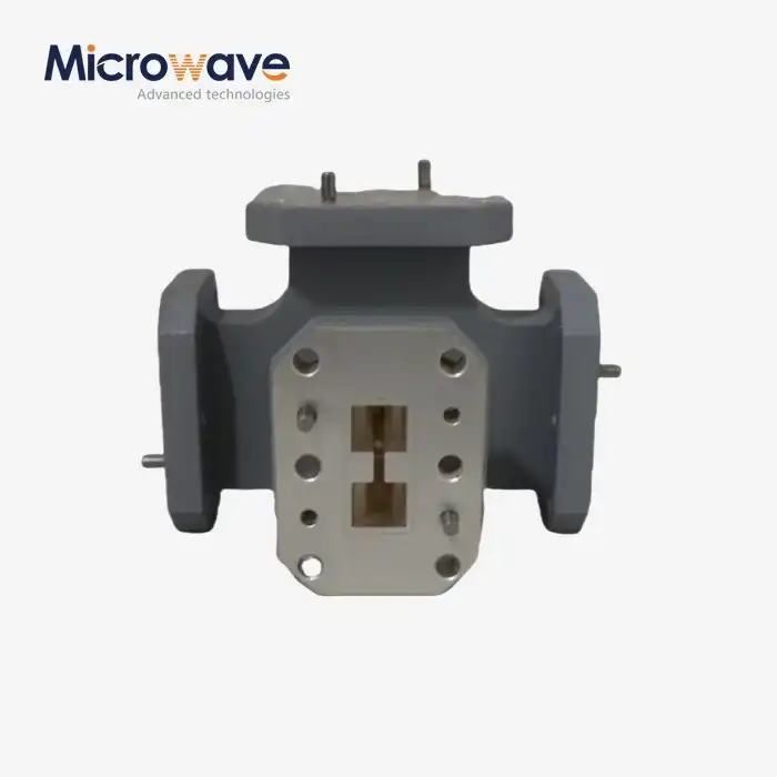 VIEW MOREDouble-Ridged Waveguide Magic Tee
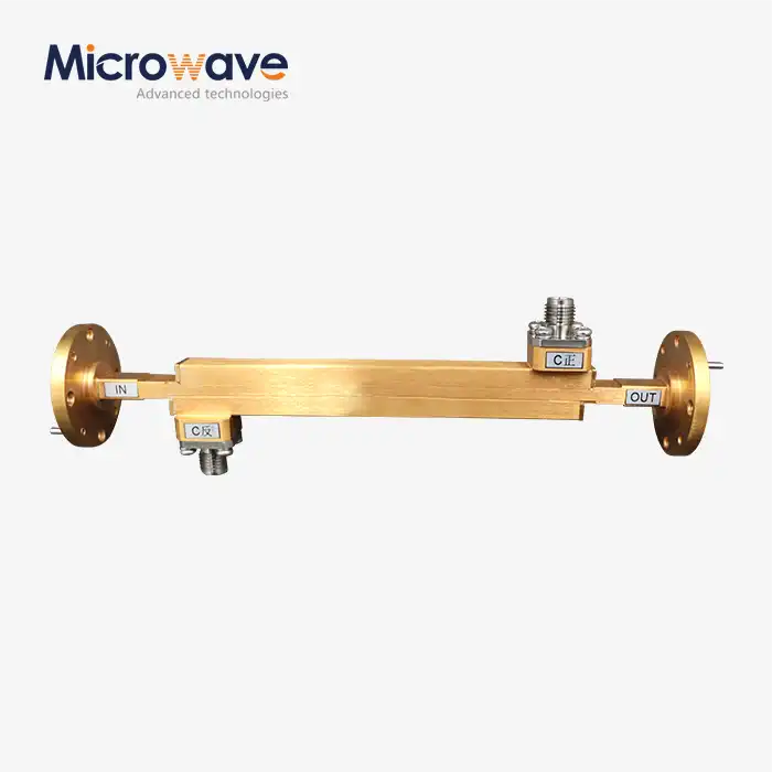 VIEW MOREDouble-Ridged Waveguide Broadwall Directional Coupler
 VIEW MOREAc Power Amplifier
 VIEW MOREDigitally Controlled Phase Shifter
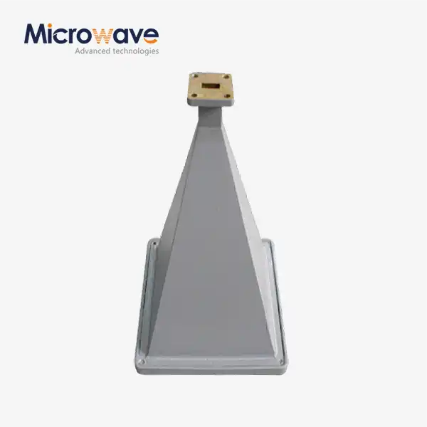 VIEW MOREPyramid Horn Lens Antenna
