


Top RF Rotary Joints for Reliable Satellite Ground Station Connectivity
Maintaining uninterrupted data transmission during antenna rotation is a big engineering problem for satellite ground stations that follow moving satellites across the sky. RF rotary joints solve this issue by sending radio frequency messages between parts that are still and parts that are moving without any loss. In order to ensure signal continuity, the rf rotary joint working principle even during constant 360-degree rotation, the rf rotary joint working principle focuses on keeping precise impedance matching across the rotational interface through specialized coaxial or waveguide connections. These parts are necessary for tracking, radar systems, and satellite communication, where sending signals reliably and with little loss is very important.
Understanding RF Rotary Joints: Basics and Working Principles
The Core Electromagnetic Transfer Mechanism
A complex electromagnetic coupling system moves energy across a spinning surface and is at the heart of every RF rotary joint. The main challenge is to make a communication line that keeps impedance consistency and stops signal loss and reflections that could damage data integrity. This is made possible by channels that are carefully designed to keep their electrical properties fixed, no matter what place they are in the rotational chain. The design makes sure that electromagnetic waves can easily move from the stator, which is fixed, to the rotor, which is spinning. During this transition zone, the characteristic impedance stays the same.
Structural Configurations and Design Elements
A coaxial structure is used in most high-performance rotary joints. This means that an inner conductor turns inside a fixed outer housing, which is held in place by precision bearings that keep the conductors centered. This design keeps the shape of the transmission line, which is important for controlling the resistance. The mechanical design uses special materials with matched thermal expansion factors to keep the parts from getting out of line when the temperature changes, which is common in outdoor ground stations. Sealing systems keep wetness, dust, and harmful substances away from internal parts while still allowing them to rotate smoothly. In high-power situations, waveguide-based rotary joints are better. These devices change signals from waveguide to coaxial, send them through the spinning part, and then change them back to waveguide on the other side. This method can send kilowatt-level power with little insertion loss, which makes it perfect for ground stations that send a lot of power. The conversion stages are designed to keep signal phase stability during rotation and reduce reflections.
Contact Versus Non-Contacting Technologies
Modern RF rotary joints use either coupling mechanisms that involve touch or mechanisms that do not involve contact. Contact designs use brushes or contact points made of valuable metals that keep the electrical link strong while the design turns. Even though they work very well electrically, they need to be serviced every so often to fix wear. Capacitive or electromagnetic coupling across small air gaps is used in non-contacting designs to stop mechanical wear and increase operating life beyond 50 million spins. Which of these models to use depends on the needs of the application. Usually, satellite ground stations choose non-contacting RF rotary joint working principle designs because they are more reliable and require less upkeep.

Comparing RF Rotary Joints with Alternative Rotary Solutions
Electrical Slip Rings: Limitations at High Frequencies
Electrical slip rings work well with power and low-frequency signals, but they have a lot of problems when used with radio frequency communications. Their contact-based design adds electrical noise, changes in resistance, and signal loss that become a problem above a few megahertz. As the contact resistance changes during spinning, amplitude modulation effects happen that mess up critical satellite telemetry data. At microwave frequencies, slip rings also have bad voltage standing wave ratio (VSWR) properties. This causes power to be mirrored, which lowers the efficiency of the system and can hurt sensitive sensor parts.
Fiber Optic Rotary Joints: Different Application Domains
Fiber optic rotary joints are great at sending digital data streams across moving surfaces, but they are not at all like RF rotary joints. They change electrical signals into optical signals, send them through spinning fiber links, and then change the optical signals back to electrical ones. This method protects against electromagnetic interference and allows for very fast data rates, but it adds delay, needs power for optical transceivers, and can't directly handle RF analog signals. Most of the time, satellite ground stations use both technologies together. Fiber optics is used for digital control and monitoring, while RF rotary joints are used for analog signal paths and high-power transfer.
RF Rotary Joints: Specialized Advantages
RF rotary joints are the only ones that can handle the needs of sending high-frequency analog signals across moving surfaces. They keep the phase coherence needed for carrier tracking, the signal amplitude stability needed for accurate data, and the ability to handle both the receive and send paths at the same time with multi-channel designs. Their frequency response goes from UHF to Ka-band and beyond, which is the whole range of frequencies used for satellite transmission. Environmental stability lets it work in temperatures ranging from -55°C to +85°C and in harsh weather conditions common for ground stations that are set up outside. Because of these unique skills, they are the world's leading provider of satellite tracking antenna devices.
Top RF Rotary Joint Models for Satellite Ground Station Applications
High-Performance Coaxial Rotary Joints
Coaxial rotary joints made by top makers are perfect for frequency rf rotary joint working principle bands used by satellite base stations. In the C-band (4-8 GHz) and X-band (8-12 GHz) models, the insertion loss is less than 0.3 dB, and the VSWR is better than 1.15:1. These requirements make sure that the signal weakens as little as possible during satellite passes, which protects link budget gaps. Multichannel setups let you send and receive data at the same time, and they isolate channels by more than 60 dB to stop noise. Electrical performance is kept up for millions of spinning cycles thanks to precise drilling and controlled assembly processes. Field deployment statistics from major satellite providers show that the average time between breakdowns is more than 15 years when the system is running continuously.
Waveguide Rotary Joints for High-Power Applications
Waveguide rotary joints that can handle kilowatts of RF power are used by ground stations that allow high-power uplink broadcasts. These strong parts have rectangular waveguide connectors that work with common radio feed systems. Precision-aligned waveguide transitions in the spinning part keep the insertion loss low (usually 0.5 dB) while handling peak powers of more than 10 kW. Forced air cooling ducts and heat-dissipating materials are examples of thermal management features that keep performance from dropping during long transmission periods. Operators of satellites that use these systems say they work reliably in tough situations, like military SATCOM networks and communications in deep space.
Dual-Band and Broadband Solutions
Multi-band rotary joint systems are needed because modern satellite ground stations often work on more than one frequency band at the same time. Modern designs use coaxial structures that work best in a wide range of frequencies, from L-band to Ku-band (1-18 GHz), all in a single, small package. These rotary joints make it possible to track multiple satellites at the same time or support different satellite transmission standards without having to switch bands mechanically. Performance proof tests show that the electrical properties are the same across the whole frequency range, and the phase stability is better than ±5 degrees when the device is turned. System designers say that using these flexible parts saves them a lot of money and makes antennas simpler.
How to Choose and Procure the Right RF Rotary Joint for Your Satellite Ground Station
Evaluating Critical Performance Specifications
Before choosing the right RF rotary joint, it's important to carefully look over what the system needs. The frequency range needs to cover all working bands with a safe buffer, which is usually 10–20% beyond the edges of the nominal bands. Insertion loss has a direct effect on link budget; for every 0.1 dB of extra loss, effective antenna gain goes down by the same amount. Instead of asking for average values, procurement teams should ask for promised maximum insertion loss figures. This way, even in the worst case, performance will still be okay. Specifications for VSWR show how well the impedances match; numbers below 1.20:1 are common for expert ground station use. For carrier tracking systems to work, phase stability during rotation is very important. Usually, standards call for changes of less than ±3 degrees across a full 360-degree turn. Power handling must be higher than maximum send power by an acceptable amount to keep parts from breaking and to ensure long-term dependability. Peak power, not just normal power, should be taken into account in pulsed uses. The temperature range you specify must include the extremes of the area where you are installing it, including the effects of the sun's heat on antenna-mounted parts. To give you enough practical headroom, the rotational speed values should be at least 50% higher than your antenna slew rates.
Supplier Evaluation and Quality Assurance
Suppliers you can trust give you detailed scientific information that includes performance data that was tested over the whole frequency range that was asked for. Detailed technical sketches make planning the connection easier and show what mounting needs to be done. Professionals in charge of buying things should make sure that the company is certified under ISO 9001 and ask for proof that quality control measures were taken during production. Suppliers that can test up to 110 GHz in-house show that they are very good at technology and can provide proof of plant acceptance testing. Referrals from current users of satellite ground stations are a great way to find out about the quality of long-term dependability and after-sales support.
Customization Capabilities for Unique Requirements
Catalog goods that are standard meet most needs, but many ground station users need solutions that are specifically made for them. Some of the best makers offer engineering services that can change the designs of rotary joints to work with certain frequency bands, power levels, or mechanical connections. To make system integration easier, you can ask for custom waveguide flanges, mounting setups, and multi-channel arrangements. During the system creation steps, being able to quickly rf rotary joint working principle to make prototypes of custom designs is useful. Talking about your specific needs with expert teams with a lot of experience can often lead to better solutions that boost speed while lowering the overall cost of the system. Before deciding to buy something, you should think about how much long-term upkeep will cost and whether extra parts are available. Lifecycle costs are lower for parts that can be maintained in the field and have wear parts that are easy to find than for protected units that need to be replaced completely. When problems happen, warranty terms and how quickly technical help responds have a big effect on how smoothly operations can continue. Building partnerships with makers that offer full support, such as installation advice, troubleshooting help, and performance verification services, is a good way to protect mission-critical satellite ground station operations.
Future Trends and Innovations in RF Rotary Joint Technology
Advanced Materials Enhancing Performance
New material technologies have the potential to make RF rotary joints much better. Low-loss dielectric materials that keep their electrical properties steady at high and low temperatures allow for wider bandwidth operation with less insertion loss. New bearing materials with low friction and long wear resistance allow for faster turning speeds while still keeping the bearings precisely aligned. Corrosion-resistant metals and improved coatings make things last longer in harsh marine and seaside settings where salt spray speeds up the breakdown of parts. These material innovations directly fix problems that have been around for a long time, making it possible for next-generation ground station designs.
Integration with Smart Monitoring Systems
In the future, RF rotary joints will have built-in sensors and testing tools that will let you see how they're working in real time and get maintenance alerts before they break. Strain gauges find mechanical stress, temperature monitors find strange changes in temperature, and electrical tracking circuits keep an eye on VSWR and insertion loss while the system is running. This information is sent to control systems at the ground station through built-in connections. This lets condition-based repair plans stop problems before they affect operations. Early users of these smart parts say that unplanned downtime and repair costs have gone down a lot.
Millimeter-Wave and 5G Satellite Applications
As satellite communications grow into the Ka-band (26-40 GHz) and new Q/V-band (40-75 GHz) bands, rotary joints that can handle these higher frequency ranges are being made. At millimeter wavelengths, where electrical performance is determined by dimensional limits measured in micrometers, manufacturing quality needs to be much higher. Precision CNC machining and additive manufacturing are two examples of advanced manufacturing techniques that make it possible to make complex internal shapes that improve signal transfer at these difficult frequencies. These new rotary joint technologies will be important for ground sites that serve 5G satellite backhaul and high-throughput transmission satellites.
Conclusion
RF rotary joints are an important piece of technology for satellite ground stations because they allow signals to be sent continuously across spinning antenna connections. Procurement experts can choose the best options for their systems if they understand the basic working principles, performance characteristics, and application-specific criteria. The technology keeps getting better with new materials, smart tracking tools, and wider frequency coverage that supports the designs of the next generation of satellite communications. Partnering with experienced makers that offer full technical support, the ability to make changes, and a track record of stability is the best way to ensure long-term operating success in mission-critical applications.
FAQ
What is the typical operational lifespan of an RF rotary joint in continuous satellite tracking applications?
RF rotary joints made for satellite ground stations that are of good quality usually last more than 50 million rotations. In constant tracking activities that last an average of 4 to 6 hours a day, this means that it will work reliably for 15 to 20 years before it needs to be serviced. Because they don't wear down mechanically, non-contacting designs usually last longer than contact-based ones. The actual lifespan relies on how often it is used, the environment, and whether or not the manufacturer's upkeep suggestions are followed. Following the manufacturer's instructions for regular cleaning and lubrication will extend the service life.
How can signal loss during rotation be minimized in RF rotary joint installations?
Paying close attention to a number of things during design and installation is needed to keep signal loss to a minimum. The first step is to choose rotary joints that have proven low insertion loss specs that are right for your frequency band. Making sure that the rotary joint and the transmission lines that are linked have the same resistance stops reflections that raise the effective loss. Signal path losses are kept to a minimum by using high-quality RF connections and short wire lengths. Deterioration over time can be stopped by making sure the installation is properly aligned and checking the technical state on a regular basis. Protecting the environment, such as by weatherproofing, stops water from getting in, which can lead to more losses.
Can RF rotary joints be customized for specialized frequency bands or environmental requirements?
Reliable makers offer a wide range of customization options to meet the specific needs of each application. To fit different ground station designs, engineers can make waveguide flanges with custom frequency bands, multi-channel setups, and mounting connections that are a better fit for those stations. You can make materials harder in harsh environments with high humidity, high temperatures, or toxic gases by choosing the right materials and improving the way they close. Usually, the customization process starts with in-depth technical talks to describe needs. This is followed by engineering design, making a sample, and testing it to make sure it works properly. Custom patterns usually take between 8 and 16 weeks to make, but this depends on how complicated they are.
Partner with ADM for High-Performance RF Rotary Joint Solutions
Advanced Microwave Technologies Co., Ltd. (ADM) has been developing rf rotary joint working principle and making precise RF parts for satellite ground stations and mission-critical communication systems for more than 20 years. With a deep understanding of the complex needs of satellite tracking applications, our engineering team can help you choose or customize RF rotary joint solutions that work best for your unique needs. We provide parts that meet the high-performance standards needed by defense, military, and commercial satellite users around the world. Our products are backed by ISO 9001:2015 quality certification and advanced testing powers up to 110 GHz. Our fast technical support team and efficient production processes make sure that you get what you need quickly without sacrificing quality, whether you need standard catalog items or fully customizable rotary joint assemblies. As a seller of RF rotary joints with a lot of experience, we keep our prices low by managing our supply chain efficiently and offering full after-sales support to ensure long-term operating success. Email our buying experts at craig@admicrowave.com to talk about your satellite ground station needs and get specific technical advice that fits your situation.
References
1. Johnson, R.C., "Antenna Engineering Handbook," Fourth Edition, McGraw-Hill Professional, 2007, Chapter 42: Rotary Joints and RF Connectors for Rotating Antenna Systems.
2. Skolnik, M.I., "Radar Handbook," Third Edition, McGraw-Hill Education, 2008, Section 14.5: Rotary Joint Design for Tracking Radar Antennas.
3. Balanis, C.A., "Modern Antenna Handbook," John Wiley & Sons, 2008, Chapter 8: RF Transmission Components for Satellite Ground Stations.
4. IEEE Standard 149-2021, "IEEE Recommended Practice for Antenna Measurements," Institute of Electrical and Electronics Engineers, Section 6.4: Rotary Joint Considerations in Antenna Testing.
5. Macnamara, T., "Introduction to Antenna Placement and Installation," John Wiley & Sons, 2010, Chapter 11: RF Distribution Systems and Rotary Joints in Tracking Antennas.
6. Global Satellite Ground Station Equipment Market Report 2023, Markets and Markets Research, Technical Component Analysis: RF Rotary Joint Performance Requirements and Selection Criteria.
YOU MAY LIKE
 VIEW MOREDouble Ridge Straight Waveguide
 VIEW MOREDouble Ridge Waveguide Transition
 VIEW MOREDouble Ridged Flexible Waveguide
 VIEW MOREDouble Ridge Waveguide Load
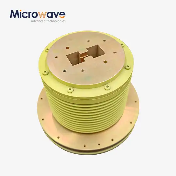 VIEW MOREDouble Ridge Waveguide Rotary Joint
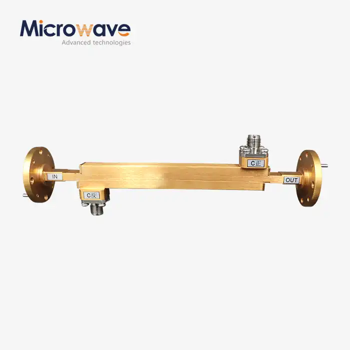 VIEW MOREDouble-Ridged Waveguide Broadwall Directional Coupler
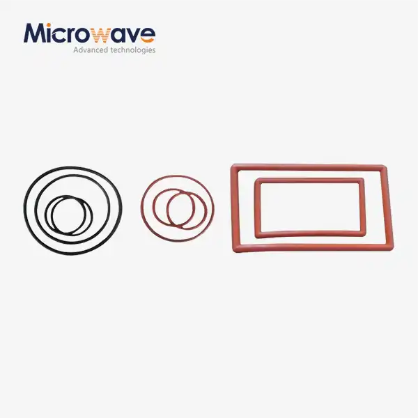 VIEW MOREWaveguide Flange Gasket
 VIEW MOREWaveguide Adjustable Support
