5 differences between directional couplers and taps
In modern RF and microwave systems, selecting the right signal distribution component can mean the difference between seamless performance and catastrophic signal loss. Engineers frequently face critical decisions when designing satellite ground stations, distributed antenna systems, or radar installations—should they deploy a Coaxial Directional Coupler or opt for a tapper? This confusion leads to costly system redesigns, compromised signal integrity, and performance bottlenecks that could have been avoided with proper component selection. Understanding the five fundamental differences between directional couplers and taps empowers system designers to make informed choices that optimize insertion loss, frequency response, and directional isolation while ensuring their RF distribution network delivers maximum efficiency across demanding applications from defense surveillance to 5G telecommunications infrastructure.
Power Splitting Architecture: Asymmetric vs Symmetric Distribution
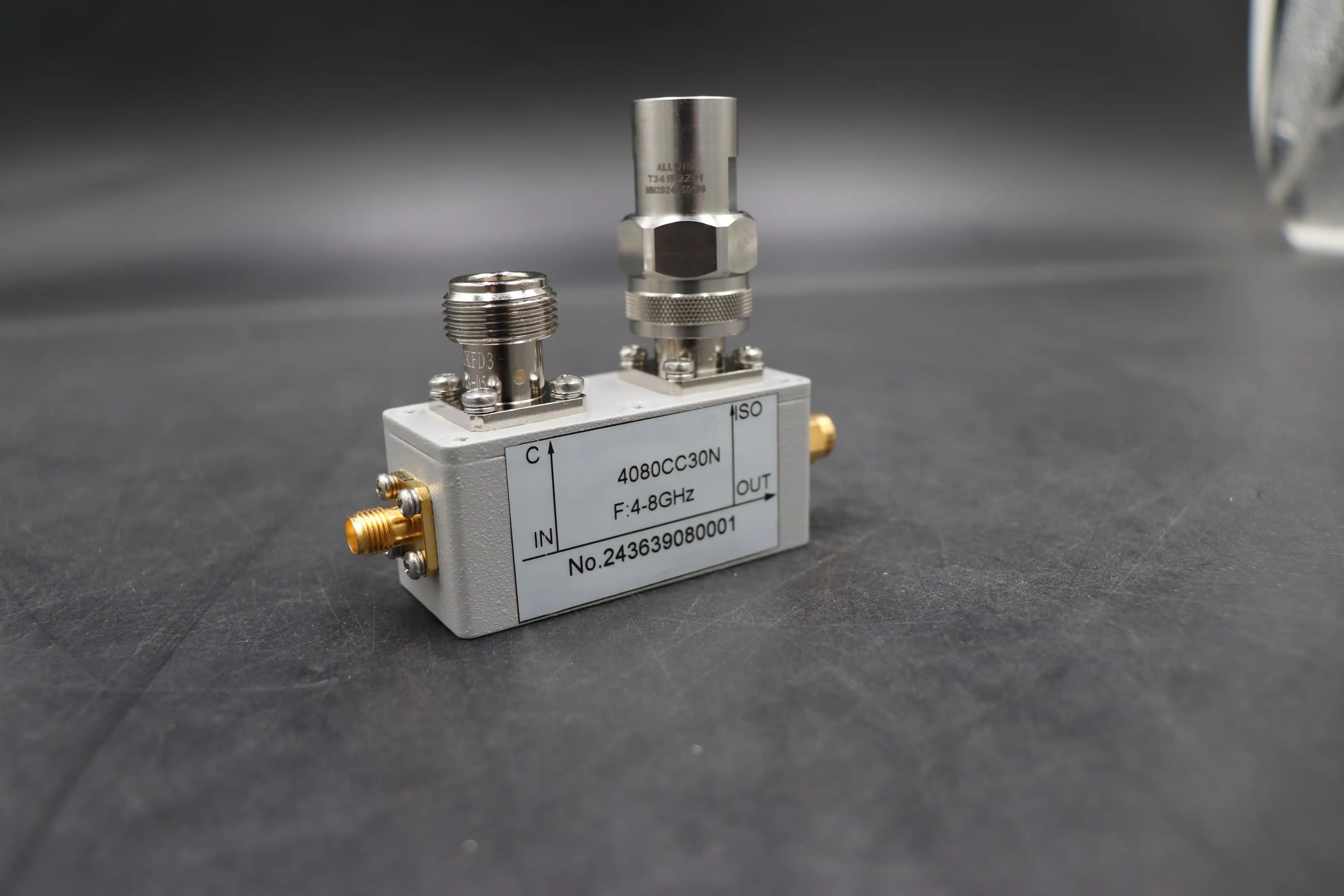
The fundamental distinction between directional couplers and taps lies in their power distribution philosophy. A Coaxial Directional Coupler operates on an asymmetric principle, where the main transmission line carries the vast majority of signal power—typically ninety to ninety-nine percent—while the coupled port samples only a small fraction, ranging from one to ten percent of the input signal. This design ensures minimal disturbance to the primary signal path, making it ideal for applications requiring signal monitoring without significant power extraction. For instance, a ten-decibel Coaxial Directional Coupler allows ninety percent of the power to continue forward along the main line while diverting precisely ten percent to the coupled port for measurement or feedback purposes. In stark contrast, taps function as symmetric or near-symmetric power dividers, distributing signal energy more evenly across multiple output ports. Common tap configurations include two-way splits delivering fifty percent to each port, three-way divisions providing approximately thirty-three percent per output, or four-way arrangements allocating twenty-five percent to each branch. This equal distribution architecture serves different system requirements, particularly in distributed antenna systems where multiple remote units require comparable signal levels. The physics behind this difference stems from the coupling mechanism itself—Coaxial Directional Couplers utilize electromagnetic field coupling through carefully engineered stripline or waveguide structures that extract a controlled portion of energy without significantly impeding the main signal flow, whereas taps employ resistive or capacitive coupling networks that inherently create more substantial power division.
Impact on Insertion Loss Performance
The architectural differences between these components directly translate into dramatically different insertion loss characteristics that critically impact system design. When a Coaxial Directional Coupler is inserted into a transmission line, it introduces minimal disruption to the primary signal path, typically adding only zero-point-one to zero-point-five decibels of insertion loss. This remarkably low loss factor means that in a twenty-decibel directional coupler installation, approximately ninety-nine percent of the input power successfully reaches the output port, with only one percent extracted for monitoring or control functions. This efficiency proves essential in high-power transmitter applications, satellite uplink systems, and precision test equipment where every fraction of a decibel matters for system performance. Taps, however, impose substantially higher insertion loss penalties due to their power-splitting nature. A basic two-way tap configuration introduces a minimum three-decibel loss per output port, effectively halving the signal power even before accounting for component inefficiencies. When multiple taps are cascaded in series—a common scenario in distributed antenna systems or cable television distribution networks—the cumulative loss compounds rapidly. Consider a practical example where three two-way taps are chained together to serve multiple coverage zones: the resulting nine-decibel total insertion loss reduces the original signal strength to merely twelve-point-five percent of its initial power level, necessitating additional amplification stages that increase system complexity, cost, and potential noise figure degradation.
Port Configuration and Directivity Characteristics
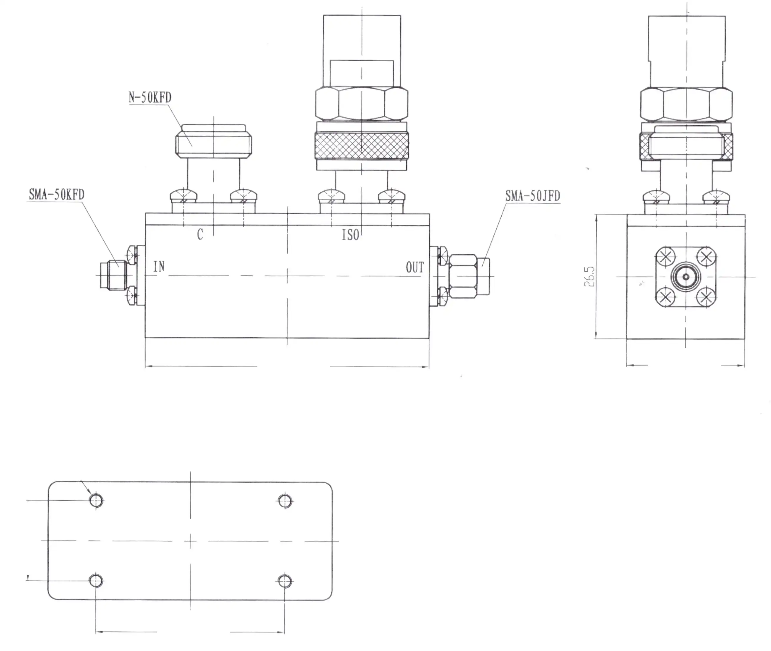
Coaxial Directional Couplers feature a sophisticated four-port architecture designed to provide exceptional signal routing control and isolation. The input port receives the primary RF signal, which then propagates to the output or through port with minimal attenuation. Simultaneously, the coupled port extracts a precisely calibrated sample of the forward-traveling wave, while the isolated port—terminated with a matched fifty-ohm or seventy-five-ohm load—absorbs any reflected energy and backward-traveling signals. This directional selectivity represents one of the most valuable characteristics of Coaxial Directional Couplers, enabling engineers to distinguish between forward and reverse power flow, measure return loss accurately, and implement sophisticated feedback control systems in transmitter applications. The isolation specification of premium Coaxial Directional Couplers often exceeds thirty decibels, meaning that power entering the isolated port is attenuated by more than one-thousand-fold relative to the main signal path. This extraordinary isolation capability prevents unwanted signal interactions, reduces measurement uncertainty, and enables multiple directional couplers to operate in proximity without crosstalk interference. Advanced models operating at millimeter-wave frequencies up to one-hundred-ten gigahertz incorporate precision-machined waveguide structures and high-performance connectors such as SMA or 2.92-millimeter types to maintain this isolation across extreme bandwidth ranges.
Tapper Port Architecture and Limitations
Tappers typically implement a simpler three-port configuration consisting of one input and two or more output ports, with no dedicated isolated port. This simplified architecture reduces manufacturing complexity and cost but sacrifices the directional selectivity that defines true Coaxial Directional Couplers. The absence of directivity means that tappers cannot distinguish between forward and backward traveling signals—power entering any port distributes across all other ports according to the device's coupling ratio, regardless of signal propagation direction. While this bidirectional characteristic proves acceptable for certain distributed antenna system applications where signal flow is predominantly unidirectional, it creates significant challenges in applications requiring precise signal monitoring, return loss measurement, or transmit-receive isolation. The port impedance matching of tappers also presents practical considerations that distinguish them from precision Coaxial Directional Couplers. While high-quality directional couplers maintain consistent fifty-ohm or seventy-five-ohm impedance across all ports to minimize voltage standing wave ratio and maximize power transfer efficiency, lower-cost taps may exhibit impedance variations ranging from sixty to eighty ohms under loaded conditions. These impedance mismatches introduce additional return loss of one-point-five to two decibels, further degrading overall system performance and potentially causing signal reflections that interfere with sensitive receiver circuits or compromise transmitter stability in full-duplex communication systems.
Frequency Response and Bandwidth Capabilities
The frequency response characteristics of Coaxial Directional Couplers versus taps reveal another critical distinction that influences component selection for specific applications. Premium Coaxial Directional Couplers demonstrate exceptional wideband performance, with frequency ranges extending from five-hundred megahertz to forty gigahertz becoming standard offerings, while specialized models for millimeter-wave research applications push operational limits to one-hundred-ten gigahertz. This remarkable bandwidth capability stems from the distributed-element design philosophy employed in directional coupler construction, where coupled transmission line sections or waveguide structures inherently scale their electromagnetic behavior proportionally with frequency. The coupling mechanism remains relatively stable across multiple octaves of bandwidth, maintaining consistent coupling factor, insertion loss, and isolation specifications throughout the operating range. This ultra-broadband performance makes Coaxial Directional Couplers indispensable for applications spanning multiple frequency bands simultaneously, such as fifth-generation wireless base stations operating across sub-six-gigahertz and millimeter-wave spectrum allocations, multi-band satellite communication ground terminals, and advanced radar systems requiring simultaneous operation in X-band, Ku-band, and Ka-band frequencies. The test equipment sector particularly values this wideband characteristic, as network analyzers, spectrum analyzers, and automated test systems rely on Coaxial Directional Couplers to provide accurate signal sampling across instrument measurement ranges that may span from direct-current to fifty gigahertz or beyond.
Tapper Frequency Limitations and Roll-off
Tappers, particularly those based on lumped-element resistive or capacitive coupling networks, exhibit markedly narrower useful bandwidth compared to distributed-element Coaxial Directional Couplers. Typical resistive tappers designed for cable television distribution or basic distributed antenna system applications maintain acceptable performance across five megahertz to one-thousand megahertz, with some models extending operational range to six gigahertz under ideal conditions. However, low-cost implementations frequently begin exhibiting significant performance degradation above two gigahertz, manifesting as increased coupling ripple of three decibels or more, reduced port-to-port isolation, and unpredictable phase response that compromises signal integrity in digital communication systems. The fundamental limitation arises from the lumped-element construction of many tap designs, where discrete resistors, capacitors, or coupled segments behave predictably at lower frequencies but develop parasitic reactances at higher frequencies that transform these components into inefficient radiating structures rather than controlled coupling elements. Attempting to deploy a five-dollar cable television splitter rated for five to one-thousand megahertz operation in a twenty-eight-gigahertz fifth-generation millimeter-wave test setup results in catastrophic signal loss exceeding twenty decibels, with virtually all input power dissipated as heat or radiated as electromagnetic interference rather than transferred to the intended output ports. For applications requiring reliable multi-octave bandwidth performance, particularly those involving frequencies above three gigahertz, Coaxial Directional Couplers represent the technically sound choice despite their higher initial cost compared to basic tappers.
Application-Specific Performance Optimization
Coaxial Directional Couplers excel in applications demanding high measurement accuracy, precise signal monitoring, and robust directional isolation. In satellite ground station installations, these components enable real-time monitoring of transmitter forward power and reflected power simultaneously, allowing automatic fault detection and protection systems to respond within microseconds to antenna mismatches or transmission line failures that could damage expensive high-power amplifiers. The exceptional isolation specification of advanced Coaxial Directional Couplers—often exceeding thirty-five decibels—ensures that coupled port measurements remain accurate even when measuring low-level reflected signals in the presence of kilowatt-level forward power, a critical capability for optimizing satellite uplink performance and ensuring regulatory compliance with equivalent isotropically radiated power limitations. Defense and aerospace applications leverage the precision characteristics of Coaxial Directional Couplers in phased array radar systems, where individual transmit-receive modules require accurate power monitoring for beam steering calibration and electronic warfare countermeasure effectiveness assessment. The wide frequency coverage from direct-current to one-hundred-ten gigahertz accommodates both legacy radar modernization programs operating in established frequency bands and cutting-edge systems exploiting millimeter-wave spectrum for enhanced resolution and target discrimination. Advanced Microwave Technologies Co., Ltd. manufactures Coaxial Directional Couplers with coupling values of ten decibels, twenty decibels, and thirty decibels to address diverse monitoring requirements, while maintaining insertion loss specifications below zero-point-two decibels and voltage standing wave ratio below one-point-two-to-one across the entire operational bandwidth.
Tapper Deployment in Distributed Systems
Tappers find their optimal application niche in distributed antenna system architectures where cost-effective signal distribution to multiple remote antenna units takes priority over measurement precision and directional isolation. Indoor coverage systems for commercial buildings, public safety communication networks, and wireless internet service provider deployments commonly employ cascaded tapper chains to deliver acceptable signal levels to dozens of antenna locations while minimizing active component count and power consumption. The lack of directivity in tappers becomes less problematic in these scenarios because the system topology inherently provides signal flow primarily in one direction—from the base station or repeater toward the remote antennas—with uplink signals captured by individual antennas naturally combining at the baseband processing unit without requiring precise isolation between paths. The economic advantage of tappers becomes compelling when deploying large-scale distributed antenna systems covering extensive facility areas such as airport terminals, convention centers, or underground transportation networks. A typical installation might incorporate twenty to fifty tapper locations, where the cost differential between resistive tappers and precision Coaxial Directional Couplers could amount to tens of thousands of dollars in component procurement alone, not accounting for the simplified installation procedures and reduced testing requirements associated with the more forgiving performance specifications of tap-based distribution networks. However, system designers must carefully analyze the cumulative insertion loss through cascaded tapper chains and provision adequate amplification stages to maintain required signal-to-noise ratio at the most distant coverage points, as the three-decibel per-stage loss of tappers accumulates rapidly across multi-hop distribution trees.
Technical Specifications and Performance Parameters
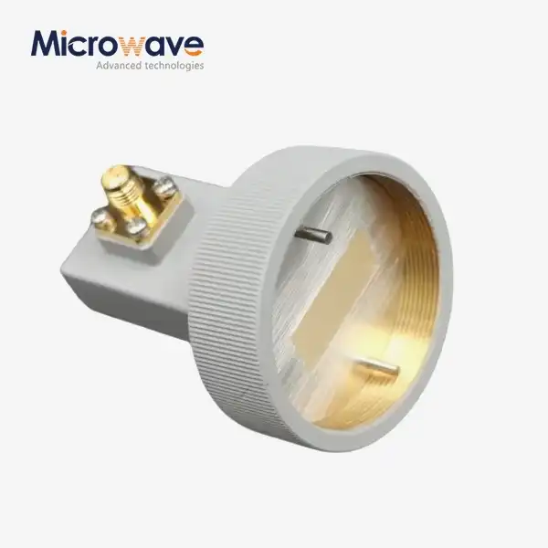
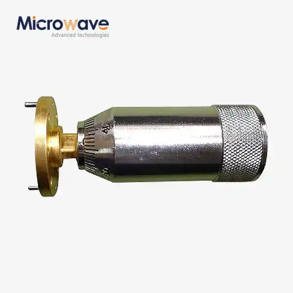
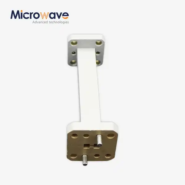
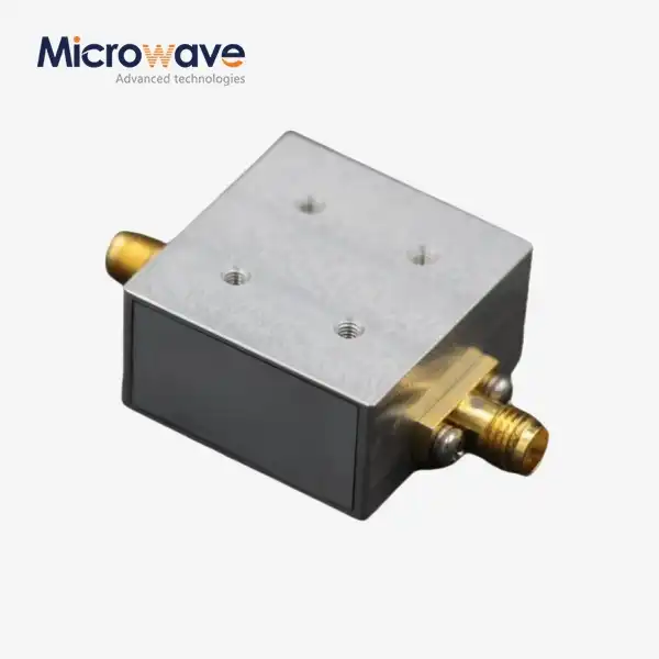
Advanced Microwave Technologies Co., Ltd. manufactures a comprehensive line of Coaxial Directional Couplers engineered to meet the demanding requirements of modern satellite communications, defense systems, aerospace projects, and telecommunications infrastructure. Our product portfolio spans frequency ranges from direct-current to one-hundred-ten gigahertz, addressing applications from baseband signal processing through millimeter-wave experimental systems. Standard coupling values of ten decibels, twenty decibels, and thirty decibels accommodate diverse signal sampling requirements, from high-level power monitoring in transmitter output stages to sensitive measurement applications requiring minimal signal extraction to preserve measurement accuracy. Power handling capabilities extending to five-hundred watts continuous wave operation enable deployment in high-power broadcast, radar, and electronic warfare applications without component derating or thermal management concerns. The exceptional electrical performance of our Coaxial Directional Couplers stems from rigorous design optimization and precision manufacturing processes. Insertion loss specifications of zero-point-two decibels or less ensure that signal power reaches its intended destination with minimal degradation, critical for maximizing transmitter effectiveness and receiver sensitivity in communication systems operating at the limits of link budget margins. Voltage standing wave ratio maintained at one-point-two-to-one or better guarantees efficient power transfer and minimizes signal reflections that could compromise measurement accuracy or create standing wave patterns degrading system performance. Isolation exceeding thirty decibels between coupled and isolated ports enables accurate bidirectional power measurement and sophisticated signal routing applications. Mechanical construction utilizing aerospace-grade aluminum or corrosion-resistant stainless steel housings with precision SMA, N-type, or customer-specified connectors ensures long-term reliability in harsh environmental conditions ranging from arctic installations to tropical maritime environments.
Quality Assurance and Manufacturing Excellence
Our state-of-the-art twenty-four-meter microwave darkroom facility enables comprehensive antenna and component testing across the complete zero-point-five to one-hundred-ten-gigahertz frequency range, ensuring every Coaxial Directional Coupler leaving our production facility meets or exceeds published specifications. The Antenna Plane Near and Far Field Measuring Recombination Chamber allows our engineering team to characterize radiation patterns, coupling accuracy, and port-to-port isolation with unprecedented precision, identifying performance variations that might escape detection in conventional test setups. This measurement capability, combined with our ISO nine-thousand-one-colon-two-thousand-eight quality certification and RoHS environmental compliance, provides customers with the confidence that Advanced Microwave Technologies Co., Ltd. Coaxial Directional Couplers will deliver consistent, reliable performance throughout their operational lifetime. Our manufacturing processes incorporate stringent quality control checkpoints at every production stage, from raw material inspection through final electrical and mechanical testing. Each Coaxial Directional Coupler undergoes automated network analyzer testing to verify insertion loss, coupling factor, isolation, and return loss across the specified frequency range, with test data archived for traceability and warranty support. Environmental stress screening including thermal cycling and vibration testing validates mechanical integrity and electrical stability under conditions exceeding typical field deployment scenarios. This comprehensive quality assurance program ensures that when you specify a China Coaxial Directional Coupler from Advanced Microwave Technologies Co., Ltd., you receive a component that performs precisely as expected, whether installed in a satellite earth station operating continuously for twenty years or deployed in a military radar system subjected to extreme temperature variations and mechanical shock.
Conclusion
Understanding the five fundamental differences between directional couplers and taps empowers engineers to select optimal components for specific applications. Coaxial Directional Couplers provide superior isolation, minimal insertion loss, and wideband performance essential for precision measurements, while tappers offer economical signal distribution for distributed antenna systems.
Cooperate with Advanced Microwave Technologies Co., Ltd.
Advanced Microwave Technologies Co., Ltd. stands ready to support your next RF and microwave project with over twenty years of manufacturing excellence and comprehensive engineering expertise. As a leading China Coaxial Directional Coupler manufacturer and China Coaxial Directional Coupler supplier, we deliver high-quality Coaxial Directional Couplers backed by ISO nine-thousand-one-colon-two-thousand-eight certification and RoHS compliance. Our China Coaxial Directional Coupler factory produces components for sale with competitive Coaxial Directional Coupler prices without compromising reliability or performance. Whether you need standard catalog items for immediate delivery or custom OEM solutions tailored to unique frequency ranges, power handling requirements, or mechanical form factors, our technical team collaborates closely with customers to develop optimal solutions. Request a quotation today for high quality Coaxial Directional Coupler wholesale pricing and discover how our advanced testing capabilities, efficient production processes, and responsive customer support transform your microwave system designs from concept to reality. Contact craig@admicrowave.com to discuss your specific requirements with our applications engineering specialists and experience the Advanced Microwave difference.
References
1. Matthaei, G. L., Young, L., & Jones, E. M. T. (1980). Microwave Filters, Impedance-Matching Networks, and Coupling Structures. Artech House Publishers.
2. Pozar, David M. (2011). Microwave Engineering, Fourth Edition. John Wiley & Sons, Inc.
3. Rizzi, Peter A. (1988). Microwave Engineering: Passive Circuits. Prentice Hall International Editions.
4. Vendelin, George D., Pavio, Anthony M., & Rohde, Ulrich L. (2005). Microwave Circuit Design Using Linear and Nonlinear Techniques, Second Edition. John Wiley & Sons, Inc.


