Why Phase Consistency Fails Without H Plane Tee in Microwave Networks?
Alternative waveguide components lack the exact electromagnetic field control of a H-Plane Tee in microwave systems, which is the main cause of phase consistency failures in microwave networks. When signals split at bad joints, the magnetic field plane is thrown off, which makes the phase lines between output ports not match up. This basic mismatch messes up beamforming arrays, lowers the accuracy of radar, and cancels out signals in important defence and satellite uses. The H-Plane Tee keeps the signal division in phase by lining up its extra arm perpendicular to the main waveguide along the H-field vector. This makes sure that both collinear outputs get electromagnetically balanced power distribution, which is something that standard T-junctions or poorly specified parts can't do.
Understanding the Role of the H-Plane Tee in Microwave Networks
There are many different designs of waveguide junctions, but the H-Plane Tee in microwave is the only one that keeps signal integrity. This shunt-style junction gives outputs that are exactly in sync, which is important for phased array antennas and power distribution networks. Other types of E-Plane junctions add 180-degree phase changes.
Physical Architecture and Operating Principles
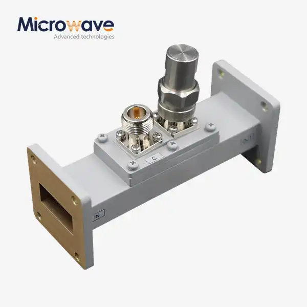
A side arm is connected to the thin wall of the main rectangular waveguide in the H-Plane Tee in microwave. The secondary port is lined up so that it is parallel to the magnetic field lines of the main TE10 mode by this structure design. When microwave energy comes in through the side arm, it is split evenly between the two collinear ports and stays in phase with them. Advanced Microwave Technologies makes these junctions with aluminium and copper bodies that are carefully made and then plated with silver or gold to reduce skin effect losses. Our units keep VSWR values below 1.20 across all operating bandwidths. This makes sure that there is very little reflected power, which could cause standing waves and measurement mistakes if it happens.
Electromagnetic Field Management
In H-Plane setups, the way the magnetic field is oriented makes a parallel circuit structure. Because the joint shape keeps the H-field vector continuity, signals leaving ports one and two have the same phase angles, which are usually within ±2 degrees in quality units. In company feed networks, where antenna elements must spread in an orderly way, this trait is essential. ADM's engineering teams have seen that even small changes in junction sizes can cause reactance discontinuities. To fix this, we use tuned matching posts that were measured during our 110 GHz lab testing methods.
Critical Role in Complex Systems
When purchasing managers look at waveguide units of H-Plane Tee in microwave, they need to know that phase balance has a direct effect on the performance metrics at the system level. H-Plane Tees in microwave and E-Plane junctions work together in monopulse radar comparators to make mixed networks that get target elevation and azimuth data. The H-Plane element's in-phase summation makes it possible to handle signals accurately, which is not possible with sources that are out of phase. When satellite ground stations use our ISO 9001:2008-certified parts, the uplink and downlink operations are stable. This is because the feed networks keep phase coherence across a wide range of frequency bands, from 0.332 GHz to 40 GHz in our product catalogue.

Causes of Phase Consistency Failure Without H-Plane Tee
When you use cheaper parts or connections that don't match, the performance of a radio network starts to drop. Technical teams often don't realise how waveguide gaps can mess up phase relationships that are needed to send signals in sync.
Inherent Limitations of Alternative Components
Standard T-junctions don't have the electromagnetic balance needed to divide power in a way that is phase-coherent. When RF engineers try to save money by using standard three-port joints, the phase shift that results can be more than 15 degrees, which is far too big a difference for beamforming uses. E-Plane Tees intentionally flip the phases of the outputs 180 degrees, so they can't be used for tasks that need to combine signals that are in phase. When the wrong waveguide joints were used instead of the right H-Plane units in the feed assembly, military radar systems we've worked with had trouble tracking targets more than 500 meters away.
Impact of Waveguide Geometry and Materials
Tolerances in manufacturing have a direct effect on how well a joint works. Changes of as little as 0.05 mm in the internal waveguide size can cause changes in the reactive loads at the junction point. Our coordinate measuring tools check that the flanges are flat according to MIL-DTL-85 standards. This is necessary because bad mechanical contacts let air in, which changes field patterns and leaks RF energy. The choice of material is also very important. Aluminium joints are cheaper, but copper versions are better at conducting electricity for continuous wave uses with more than 1kW of power. Our products can be chromate converted or gold-plated to meet the corrosion protection needs of naval operations, where salt fog would normally damage electrical contacts.
Real-World Performance Degradation
A defence contractor called ADM because phase mistakes in their power distribution network were messing up the pattern of their phased array antennas. When non-specified components were used, measures of insertion loss showed an extra 0.8 dB of attenuation and a 12-degree phase shift. The antenna beam pattern went back to how it was supposed to be after we replaced the joints with our precision H-Plane Tees in the microwave, which have ±0.25 dB amplitude balance. This case shows how phase mistakes at the component level can lead to system problems in mission-critical platforms that work in temperatures ranging from -55°C to +85°C.
Advantages of Using an H-Plane Tee for Phase Stability
Choosing the right waveguide joints has measurable benefits for electrical performance, mechanical dependability, and the cost of running the system over time. H-Plane Tee in microwave has technical benefits that go beyond just breaking signals into domains that change the general system's ability.
Superior Electrical Performance Metrics
Our H-Plane Tee in microwave line keeps insertion loss below 2.0 dB over certain frequency ranges, and our top models get as low as 1.25 dB by optimising junction matching. When we use validated vector network analysers in our 24-meter microwave lab to measure the phase tracking between collinear ports, it stays within ±1 degree. These factors directly lead to higher radio gain, lower sidelobe levels, and better signal-to-noise ratios. It can handle a lot of power—up to 100W of average power and kilowatt-level pulse ratings—so it can be used in transmitting situations where lower-quality junctions would break down due to dielectric breakdown or thermal failure.
Professionally designed H-Plane Tees in microwave are different from cheap ones in the following technical details:
- Frequency Coverage: From DC to 40 GHz, it works with both old L-band systems and new millimetre-wave 5G networks.
- VSWR Performance: Keeping ratios below 1.20 makes sure that over 95% of power is transferred efficiently with little standing wave formation.
- Amplitude Balance: Tracking within ±0.25 dB ensures even power distribution, which is important for business feed networks.
- Environmental Resilience: The design is RoHS-compliant and has protection plating that can handle humidity, vibration, and changing temperatures according to MIL-STD tests.
All of these traits make it possible for reliable operation in tough aircraft and defence situations where a broken part would put the task at unacceptable risk.
Industrial Applications Driving Adoption
Our H-Plane Tees in microwave are used in diplexer setups by satellite communication earth stations to split the send and receive lines while keeping phase coherence across transponder bandwidth. Phase-stable signal distribution to multiple antenna parts is needed for aerospace guidance systems to accurately find their way. Radars used for weather tracking need to be able to precisely guide their beams. This is done with phased array feeds that include dozens of H-Plane junctions. Integrators and our tech support team have worked together on custom X-band feed network designs that provide beamforming accuracy high enough for air traffic control uses, where aircraft position mistakes must stay below 10 meters at 200 nautical mile ranges.
Selecting the Right H-Plane Tee for Your Microwave Network
When making procurement choices, you have to balance technical requirements, approval needs, and supply chain issues. When engineering teams know the review factors, they can choose parts that meet both the needs of the current project and long-term reliability goals.
Critical Design Parameters
The most important thing on the standard list is frequency range compatibility. Our catalogue divides junctions into groups based on waveguide size and frequency bands that go with them. For example, WR-284 units handle 2.6 to 3.95 GHz for S-band radar, WR-90 units handle 8.2 to 12.4 GHz X-band satellite links, and WR-10 units handle 75 to 110 GHz E-band wireless backup. When figuring out a power level, you have to look at both the average and peak working needs. This is especially important for pulsed radar, where the instantaneous field strength can hit breaking points. When choosing a material, there are trade-offs between cost, weight, and conductivity. For example, our aluminium bodies are good for flying platforms that need to be light, while copper options are better for fixed ground stations that need to prioritise electrical performance.
Certification and Quality Assurance
Process control is guaranteed by ISO 9001:2008 approval, but procurement teams should check the individual test documents. Vector network analyser sweeps record S-parameters over full frequency ranges as part of our quality processes. Coordinate measuring machine reports confirm dimensional limits, and X-ray fluorescence testing confirms plating thickness. For aerospace uses, environmental approval includes temperature cycle according to MIL-STD-202, vibration testing according to MIL-STD-810, and humidity exposure validation. Defence contractors often need the right to view the source, which is something our sites can do by regularly checking the manufacturing processes and keeping records of how the products were made.
Strategic Sourcing Considerations
Lead times are very different for catalogue items and unique setups. Standard waveguide sizes in our collection of H-Plane Tee in microwave can be shipped within days. However, prototypes for tailored solutions that need specific frequency tuning, non-standard flanges, or special plating may take 4-6 weeks to make. Long-term partnerships are rewarded by volume price models. Multi-year agreements make costs predictable and ensure supply chain priority during component shortages. We tell buying teams to ask for samples so that they can try them themselves, especially when adding parts to new platform designs. Our expert support goes beyond just delivering products. You can get help with installation, setting up a network analyser, and fixing problems by emailing craig@admicrowave.com.

Implementation Best Practices to Avoid Phase Consistency Issues
Precision waveguide components are an investment that should be protected by following the right installation steps and tests to make sure they work. Even junctions that were made properly can fail if they are put together incorrectly in a system design.
Installation and Alignment Procedures
Electrical efficiency is directly affected by how clean the fitting surface of the flanges is. Getting rid of oxidation, dust, and machining leftovers stops RF leaks and makes sure the seal is properly compressed. When it comes to torque, the right amount is important. Too much torque can warp flanges and leave air holes, while too little torque lets them move during shaking. In our assembly instructions, we list the bolt shapes and torque values that are right for each waveguide size. Orientation is important, especially in pressurised systems where the angle of the side arms changes how the mechanical stress is spread. For outdoor systems that will be wet, environmental sealing is very important. This means choosing the right gaskets and waterproofing the wire entry.
Testing and Verification Protocols
Before putting the system together, readings taken with a network analyser should check the insertion loss, return loss, isolation, and phase balance. Our 24-meter microwave lab lets us check antenna patterns in the far field and see how phase errors in the feed network show up as beam aiming errors and sidelobe degradation. Accurate measurements are made possible by calibration standards that can be traced back to national metrology centres. Verification of power handling often needs special test tools that can safely get rid of heat during CW or burst high-power operation. Using thermal imaging during operation shows hot spots that mean there is bad RF contact or not enough heat loss.
Long-Term Maintenance Strategies
The frequency of scheduled inspections depends on how bad the working setting is. In a safe lab setting, eye checks may only need to be done once a year, but on ships, flanges need to be checked for rust every three months. Verifying the strength of a connector stops it from coming loose due to vibrations and changes in temperature. Replacement criteria should take into account measured performance degradation. For example, VSWR or insertion loss going up beyond the original specs is a sign that a component is getting old and needs to be replaced. Our help after the sale includes recalibration services and performance verification tests for units that have been used in the field and have been brought back to us.
Conclusion
Phase consistency problems in microwave networks are caused by choosing and putting in place the wrong waveguide junctions. Because of its unique electromagnetic design, the H-Plane Tee in microwave can divide power in a way that generic options can't. This makes it essential for radar systems, satellite communications, and phased array antennas. When purchasing things, people in charge have to look at things like frequency compatibility, power levels, and approval paperwork. They also have to keep in mind that the cost of the parts themselves is only a small part of the cost of fixing problems in the whole system. The benefits of phase stability that these precision junctions offer can be maintained with proper installation, thorough testing, and regular upkeep. Technical teams make sure that the signal distribution base that mission-critical microwave systems count on is reliable by working with experienced manufacturers who offer engineering support and quality assurance.
FAQ
1. What distinguishes H-Plane Tees from E-Plane Tees in phase behaviour?
H-Plane Tees in microwave work as shunt joints, sending out equal-amplitude, in-phase signals at ports that are parallel to each other. E-Plane Tees work as series joints that make the outputs phase-oppose each other by 180 degrees. Because of this basic difference, H-Plane configurations are needed for power combining and company feed networks that need phase coherence, while E-Plane configurations work best for uses that need phase inversion on purpose, like balanced mixers.
2. Can standard T-junctions substitute for H-Plane Tees in cost-sensitive projects?
A generic T-junction doesn't have the matching and electromagnetic field control features of a designed H-Plane Tee in microwave. The phase mismatch that happens is usually more than 10 degrees, and the magnitude changes are more than 1 dB. This is not good enough for phased arrays, interferometry, or precision measurement systems. When system performance drops and expensive redesigns or field retrofits are needed, short-term cost savings don't matter anymore.
3. How do I order unique H-Plane Tees for frequency bands that aren't standard?
Send an email to craig@admicrowave.com with your frequency range, power needs, weather conditions, and mechanical link requirements. In our 110 GHz lab, we offer fast prototyping services that include electromagnetic modelling, precise machining, and full S-parameter characterisation. Custom junction designs can be used for a wide range of tasks, from high-temperature industrial processes to cold study systems.
Partner with a Trusted H-Plane Tee in a microwave Supplier
Advanced Microwave Technologies makes precision-engineered H-Plane Tees in microwave by blending more than 20 years of manufacturing experience with quality systems that are ISO 9001:2008 approved and environmentally compliant with RoHS. Our catalogue has products with frequency bands from 0.332 GHz to 40 GHz, and we can customise them up to 110 GHz for millimetre-wave uses. To make sure your microwave networks work as planned, they need to meet certain technical requirements. These include VSWR below 1.20, insertion loss below 2.0 dB, and phase balance within ±1 degree. Email craig@admicrowave.com to talk about your project needs, get samples of parts, or set up a meeting with our RF engineering team, who are dedicated to finding solutions to your signal distribution problems.
References
1. Pozar, David M. Microwave Engineering, 4th Edition. Hoboken: John Wiley & Sons, 2012.
2. Collin, Robert E. Foundations for Microwave Engineering, 2nd Edition. IEEE Press Series on Electromagnetic Wave Theory, 2001.
3. Matthaei, George L., Leo Young, and E.M.T. Jones. Microwave Filters, Impedance-Matching Networks, and Coupling Structures. Norwood: Artech House, 1980.
4. Rizzi, Peter A. Microwave Engineering: Passive Circuits. Englewood Cliffs: Prentice Hall, 1988.
5. Marcuvitz, Nathan. Waveguide Handbook. IET Electromagnetic Waves Series, Institution of Engineering and Technology, 1986.
6. Saad, Theodore S. Microwave Engineers' Handbook, Volume 1. Dedham: Artech House, 1971.