





Why Does Your Waveguide Fixed Attenuator Drift Under High Power?
If you've ever noticed your RF system's signal levels creeping out of spec during high-power operation, the culprit is often closer than you think. A waveguide fixed attenuator — a component most engineers treat as "set it and forget it" — can drift measurably when subjected to sustained high-power conditions. Drift means your attenuation value shifts away from its rated specification, introducing signal instability, VSWR degradation, and measurement errors. Understanding why this happens and how to prevent it is critical for anyone running SATCOM uplinks, radar transmit/receive modules, or millimeter-wave test laboratories.
Understanding Waveguide Fixed Attenuator Drift
What Does "Drift" Actually Mean in This Context?
In this case, what does "drift" really mean? A waveguide fixed attenuator is made to lower the power of a signal by a set number of decibels (dB), like 10 or 20 dB, across its frequency range. Drift is any change from that number that wasn't planned to happen over time or as working conditions change. It only takes a 0.5 dB shift to mess up calibration data in a precision test lab or link budget margins in a phased array radar. Some of the most important mechanical factors that affect drift are VSWR, power handling capacity, and the stability of insertion loss. All of these factors interact when high power is applied.
How Fixed Attenuators Work
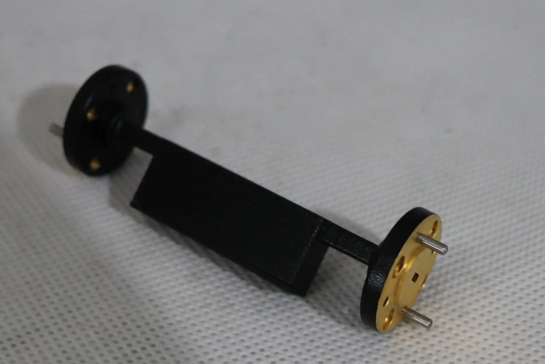
This is how waveguide fixed attenuators work: The resistive part inside a waveguide fixed attenuator, which is usually a lossy dielectric vane or wedge that is angled parallel to the electric field, takes in RF energy and turns it into heat. The process that causes attenuation is this change. It's also where the temperature force comes from, which is what causes drift. The waveguide body (often made of Oxygen-Free Copper, Aluminum 6061, or Brass) grows at a different rate than the resistor insert. This causes tiny mechanical shifts that change how the component works electrically.
Root Causes of Drift in Fixed Attenuators Under High Power
Thermal Mechanisms
The absorbent part gets hot when continuous-wave (CW) RF power is applied. Temperature-dependent resistance means that the way materials like resistive ceramics and ferrite compounds absorb energy changes as they get hotter. High-quality waveguide fixed attenuators use absorbers that don't change much when the temperature does, like Silicon Carbide composites. This keeps the attenuation fixed within <0.005 dB/°C. Without this stabilization, as the temperature goes up, the effective attenuation value changes, and the flatness of the insertion loss across the band gets worse.
The attenuator's internal shape is also physically changed by thermal expansion. The resistive vane moves slightly in relation to the waveguide walls, which changes how the vane is connected to the electric field distribution. This isn't just a hypothetical worry; it's a known way for high-power transmitter chains to fail.
Mechanical and Environmental Factors
Thermal factors are not the only cause of drift. Over time, these extra stresses make the problem worse:
- Connector torque stress: When flange connections are too tight or too loose, they put mechanical strain on the waveguide body. This deforms the internal cavity slightly and changes the VSWR from its original value. When the VSWR goes from 1.10:1 to 1.25:1, a lot more power is sent back to the source.
- Vibration fatigue: In airborne radar or mobile defense platforms, mechanical vibration slowly loosens joints. This lowers the integrity of the contact at the waveguide interface and causes return loss instability.
- Humidity ingress: When moisture gets into the waveguide cavity, especially in outdoor SATCOM earth station installations, it changes the dielectric properties of the medium inside, which changes the electrical properties of the part in ways that are hard to predict or undo.
These added pressures explain why a waveguide fixed attenuator that works fine on the bench might move around a lot after six months of use in the field. Understanding these processes is the first step in building and keeping a strong high-power RF chain.
Mitigating Drift: Principles and Best Practices
Material and Design Choices That Matter
The best way to stop drift is to start with the design phase. Low-thermal-expansion alloys, like Invar-based housings or silver-plated Oxygen-Free Copper, keep the shape of waveguide fixed attenuators from changing shape when the temperature changes. With built-in cooling fins or heat spreaders, the part can lose heat more quickly, bringing the temperature of the absorber closer to room temperature. The current standard for precision uses is metrology-grade waveguide fixed attenuators with a VSWR of less than 1.10:1 and an attenuation flatness of within ±0.2 dB across the band.
Installation and Maintenance Protocols
Aside from the construction of the parts, proper treatment greatly increases the duration of stable operation. Here are the ways of installing and taking care of things that really make a difference:
- Apply the manufacturer's specified flange torque — Using a calibrated torque wrench, apply the flange torque that the manufacturer specifies. For standard WR-series flanges, this is usually 8 to 12 inch-pounds. When you under-torque, gaps cause reflection, and when you over-torque, the flange contact surface gets deformed.
- Inspect O-ring seals and gaskets — Check the O-ring seals and gaskets every time you do maintenance to keep humidity out, especially if you are using the machine outside or in a high-humidity area.
- Verify VSWR periodically — As part of regular routine maintenance, check VSWR with a Vector Network Analyzer (VNA) on a regular basis. This is especially important after any physical system interruption.
When these practices are combined with a thorough review of all datasheets before purchasing, incidents related to drift are greatly reduced. Always make sure that the waveguide fixed attenuator's rated average power and peak power specs include a safety range above the levels at which your system actually works.
Choosing the Right Attenuator for High-Power Applications
Matching Specifications to System Requirements
It's not as simple as matching the dB number and waveguide size when choosing a waveguide fixed attenuator. The working frequency band must match the waveguide size. For example, WR-90 is needed for X-Band (8.2–12.4 GHz), while WR-28 is needed for Ka-Band (26.5–40 GHz). When you use the wrong size, you can create cutoff conditions or higher-order mode propagation, both of which make the device behave in unpredictable ways when power is applied.
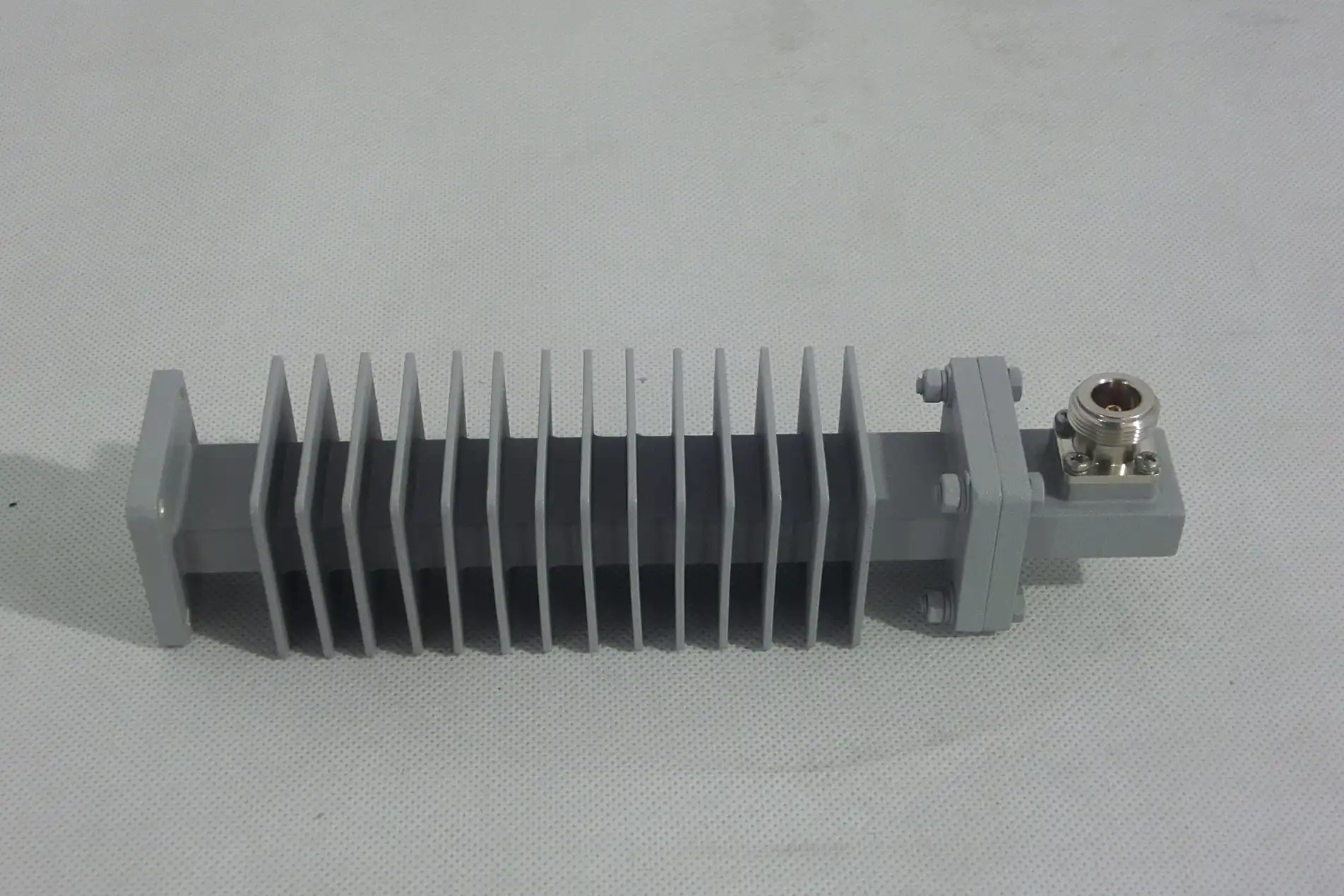
Waveguide fixed attenuators that are built with tighter dimensional limits work better for systems that operate above 18 GHz, like Ku-Band satellite uplinks or W-Band test tools. This is because at millimeter-wave frequencies, even small geometric differences can cause insertion loss variance that can be measured. Peak power handling is limited not only by heat capacity, but also by voltage breakdown (arcing) inside the waveguide tunnel. This is a factor that needs to be checked against the pulse power levels of your system.
When it comes to long-term stability for high-power passive applications, waveguide fixed attenuators always do better than variable and electronic types. This is because they don't have any active parts or tuning mechanisms that can break down or drift on their own.
Procurement Considerations for High-Power Waveguide Fixed Attenuators
When engineers buy high-power passive components, the choices they make have bigger effects than they think at first. Custom waveguide fixed attenuators, which are made to non-standard attenuation values, specialized flange configurations, or extended power ratings, can have lead times of four to twelve weeks. To keep your program on schedule, you need to start working with your supplier as soon as possible.
Minimum order numbers (MOQs) are very different from one maker to the next. When you buy in bulk through established dealer networks, the cost per unit goes down, and manufacturing tolerances are kept the same from lot to lot. This is important when testing a fleet of similar test instruments. The initial cost should be compared to the total cost of ownership, taking into account the risk of field drift, the time needed for recalibration, and the need for replacement cycles.
Having a lot of paperwork, like calibration certificates, thermal derating curves, and material compliance records (MIL-DTL-3933 if needed), lowers the risk of integration and helps defense and aerospace programs follow the rules. After-sales support that is quick and helpful is not a luxury; it's a way to lower your risks.
Conclusion
Drift in a waveguide fixed attenuator at high power is a predicted result of thermal energy conversion, the science of the material, and mechanical stress. It is not a failure that happens by chance. You can keep the integrity of the system throughout its entire operating span by figuring out what's causing problems, choosing materials that won't melt, installing them correctly, and making sure that the parts you use meet your exact frequency and power needs. By involving suppliers early on, demanding full documentation, and setting up preventive maintenance schedules, proactive procurement can turn a possible weakness into a managed, reliable system element.
FAQ
How does temperature affect attenuation accuracy?
Its resistance changes as the internal filter changes RF energy into heat. High-quality waveguide fixed attenuators use Silicon Carbide composites or specialty ferrite ceramics, which are thermally stable, along with cooling fins to keep the attenuation fixed at less than <0.005 dB/°C.
What distinguishes a standard attenuator from a metrology-grade model?
Metrology-grade units have a VSWR of less than 1.10:1 and an attenuation flatness of less than 0.2 dB across the rated band. Standard models can handle VSWR up to 1.25:1, which is fine for many system-level tasks but not enough for calibration-level work.
Can a fixed waveguide attenuator operate bidirectionally?
Most waveguide fixed attenuators work in both directions and are electrically symmetric. But when there is a lot of power, the shape of the heat sink might prefer a certain input port for the best heat absorption. Always check this with the datasheet from the manufacturer.
What limits peak power handling?
Peak power capacity is limited not only by temperature limits but also by voltage breakdown (arcing) inside the waveguide hollow. The internal shape needs to keep the field intensities from getting too high and breaking the dielectric of the medium inside.
Partner with ADM for Reliable Waveguide Fixed Attenuator Solutions
ADM makes precise waveguide fixed attenuators for high-power settings that are hard to work in, like SATCOM earth stations, defense radar systems, and millimeter-wave research and development labs. ADM is a reliable company that makes waveguide fixed attenuators. They have strict thermal management, tight dimensional tolerances, and full documentation support. You can email our tech team at craig@admicrowave.com to talk about your exact needs and get a price right away.
References
1. Pozar, D. M. — Microwave Engineering, 4th Edition. Wiley, 2011.
2. IEEE Transactions on Microwave Theory and Techniques — "Thermal Effects on Passive Microwave Component Performance." IEEE, 2018.
3. MIL-DTL-3933 — Detail Specification: Attenuators, Fixed and Variable, Radio Frequency. U.S. Department of Defense, 2015.
4. Montgomery, C. G., Dicke, R. H., & Purcell, E. M. — Principles of Microwave Circuits. MIT Radiation Laboratory Series, McGraw-Hill, 1948.
5. Microwave Journal — "Power Handling and Thermal Management in Waveguide Passive Components." Microwave Journal, 2020.
6. Collin, R. E. — Foundations for Microwave Engineering, 2nd Edition. IEEE Press / Wiley-Interscience, 2001.
YOU MAY LIKE
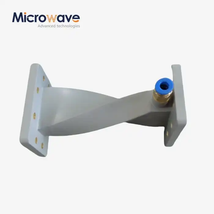 VIEW MOREInflatable twist waveguide
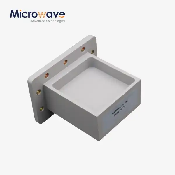 VIEW MORECustom WG to Coaxial Adapter
 VIEW MOREWG Twist
 VIEW MORERight Angle Waveguide To Coaxial Adapter
 VIEW MOREWG Dual-Channel Rotary Joint
 VIEW MOREDual Channel Coaxial Rotary Joint
 VIEW MOREHigh Power Coaxial Switch
 VIEW MOREConical Linear Polarization Horn Antenna
