O-Ring vs D-Ring Waveguide Flange Gasket: Which Seal Do You Need?
When it comes to maintaining signal integrity in RF and microwave systems, the waveguide flange gasket you choose matters more than most engineers initially expect. O-Ring and D-Ring gaskets both serve the fundamental purpose of sealing waveguide flange interfaces—preventing RF leakage, moisture ingress, and pressure loss. However, their cross-sectional geometry, compression behavior, and application suitability differ significantly. Choosing incorrectly can degrade VSWR performance, accelerate wear, or compromise environmental sealing in mission-critical systems. This guide walks you through the key distinctions so you can make a confident procurement decision.
Understanding Waveguide Flange Gaskets: Basics and Applications
At the mechanical and electrical point where two waveguide flanges meet, there is a waveguide flange gasket. It needs to do two things: keep the electrical connection across the joint to stop RF leaks, and keep out moisture, dust, and other things that could damage the internal waveguide.
Material Composition and Its Impact
Silicone elastomers, fluorosilicone (for use with fuel or solvents), and PTFE mixtures are all common materials for gaskets. Conductive types use nickel-graphite (Ni/C) or silver-plated aluminum (Ag/Al) particles as fillers to get a volume resistance below 0.005 ohm-cm. When you choose the right material, it affects how it reacts to temperature changes (silicone usually works between -55°C and +125°C), chemicals, and how it holds its shape over a long period of time.
Where These Seals Are Deployed
There are a lot of tough places where flange seals are needed. In radar systems for spacecraft, they have to be able to handle dynamic vibration and fast temperature changes without losing their electrical connection. At SATCOM ground stations, they seal waveguide runs that are under a lot of pressure and work with high-power amplifier loads. Any dielectric breakdown from moisture can lead to catastrophic arcing. Galvanic compatibility between the gasket filler and the aluminum flange is what determines how long naval communication arrays will last when they are exposed to salt spray. What all of these places have in common is that a broken seal directly leads to poor signal transfer or system downtime.
O-Ring vs D-Ring Waveguide Flange Gasket: Design and Performance Comparison
Getting to know the shape of each type of seal is the easiest way to choose the right waveguide flange gasket.
O-Ring Gasket: Circular Cross-Section Versatility
An O-Ring gasket has a circular cross-section that changes shape evenly when the flange is compressed. This shape spreads the clamping force equally around the edge, and it can work with some small surface irregularities on the flange face. O-rings work efficiently at a wide range of working pressures and fit well with standard groove-style flanges. Their constant circular compression also provides stable contact resistance, which helps shielding work well across frequencies from 1 GHz to millimeter waves.
D-Ring Gasket: Flat-Base Stability for Critical Geometries
A D-Ring gasket has a cross-section that looks like a D. It has a flat bottom and a rounded closing cap. During torque-down, the flat base stays tightly against the flange face and doesn't move or roll to the side. When an O-Ring might move out of place in choke-flange setups or shallow groove profiles, this shape works great. The D-Ring also doesn't bend when put together and taken apart in a certain order, which is important for systems that need to be taken apart and put back together again and again for upkeep.
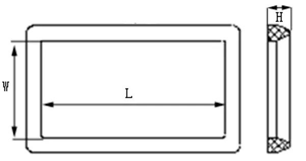
Here is a direct comparison of the two seal types across procurement-relevant parameters:
- Compression behavior: O-rings can be compressed both radially and axially, which makes them useful for distributing loads in different ways. D-Rings mostly compress along the rounded crown, which makes deflection control more predictable in flanges with tight tolerances.
- Positional stability: D-Rings don't move laterally during bolt torque sequences, but O-Rings may need groove retention to stay in place on smooth flange surfaces.
- Temperature and pressure cycling: Both silicone-based types can handle the normal temperature range of −55°C to +125°C, but in aircraft use, fluorosilicone D-Rings keep their shape better after repeated thermal shock.
- Reusability: After flange separation, neither type should be used again. After the original twist, conductive elastomers take on a permanent compression set, and reuse adds unknown EMI shielding gaps and possible pressure leaks.
When made to the right specifications, both types of seals meet MIL-DTL-83528 requirements, and die-cut tolerances of ±0.005 inches make sure they line up with standard waveguide apertures like WR-90, WR-137, and more.
How to Choose the Right Waveguide Flange Gasket for Your Application
Before you can choose the right waveguide flange gasket, you need to have a clear picture of the working environment. This includes not only the frequency range but also the full mechanical and chemical conditions that the seal will be in.
Key Selection Criteria
Start with these three basic questions: What is the shape of the flange interface? Is it choked, grooved, or flat-contact? What kinds of environmental exposures apply? Is it nitrogen under pressure, being close to jet fuel, or salt fog? How often do you get to the repair area? O-Rings can usually be attached to grooved flanges without any extra support. Choke flanges and short shapes work best with D-Rings because they stay in place. Any cross-section type of fluorosilicone matrix material needs to be used in places where hydrocarbons are present. D-Rings are better at resisting compression creep over long dwell periods, which is helpful for systems that don't need to be serviced very often.
Galvanic interaction between the material and the joint is also very important. When aluminum flanges are exposed to moisture, silver-aluminum (Ag/Al) fillers are the best conductive compound because they get rid of the electrochemical potential difference that speeds up corrosion at the gasket-flange interface.
Installation and Maintenance Best Practices for Waveguide Flange Gaskets
Even the best-specified waveguide flange gasket doesn't work well if the fitting steps aren't followed exactly.
Critical Installation Steps
The surfaces of the flanges that fit together must be smooth, clean, and free of any burrs or leftover elastomer from previous gaskets. Any kind of contamination, even finger oils, can cause dielectric problems at the joint. Place the gasket in the middle of the waveguide so that it doesn't stick out into the opening. Any protrusion acts as an iris, reflecting signals and causing impedance mismatch that can be measured. As directed by the manufacturer, apply bolt torque in a cross-pattern sequence to get uniform compression deflection of 10 to 15% of the gasket's uncompressed thickness. When the torque is too high, conductive particles are pushed into the waveguide path, and when it is too low, the EMI seal is not complete.
Surface cracks, lasting flattening beyond accepted compression set limits, and discoloration that shows heat decay should all be checked for on a regular basis. It is best practice in the business to replace the seal every time the flange opens.
Procurement Insights: Ordering, Supply, and Lead Time
When B2B buying teams decide where to buy things, they look at more than just the unit price. The total cost of acquisition is affected by lead time, documentation, and the dependability of the supplier. Working directly with an experienced waveguide flange gasket maker lets you match specifications for waveguides that aren't the standard size, choose your own conductive filler, and get material certifications that can be tracked back to MIL-DTL-83528 or ISO 9001 quality control systems. Arrangements for bulk orders usually lead to lower prices and fewer points of contact in the supply chain. It's common to ask for samples before committing to large orders so that you can make sure that the dimensions fit and that the product will not shrink when it's used with your unique flange hardware. For projects with set release dates, global logistics help and clear information about lead times become even more important.
Conclusion
There is a scientific reason behind the choice between an O-Ring and a D-Ring waveguide flange gasket. This reason is based on the shape of the flange, how it will be used, and how it should be maintained. D-Rings offer better positional stability and bending control in shallow or choke-style interfaces, while O-Rings offer flexible compression across a wide range of groove designs. The right gasket selection leads to long-lasting RF system performance by matching the material's makeup to the temperature and chemical conditions, making sure it is galvanically compatible with the flange metal, and following exact fitting torque protocols.
FAQ
Can O-ring gaskets be used for high-frequency waveguide applications above 40 GHz?
O-Ring covers can work at millimeter-wave frequencies as long as the material doesn't go into the waveguide opening and the dimensions are kept to ±0.005 inches. Any extension, no matter how small, causes big resistance changes at higher frequencies. Precision die-cut conductive O-Rings with a volume resistivity of less than 0.005 ohm-cm are good for situations where the groove geometry guarantees good retention.
What material performs best in extreme temperature environments?
Fluorosilicone-based gaskets keep their elastomeric integrity from -55°C to +125°C and can't be exposed to hydrocarbons. For uses that go through quick changes in temperature, like aircraft radar, fluorosilicone works better than regular silicone at keeping its shape and not deforming when it gets cold.
How often should flange gaskets be inspected and replaced?
It is suggested that you do an inspection at every planned repair interval. Every time a flange opens, the waveguide flange gasket has to be replaced, even if it looks fine. This is because the compression set makes used gaskets unreliable for both EMI shielding and pressure sealing. In places with a lot of vibration or temperature changes, inspections should be done more often.
Partner with ADM for Precision Waveguide Flange Gasket Solutions
Every waveguide assembly part that ADM sells comes with over 20 years of production experience. As a reliable waveguide flange gasket provider, we provide ISO 9001-certified and RoHS-compliant sealing solutions that can be fully customized. These include OEM-ready paperwork, quick prototype turnaround, and support for global logistics. You can email our engineering team at craig@admicrowave.com to get a sample or price that is made just for your purpose.
References
1. IEEE Transactions on Microwave Theory and Techniques — 2019
2. MIL-DTL-83528, General Specification for Gaskets, Sealing, Electrically Conductive — 2015
3. Journal of Electromagnetic Waves and Applications — 2021
4. IEC 60068-2: Environmental Testing for Electronic Equipment — 2020
5. ASTM D991, Standard Test Method for Volume Resistivity of Conductive Plastics — 2018
6. IEEE Standard 299, Standard Method for Measuring the Effectiveness of Electromagnetic Shielding Enclosures — 2006