


What Are the Main Components of a Double Ridge Waveguide Tube?
When designing high-frequency microwave systems for satellite communications, radar installations, or 5G networks, engineers face a critical challenge: achieving wide bandwidth transmission without sacrificing signal integrity. The Double Ridge Waveguide Tube addresses this challenge through its specialized internal structure, which consists of precisely engineered ridges, metal housing, flanges, and surface treatments. Understanding these main components is essential for optimizing system performance and ensuring reliable electromagnetic wave propagation across frequencies ranging from 1 GHz to 110 GHz in demanding aerospace, defense, and telecommunications applications.
Understanding the Core Structure of Double Ridge Waveguide Tubes
The fundamental architecture of a Double Ridge Waveguide Tube distinguishes it from conventional rectangular waveguides through its distinctive internal geometry. At its heart, the Double Ridge Waveguide Tube features two parallel ridges that protrude inward from opposite walls of the waveguide housing, creating a specialized electromagnetic environment that fundamentally alters how radio frequency energy propagates through the structure. These ridges extend longitudinally along the entire length of the waveguide, positioned parallel to the narrow walls of the rectangular cross-section. The precise dimensions, spacing, and profile of these ridges are meticulously calculated based on the target frequency range, required bandwidth, and impedance characteristics of the specific application. The waveguide housing itself forms the outer conductive boundary that contains and guides the electromagnetic waves. Manufactured from high-quality metals such as aluminum, copper, or brass, the housing provides both mechanical rigidity and excellent electrical conductivity essential for minimizing signal loss. Advanced Microwave Technologies Co., Ltd utilizes precision CNC machining techniques to achieve the tight dimensional tolerances required for optimal performance, with tolerances measured in microns becoming increasingly critical at higher frequencies. The housing dimensions directly correlate with the operational frequency range, with larger cross-sections accommodating lower frequencies and smaller dimensions suited for millimeter-wave applications. Standard models like WRD180, WRD350, WRD500, and WRD750 are designed to cover specific frequency bands while maintaining the inherent bandwidth advantages of the double ridge configuration.
The Ridge Configuration and Electromagnetic Field Distribution
The double ridge geometry creates a carefully controlled electromagnetic environment that dramatically improves performance characteristics compared to conventional rectangular waveguides. These ridges effectively narrow the gap in specific regions of the waveguide cross-section, which fundamentally alters the electric field distribution in ways that extend operational bandwidth and improve impedance matching capabilities. While conventional rectangular waveguides typically operate effectively within a frequency range ratio of approximately 1.5:1, Double Ridge Waveguide Tubes can support bandwidth ratios of 3:1 or greater, enabling operation across substantially wider frequency ranges without requiring multiple waveguide components. The engineering behind these ridges involves complex electromagnetic calculations to determine optimal ridge height, width, and profile shape. The ridge dimensions are proportionally sized to the overall waveguide cross-section, with typical ridge heights ranging from 30 to 50 percent of the broad wall spacing. This configuration lowers the cutoff frequency by effectively reducing the waveguide's electrical width while simultaneously extending the frequency range before higher-order modes become problematic. For telecommunications infrastructure, research facilities, and military systems, this translates to greater flexibility and reduced component count, as a single Double Ridge Waveguide Tube can replace multiple conventional waveguides in many scenarios.
Material Selection and Surface Treatment Components
Material composition plays a pivotal role in determining the performance, durability, and operational characteristics of Double Ridge Waveguide Tubes. Aluminum represents the most commonly selected material due to its excellent balance of lightweight properties, good electrical conductivity, and cost-effectiveness for a broad range of applications. Aluminum waveguides are particularly well-suited for applications where weight reduction is critical, such as aerospace systems, satellite ground stations, and portable radar installations. The material's natural oxide layer provides inherent corrosion resistance, making aluminum Double Ridge Waveguide Tubes reliable choices for outdoor installations and challenging environmental conditions. Copper variants offer superior electrical conductivity that minimizes transmission losses, making them the preferred choice for applications where signal integrity is paramount and weight considerations are secondary. The lower resistivity of copper compared to aluminum results in reduced insertion loss, particularly beneficial in high-power transmission systems and precision measurement applications where every fraction of a decibel matters. Brass options provide enhanced durability and machinability, offering an excellent middle ground for general-purpose applications while maintaining strong performance characteristics. The selection between these materials depends on specific system requirements, with engineers weighing factors including operating frequency, power handling needs, environmental conditions, size constraints, and budget considerations.

Advanced Surface Treatment Technologies
Beyond base material selection, Advanced Microwave's Double Ridge Waveguide Tubes undergo specialized surface treatments to further enhance performance and longevity. Silver plating represents one of the most effective treatments for improving conductivity, significantly reducing insertion loss and improving overall system efficiency. The silver layer, typically applied through electroplating processes to thicknesses of several microns, provides the lowest surface resistance among practical plating options, which directly translates to reduced signal attenuation. This treatment is particularly valuable for high-frequency applications where skin depth effects concentrate current flow in the surface layers of the conductor. Gold plating options provide not only excellent conductivity but also superior corrosion resistance, making these components suitable for deployment in harsh environmental conditions where exposure to moisture, salt spray, or corrosive elements is a concern. While gold exhibits slightly higher resistivity than silver, its chemical stability ensures that performance characteristics remain consistent over extended operational lifetimes without degradation from oxidation or tarnishing. Passivation treatments for stainless steel variants create a protective oxide layer that enhances corrosion resistance without significantly impacting electrical performance. The surface treatment selection directly impacts the component's VSWR characteristics, with properly treated Double Ridge Waveguide Tubes achieving VSWR values of 1.15:1 or better across their operational bandwidth.
Flange Assemblies and Connection Interfaces
Flanges constitute critical structural and electrical components of Double Ridge Waveguide Tube assemblies, providing standardized interfaces for connecting multiple waveguide sections and integrating with other microwave components. These precision-machined mechanical interfaces ensure proper alignment between connected components while maintaining excellent electrical continuity and minimizing reflections at junction points. Advanced Microwave Technologies Co., Ltd manufactures flanges using the same high-quality materials as the waveguide body, typically aluminum or copper depending on the application requirements, to ensure thermal expansion compatibility and prevent galvanic corrosion issues. The flange design incorporates multiple critical features including bolt hole patterns conforming to industry standards, precisely machined mating surfaces with tight flatness tolerances, and gasket grooves where environmental sealing is required. Standard flange types include UG-style square flanges, cover flanges, and specialized military-specification configurations depending on the application and customer requirements. The mating surfaces require exceptional flatness and finish quality, typically specified to within a few micrometers, to ensure proper RF performance and prevent power loss at the interface. Bolt hole positions are precisely located to ensure consistent and repeatable connections while maintaining mechanical stability under operational vibration and thermal cycling conditions.
Precision Alignment and Mounting Features
Proper alignment between connected Double Ridge Waveguide Tube sections is essential for maintaining signal integrity and preventing mode conversion or excessive reflection losses. The flange assemblies incorporate dowel pin holes or other precision alignment features that ensure correct rotational orientation and eliminate potential misalignment during installation. These alignment pins register against precisely machined holes in the mating flange, guaranteeing that the internal ridges of connected waveguide sections maintain perfect continuity. Even minor misalignments of a fraction of a millimeter can introduce significant performance degradation, particularly at higher operating frequencies where wavelengths become comparable to typical mechanical tolerances. The mounting bolt patterns are designed to provide uniform clamping force around the entire perimeter of the flange interface, preventing localized stress concentrations that could lead to waveguide deformation or inconsistent electrical contact. Torque specifications for flange bolts are carefully determined based on material properties, flange dimensions, and the required contact pressure to achieve optimal RF performance. In high-power applications, proper flange connections also serve thermal management functions, providing heat conduction paths that help dissipate power losses generated within the waveguide structure. Advanced Microwave offers customization options for flange configurations, allowing integration with customer-specific mechanical interfaces and mounting requirements while maintaining the electrical performance specifications of the Double Ridge Waveguide Tube.
Internal Load Elements and Termination Components
For complete waveguide systems, internal load elements represent specialized components designed to absorb microwave energy at specific points within the transmission line. These critical elements convert RF energy to heat while maintaining minimal reflection back toward the source, a characteristic quantified by the component's return loss or VSWR specification. The load element itself is engineered using carefully selected materials with specific dielectric and loss properties that efficiently convert electromagnetic energy to thermal energy across the operational frequency range. Material composition is optimized for various frequency bands across the product line, ensuring consistent performance from the lowest to highest operational frequencies. The geometry of internal load elements typically features tapered or conical profiles that gradually increase the resistive loading as energy propagates deeper into the termination. This graduated approach minimizes impedance discontinuities that would otherwise cause reflections, allowing the Double Ridge Waveguide Tube to maintain excellent VSWR characteristics even when terminated. The physical length of the load element is directly related to the lowest operating frequency, with longer tapers required for lower frequency applications to achieve smooth impedance transitions. Advanced Microwave's engineering team carefully balances load element length against overall component size constraints while maintaining the specified electrical performance across the full operational bandwidth.
Power Handling and Thermal Management
Power handling capability represents a critical specification for Double Ridge Waveguide Tube components, particularly in high-power radar systems, satellite communication ground stations, and broadcasting applications. The power rating depends on multiple factors including the operating frequency, duty cycle, ambient temperature, and cooling provisions. Advanced Microwave's Double Ridge Waveguide Tubes are engineered to handle significant power levels through careful attention to thermal management design. The component's ability to dissipate heat generated from conductor losses and any internal absorptive elements directly determines its maximum continuous and peak power ratings. Material selection significantly impacts power handling capability, with copper offering superior thermal conductivity compared to aluminum or brass, allowing more efficient heat dissipation from the waveguide structure. Surface finish quality also affects power handling, as rough surfaces can create localized hot spots that lead to arcing or thermal damage at power levels below the theoretical limit. For demanding high-power applications, Advanced Microwave can implement enhanced cooling features including heat sink structures, forced air cooling provisions, or liquid cooling interfaces that extend power handling capabilities well beyond what passive cooling can achieve. The operating temperature range of negative 55 degrees Celsius to positive 85 degrees Celsius ensures reliable operation across extreme environmental conditions encountered in aerospace, defense, and outdoor telecommunications installations.
Conclusion
Understanding the main components of a Double Ridge Waveguide Tube enables engineers to specify optimal solutions for demanding microwave applications. The integration of precision ridges, quality materials, advanced surface treatments, and robust flange assemblies ensures reliable wide-bandwidth performance across frequencies from 1 GHz to 110 GHz for critical telecommunications, aerospace, and defense systems.
Cooperate with Advanced Microwave Technologies Co., Ltd.
Advanced Microwave Technologies Co., Ltd stands as your trusted China Double Ridge Waveguide Tube factory, manufacturer, and supplier with over 20 years of specialized expertise in precision microwave components. Our comprehensive OEM services deliver customized Double Ridge Waveguide Tube solutions tailored to your exact specifications, backed by ISO 9001:2015, ISO 14001:2015, and ISO 45001:2018 certifications. Whether you need High Quality Double Ridge Waveguide Tube for sale at competitive Double Ridge Waveguide Tube prices or China Double Ridge Waveguide Tube wholesale solutions, our advanced 24m Microwave Darkroom testing facility ensures every component meets the highest performance standards. Contact our technical team today at craig@admicrowave.com to discuss your project requirements and discover how our fast prototyping, strict quality control, and superior after-sales support can optimize your microwave system performance.
References
1. Marcuvitz, Nathan. "Waveguide Handbook." McGraw-Hill Book Company, 1951.
2. Saad, Theodore S. "Microwave Engineers' Handbook: Volume 1." Artech House Publishers, 1971.
3. Collin, Robert E. "Field Theory of Guided Waves." IEEE Press Series on Electromagnetic Wave Theory, 1991.
4. Montgomery, Carol G., Robert H. Dicke, and Edward M. Purcell. "Principles of Microwave Circuits." MIT Radiation Laboratory Series, Dover Publications, 1948.
5. Ramo, Simon, John R. Whinnery, and Theodore Van Duzer. "Fields and Waves in Communication Electronics." John Wiley & Sons, 1994.
YOU MAY LIKE
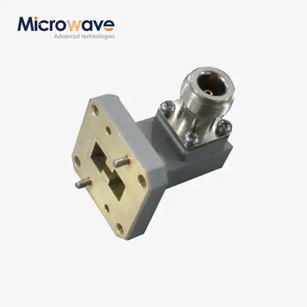 VIEW MORERight Angle Double Ridged WG To Coaxial Adapter
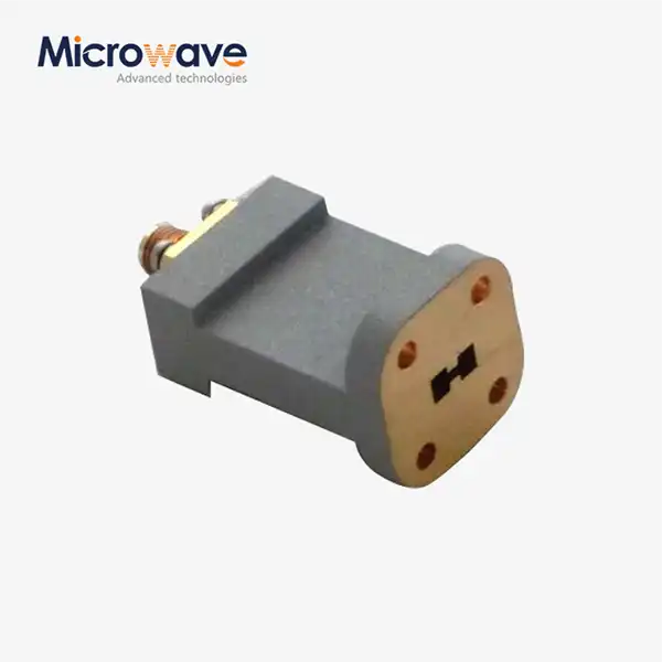 VIEW MOREEnd Launch Double Ridged WG To Coaxial Adapter
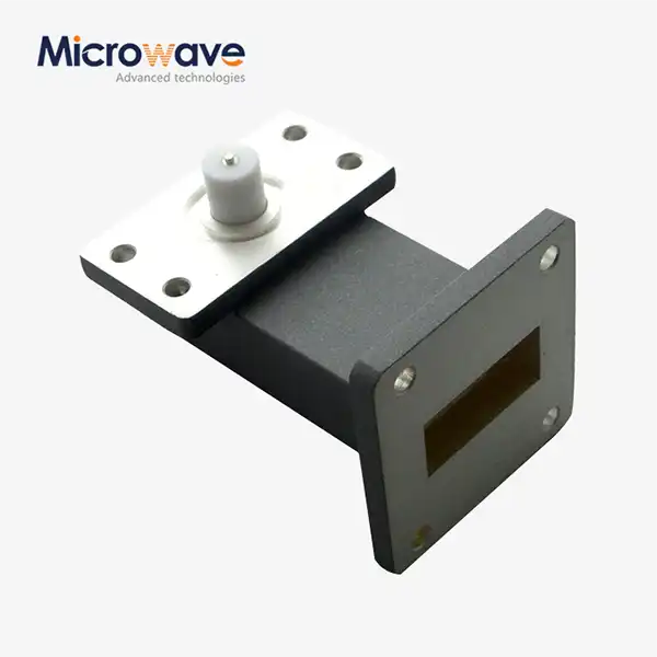 VIEW MORERight Angle Waveguide to Microstrip Adapter
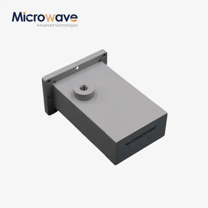 VIEW MOREWG Termination
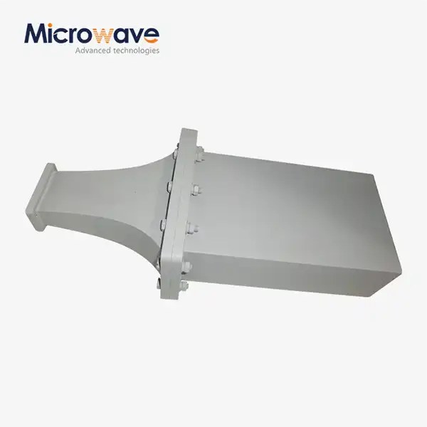 VIEW MOREDouble Ridge Waveguide Termination
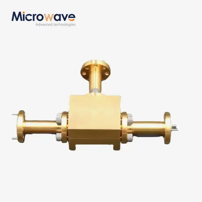 VIEW MOREWaveguide Power Divider
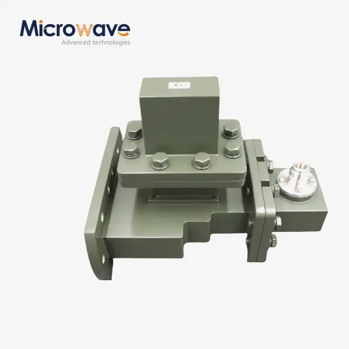 VIEW MOREE-Plane Tee
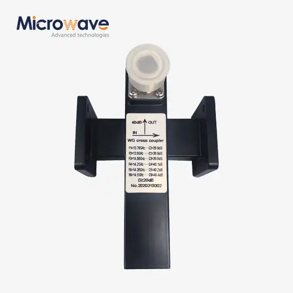 VIEW MORECrossguide Directional Coupler
