


Top Double‑Ridged Waveguide Loop Coupler Features You Must Know
When high-power RF systems fail due to inadequate power monitoring or signal degradation across wide frequency ranges, engineers face costly downtime and system failures. The Double-Ridged Waveguide Loop Coupler addresses these critical challenges by providing reliable power sensing, exceptional bandwidth coverage, and stable performance in demanding microwave applications. Understanding the essential features of this component is crucial for anyone working in satellite communications, radar systems, aerospace, or telecommunications where signal integrity and system reliability are non-negotiable.
Understanding Double-Ridged Waveguide Loop Coupler Architecture
The fundamental design of the Double-Ridged Waveguide Loop Coupler represents a sophisticated evolution in microwave component engineering. At its core, this component consists of a double-ridged waveguide section integrated with a precisely engineered coupling structure. The double-ridged waveguide itself features two opposing ridge structures positioned within the waveguide cavity, a configuration that fundamentally alters the electromagnetic field distribution compared to traditional rectangular waveguides. These ridges modify the propagation characteristics of electromagnetic waves, enabling the coupler to operate across significantly broader frequency ranges than conventional single-ridge or standard rectangular waveguide designs. The coupling mechanism typically employs a loop-shaped structure or incorporates loop elements strategically positioned within the waveguide cavity. This loop structure interacts with the electromagnetic fields propagating through the double-ridged waveguide, extracting a controlled portion of the signal for monitoring or measurement purposes. The geometric parameters of this coupling loop, including its diameter, positioning, orientation, and material composition, critically influence the coupler's overall performance characteristics. The interaction between the double-ridged waveguide architecture and the coupling loop creates a system where multiple ports can be integrated, typically including primary input and output ports along with dedicated coupling ports for signal sampling.
The electromagnetic field distribution within a Double-Ridged Waveguide Loop Coupler differs substantially from standard waveguide configurations. The ridge structures concentrate the electric field in the region between the ridges, creating a quasi-TEM propagation mode that enables lower cutoff frequencies and broader operational bandwidths. This field concentration also affects how the coupling loop extracts signal samples, with the loop positioned to optimize coupling efficiency while minimizing disruption to the main signal path. The relationship between ridge height, ridge separation distance, and coupling loop geometry must be precisely calibrated to achieve the desired coupling coefficient, directivity, and frequency response characteristics. Manufacturing tolerances become increasingly critical at higher frequencies, where even minor dimensional variations can significantly impact performance metrics such as voltage standing wave ratio, insertion loss, and coupling flatness across the operational bandwidth.
Exceptional Bandwidth Coverage of Double-Ridged Waveguide Loop Couplers
One of the most compelling features of the Double-Ridged Waveguide Loop Coupler is its remarkable frequency range capability, often spanning octave or multi-octave bandwidths. Traditional rectangular waveguide components typically operate over relatively narrow frequency ranges, constrained by the waveguide's cutoff characteristics and dispersion properties. The double-ridged architecture overcomes these limitations through its modified field distribution and reduced cutoff frequency, enabling operation from as low as 0.5 GHz up to 110 GHz in advanced implementations. This extensive frequency coverage proves invaluable for applications requiring broadband performance, such as modern 5G telecommunications infrastructure, emerging 6G technology development, and multi-band radar systems that must simultaneously process signals across different frequency allocations. The ability to maintain consistent performance across wide frequency ranges eliminates the need for multiple narrowband components, simplifying system design and reducing overall hardware complexity. In satellite ground stations, for instance, a single Double-Ridged Waveguide Loop Coupler can handle both legacy communication frequencies and newer high-throughput satellite bands, providing continuous power monitoring across the entire operational spectrum. Similarly, in defense applications, military surveillance radars benefit from the coupler's ability to support frequency-agile operation, where the radar system rapidly switches between different frequencies to avoid detection or jamming. The wide bandwidth capability also proves essential in spectrum monitoring applications, where regulatory agencies and telecommunications operators must simultaneously observe multiple frequency bands for interference detection, signal characterization, and compliance verification.
The frequency response characteristics of Double-Ridged Waveguide Loop Couplers exhibit remarkable flatness when properly designed and manufactured. Coupling variation typically remains within tight tolerances across the operational bandwidth, often achieving variations of less than ±1.5 dB from the nominal coupling value. This coupling flatness ensures that power measurements remain accurate regardless of the operating frequency, a critical requirement for calibrated test systems and precision measurement applications. The broadband nature of these couplers also accommodates the increasingly common practice of carrier aggregation in wireless communications, where multiple frequency channels are combined to increase data throughput. System designers can rely on a single Double-Ridged Waveguide Loop Coupler to monitor aggregated carriers spanning hundreds of megahertz or even gigahertz of bandwidth, maintaining measurement accuracy across all combined channels.

Critical Performance Specifications and Measurement Parameters
The performance envelope of a Double-Ridged Waveguide Loop Coupler is defined by several interconnected electrical parameters that collectively determine its suitability for specific applications. Coupling coefficient represents the fundamental characteristic, indicating the ratio between the power in the main transmission path and the power extracted at the coupling port. Standard coupling values typically range from 20 dB to 60 dB, with each application requiring carefully selected coupling levels to balance measurement sensitivity against minimal disruption to the main signal. High-power transmitter monitoring might employ 40 dB or 50 dB coupling to extract sufficient signal for accurate measurement while keeping the coupled power at manageable levels, whereas sensitive receiver applications might use 20 dB or 30 dB coupling to obtain stronger samples for analysis. Directivity performance distinguishes well-designed Double-Ridged Waveguide Loop Couplers from lower-quality alternatives. Directivity measures the coupler's ability to discriminate between forward and reverse power flow, essentially quantifying how well the coupling mechanism responds only to signals traveling in the intended direction while rejecting reflections or backward-traveling waves. Minimum directivity specifications typically exceed 12 dB to 15 dB across the operational bandwidth, with premium designs achieving 18 dB or higher. This directional selectivity proves crucial in applications where accurate forward power measurement must be maintained even when significant reflected power exists due to antenna mismatch, load variations, or other system imperfections. In radar systems, for example, high directivity ensures that transmitted power measurements remain accurate regardless of target return signals or environmental reflections.
Voltage Standing Wave Ratio and insertion loss specifications directly impact system efficiency and signal integrity. Well-engineered Double-Ridged Waveguide Loop Couplers maintain VSWR values of 1.15:1 or better on the main transmission path, indicating minimal impedance discontinuity and maximum power transfer efficiency. The coupling port typically exhibits slightly higher VSWR, often specified at 1.25:1 or 1.30:1, which remains acceptable given the significantly lower power levels present at this port. Insertion loss, representing the power dissipated within the coupler structure itself, must be minimized to preserve overall system efficiency. Premium Double-Ridged Waveguide Loop Couplers achieve insertion losses below 0.5 dB across their operational bandwidth, ensuring that the main signal path experiences minimal degradation. These performance specifications collectively determine the coupler's suitability for demanding applications where system efficiency, measurement accuracy, and signal integrity cannot be compromised.
Material Selection and Construction Excellence
The physical construction and material composition of Double-Ridged Waveguide Loop Couplers significantly influence their performance, durability, and suitability for different operational environments. Aluminum alloys represent the most common material choice, offering an excellent balance of electrical conductivity, mechanical workability, weight considerations, and cost-effectiveness. High-purity aluminum provides low-loss signal propagation while remaining light enough for aerospace applications where every gram matters. The material's machinability enables precise fabrication of the complex internal ridge structures and coupling loop geometries essential for achieving specified electrical performance. Surface treatments such as chromate conversion coating or specialized finishes enhance corrosion resistance, particularly critical for outdoor installations, maritime applications, or environments with high humidity or salt exposure. Brass and copper alternatives find application where enhanced electrical performance justifies their greater weight and cost. Copper's superior electrical conductivity reduces ohmic losses, making it preferable for ultra-low-loss applications or systems operating at the highest frequencies where skin effect losses become significant. Brass offers intermediate performance between aluminum and copper while providing excellent machinability for intricate internal features. The material selection process must account for thermal expansion characteristics, especially in systems experiencing wide temperature variations. Mismatched thermal expansion between different components can introduce mechanical stress, dimensional changes affecting electrical performance, or even physical damage during thermal cycling. Advanced designs incorporate materials and construction techniques that maintain dimensional stability across operational temperature ranges that may span from cryogenic conditions in space applications to elevated temperatures in high-power transmitter environments.
Manufacturing precision directly correlates with achievable performance, particularly at higher frequencies where wavelengths become comparable to mechanical tolerances. Computer Numerically Controlled machining enables fabrication of ridge profiles, coupling loop geometries, and port interfaces with tolerances measured in micrometers. Dip-brazing construction techniques create hermetically sealed assemblies that exclude moisture and contaminants while ensuring robust mechanical integrity capable of withstanding shock, vibration, and handling stresses. Surface finish quality affects both electrical performance and long-term reliability, with smoother internal surfaces reducing conductor losses and minimizing sites where corrosion might initiate. Some applications require specialized coatings such as silver plating for enhanced conductivity, gold plating for supreme corrosion resistance, or electroless nickel plating for specific environmental protection needs. The construction approach must also address pressure sealing requirements for aerospace applications or other scenarios where the Double-Ridged Waveguide Loop Coupler must maintain its electrical characteristics despite external pressure differentials or harsh atmospheric conditions.
Customization Capabilities for Specialized Applications
The versatility of Double-Ridged Waveguide Loop Coupler technology extends through comprehensive customization options that address unique application requirements across diverse industries. Frequency range customization allows engineers to optimize the coupler design for specific operational bands rather than accepting the compromises inherent in ultra-wideband designs. A narrowband Double-Ridged Waveguide Loop Coupler designed for a specific satellite downlink frequency can achieve tighter performance tolerances, improved coupling flatness, and enhanced directivity compared to a broadband design attempting to cover multiple octaves. This optimization involves adjusting ridge dimensions, spacing, and profiles to precisely control the electromagnetic field distribution at the target frequencies, while the coupling loop geometry can be tailored to achieve optimal coupling efficiency and directivity specifically within the required operational band. Dimensional customization addresses mechanical integration challenges where standard sizes prove incompatible with existing system architectures. Waveguide sizes can be adapted to match specific flange standards, whether CPR, UG, or custom flange designs proprietary to particular equipment manufacturers. Port configurations can be modified to accommodate different connector types, with SMA, Type-N, 2.92 mm, 2.4 mm, or other coaxial interfaces specified based on frequency requirements and power handling needs. Physical length constraints may necessitate compact designs where the coupler must fit within restricted spaces, requiring careful optimization to maintain electrical performance despite reduced physical dimensions. Conversely, some applications benefit from extended coupling sections that improve directivity or flatten the frequency response at the expense of larger physical size.
Environmental adaptation represents another critical customization dimension for Double-Ridged Waveguide Loop Couplers deployed in challenging conditions. Military applications may require ruggedized construction meeting MIL-STD specifications for shock, vibration, temperature extremes, and electromagnetic interference resistance. Aerospace implementations demand lightweight materials, pressure-sealed construction for altitude operation, and thermal designs accommodating the vacuum of space or atmospheric reentry conditions. Industrial environments might necessitate protection against chemical exposure, high temperatures from nearby heat sources, or physical abuse from heavy machinery operation. Each environmental consideration influences material selection, construction techniques, sealing approaches, and mounting provisions. The customization process involves close collaboration between application engineers and design teams to fully understand operational requirements, environmental stresses, performance priorities, and cost constraints, ultimately delivering a Double-Ridged Waveguide Loop Coupler precisely optimized for its intended application rather than a generic component forced to serve in a suboptimal capacity.
Conclusion
Double-Ridged Waveguide Loop Couplers deliver unmatched broadband performance, combining wide frequency coverage with precision power monitoring capabilities essential for modern microwave systems.
Cooperate with Advanced Microwave Technologies Co., Ltd.
Advanced Microwave Technologies Co., Ltd stands as a premier China Double-Ridged Waveguide Loop Coupler manufacturer, offering over 20 years of specialized expertise in precision microwave components. Our ISO-certified facilities, equipped with advanced measurement capabilities up to 110 GHz, produce High Quality Double-Ridged Waveguide Loop Couplers for satellite communications, aerospace, and defense applications worldwide. Whether you need a China Double-Ridged Waveguide Loop Coupler supplier for volume production, competitive Double-Ridged Waveguide Loop Coupler price quotes, China Double-Ridged Waveguide Loop Coupler wholesale partnerships, or custom Double-Ridged Waveguide Loop Coupler for sale with tailored specifications, our engineering team delivers rapid prototyping and technical support. Contact craig@admicrowave.com today to discuss your requirements and discover why leading global organizations trust our China Double-Ridged Waveguide Loop Coupler factory for their most demanding applications.
References
1. Pozar, D.M. "Microwave Engineering, Fourth Edition." John Wiley & Sons, 2012. Comprehensive treatment of waveguide theory, coupling mechanisms, and directional coupler design principles applicable to double-ridged configurations.
2. Helszajn, J. "Ridge Waveguides and Passive Microwave Components." The Institution of Engineering and Technology, 2020. Authoritative reference specifically addressing double-ridged waveguide technology, design methodologies, and performance characteristics.
3. Balanis, C.A. "Advanced Engineering Electromagnetics, Second Edition." John Wiley & Sons, 2012. Fundamental electromagnetic field theory underlying waveguide propagation, ridge structure effects, and coupling mechanisms.
4. Rizzi, P.A. "Microwave Engineering: Passive Circuits." Prentice Hall, 1988. Classical reference covering waveguide components, coupling structures, and measurement techniques relevant to loop coupler implementations.
5. Saad, T.S. "Microwave Engineers' Handbook, Volume 1." Artech House, 1971. Industry-standard handbook containing waveguide coupler specifications, design charts, and application guidance for loop coupler configurations.
YOU MAY LIKE
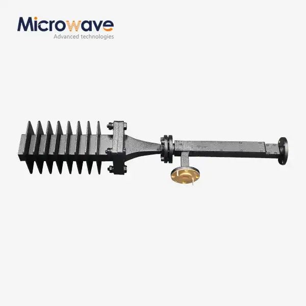 VIEW MOREWaveguide Fixed Attenuator
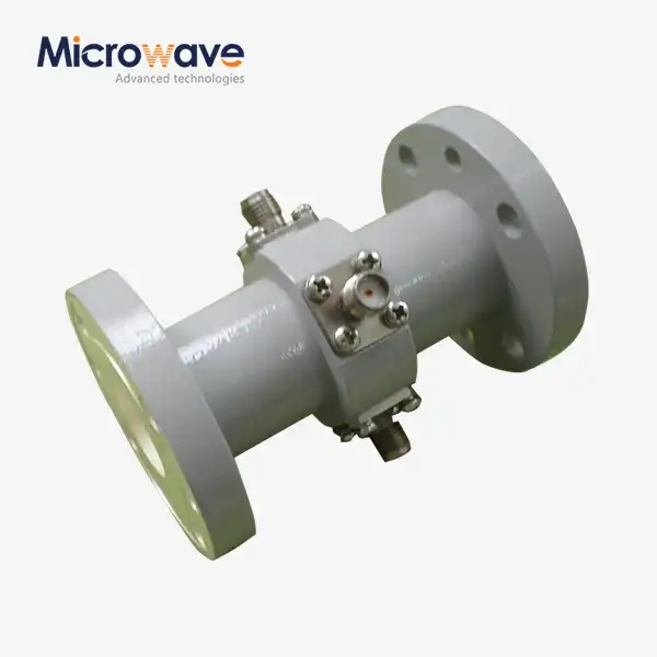 VIEW MOREWaveguide Probe Coupler
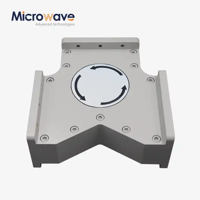 VIEW MOREHigh Power Waveguide Circulator
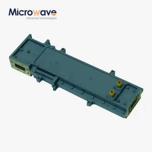 VIEW MOREHigh Power Waveguide Differential Phase Shift Circulator
 VIEW MOREWaveguide Variable Attenuator
 VIEW MOREHigh Power Waveguide Isolator
 VIEW MOREWG Bandpass Filter
 VIEW MOREWG Harmonic Filter
