Waveguide Variable Attenuator for Microwave Testing
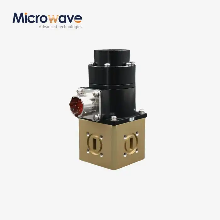
A waveguide variable attenuator is an important precision microwave part that lets you change the signal intensity in waveguide transmission systems. It usually has attenuation ranges of 0 dB to 60 dB or higher. These devices, unlike fixed attenuators, let you control the power continuously or steppedly through mechanical processes like resistive vane insertion or rotating polarization, all without getting in the way of the signal. This dynamic control feature solves important testing problems like keeping the receiver from getting too full, calibrating the radar, and making sure the power level is right in high-frequency measurement setups that work across L-Band to W-Band frequencies. This makes them essential for use in research, aerospace, and satellite communications.
Understanding Waveguide Variable Attenuators
When buying parts for mission-critical systems, purchasing workers at Advanced Microwave Technologies Co., Ltd. often have trouble telling the difference between reduction methods. Waveguide variable attenuators are different from coaxial attenuators because of how they are built and how they work.
Operating Principles and Mechanical Design
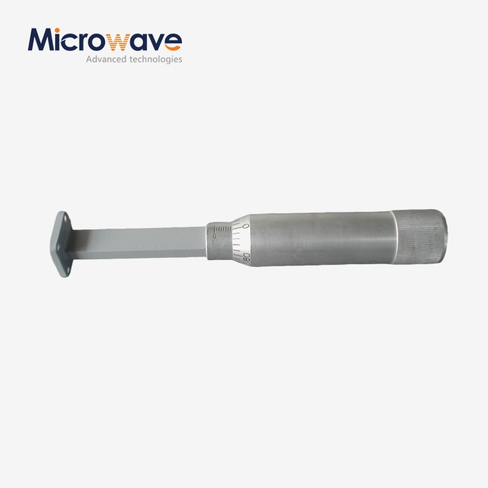
These devices control signals by interacting physically with electromagnetic fields that move through waveguide structures that are either rectangular or circular. A resistive dielectric blade that moves perpendicular to the electric field lines is the most usual way to do it. As the vane moves deeper into the waveguide channel, it takes in more and more electromagnetic energy, turning it into heat while still letting the signal pass through with a steady loss.
Rotary vane attenuators work in a different way because they use polarization rotation. Within the waveguide, a resistance element turns, which changes the angle between the polarization of the incoming signal and the direction of the material that absorbs it. This design has very good phase stability, which is an important quality for vector network analyzer readings and coherent radar systems.
Performance Specifications That Matter
Technical buyers should pay attention to a few key factors when examining these parts. For quality units, insertion loss at the zero attenuation setting usually stays below 0.5 dB, which keeps the system's performance high. The Voltage Standing Wave Ratio (VSWR) shows how well the device fits the waveguide impedance. High-end models keep the VSWR below 1.15:1 across the entire attenuation range. This keeps reflections to a minimum, which keeps upstream amplifiers from breaking or readings from being inaccurate.
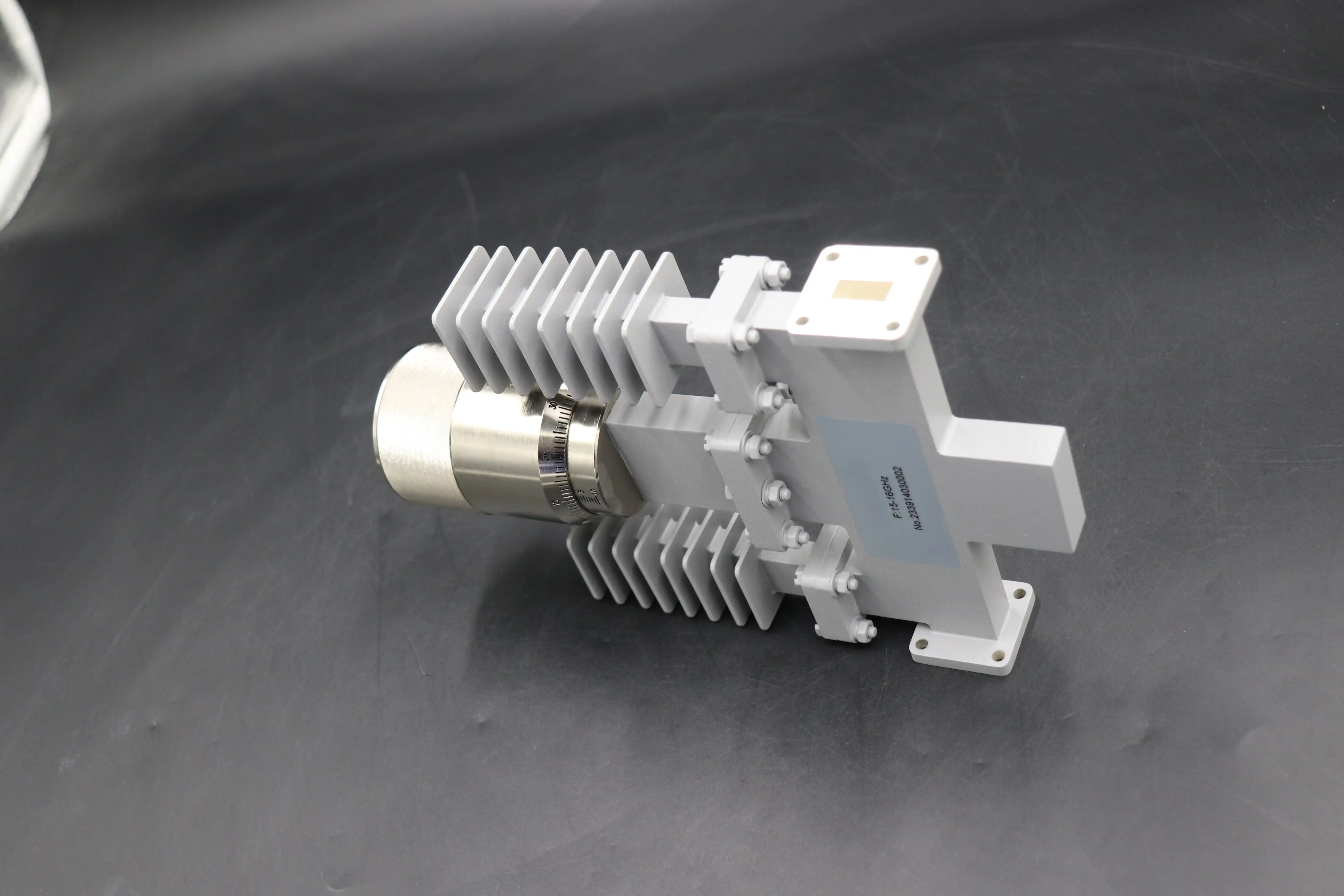
When calibrating, attenuation precision is very important. Tolerances of high-precision rotating designs are as low as ±0.1 dB, or 2% of the reading. This makes test conditions predictable. Application suitability is based on frequency bandwidth. A WR-90 waveguide attenuator designed for X-band (8.2-12.4 GHz) meets all requirements across this range. Trying to operate outside of these limits will lower performance.
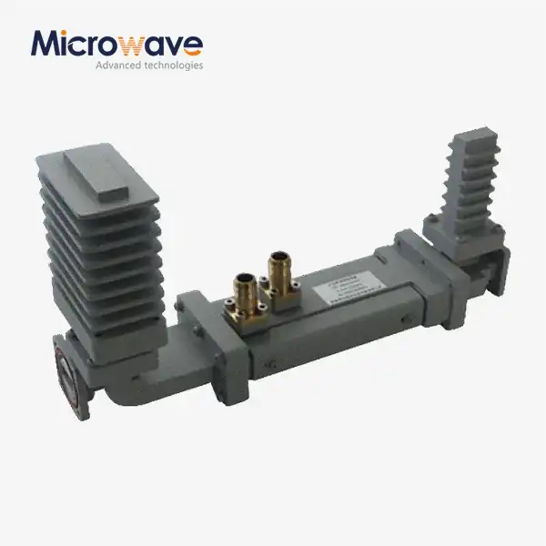
Waveguide technology is different from coaxial options because it can handle more power. The air-dielectric design and metal heat absorption allow continuous wave power levels to reach kilowatts in some bands. This is much higher than coaxial components, which break down due to thermal breakdown or dielectric puncture under the same amount of stress.
Key Advantages and Types of Waveguide Variable Attenuators
After 20 years of making things, we know that knowing about the different kinds of attenuators helps buying teams avoid making mistakes with specifications that cost a lot of money. There are different technological solutions that offer different trade-offs between accuracy, cost, and how they work. One of the best things about waveguide variable attenuator based attenuation is that it is more stable at high temperatures than resistor chip designs used in coaxial units. Drift caused by temperature stays low because the absorbing elements work in the air instead of being squished between metal layers. In outdoor test rooms, where conditions change a lot, this steadiness is very important. Linearity, which is how attenuation changes with control input, stays very good throughout the adjustment range. In contrast to PIN diode attenuators, which get compressed at high power levels, mechanical waveguide units keep their proportional reaction no matter how strong the signal is, as long as it stays within the rated limits.
Common Implementation Variants
The standard for accuracy is rotary vane types. For greatest absorption, a micrometre-driven or digitally controlled motor turns the resistance element all the way around by 90 degrees. Engineers choose these for tasks that need phase-stable attenuation, like measuring antenna patterns where phase mistakes would mess up far-field calculations. The complicated mechanics make it more expensive, but the accuracy of the measurements makes it worth the money to spend in a lab and testing settings.
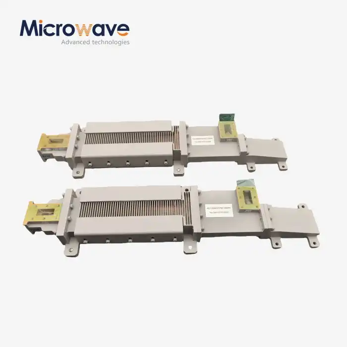
In flap or blade attenuators, a resistor card is put into the waveguide so that it is not in the path of the signal. The depth of entry is controlled by a linear actuator or a screw device. They are smaller and cheaper than rotating designs, but they introduce a phase shift that changes depending on the attenuation setting. This is fine for measuring power, but it's a problem for measuring vectors. When attenuation levels are high, VSWR performance usually goes down because the blade makes impedance gaps.
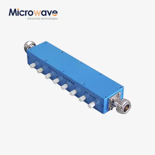
Step attenuators don't allow for ongoing change; instead, they offer set, switchable reduction values. Different resistance parts or waveguide routes are chosen by internal switching systems. When consistency and remote control are more important than endless resolution, these units work great in automatic test equipment. Binary-weighted systems allow for exact digital control, but in high-cycle uses, mechanical relay lives need to be taken into account for upkeep.
How to Choose the Best Waveguide Variable Attenuator for Your Application
Instead of just choosing the highest performance grades, it's important to make sure that the waveguide variable attenuator requirements match the real test conditions before making a purchase choice. We walk our customers through a methodical review process that finds the best mix between their professional needs and their budget.
Critical Evaluation Parameters
Matching the frequency range is the most important thing to do. The size of the waveguide determines the cutoff frequencies. Trying to operate below the cutoff results in evanescent wave propagation and useless loss, while operating at too high a frequency causes multimode propagation that invalidates readings. Make sure that your test frequencies are well within the band that the maker has stated, leaving room for filter roll-off traits.
Laboratory and outdoor uses are different in how they handle power. A desktop VNA usually sends out milliwatts, but testing a radar emitter might use kilowatts of burst power. Find the average and high power levels, as well as safety factors for signs that are mirrored when the load is not met. Our manufacturing process is ISO 9001:2015 approved, which means that purchase engineers can trust the power rates that are written down for risk and insurance reasons.
The test scope is set by the attenuation range and precision. 80 dB of dynamic range with 0.1 dB steps may be needed to measure receiver sensitivity, but only 20 dB with 1 dB precision is needed for simple gain compression tests. Over-specificating costs money that isn't needed, and not-specificating causes solutions that hurt the quality of the data.
Waveguide Versus Coaxial Trade-Offs
It's easy to use coaxial variable attenuators because they don't need waveguide flanges and adapters to connect to current test lines and plugs. Because they serve more markets, coaxial components often have shorter lead times. Because they cost less per unit, they are good for low-power uses below 18 GHz.
Above 26 GHz, waveguide solutions are needed because coaxial line losses make devices useless. Our sealed waveguide attenuators can handle shaking, temperature cycles, and humidity, all of which would damage coaxial connections. This gives them an edge in tough settings. Customers in the military and aircraft industries like that waveguide flanges don't lose their performance after thousands of mating cycles like coaxial connections do.
When you figure out the total cost of ownership, you should include upkeep and testing times. Waveguide attenuators only need to be recalibrated every once in a year or every other year, while coaxial units may need to be checked every three months. Over the life of a system, the costs of lab time and tools used for these calibrations add up.
Supplier Evaluation Criteria
When it comes to fine parts, brand history is important. Well-known companies like Keysight Technologies and Anritsu have built their names by making measurement tools for decades. This makes it easier to get application help and parts in the future. New providers may be able to save you money, but test results and quality methods need to be carefully checked.
Our 24-meter microwave lab and measurement tools, which can go up to 110 GHz at Advanced Microwave Technologies Co., Ltd., show that we have the facilities to meet the requirements for our components. Customers trust us more when they know we test the things we make ourselves instead of depending on test reports from outside contractors. Our RoHS compliance and ISO certifications meet the quality and environmental standards that buying teams need to keep track of.
Integrating Waveguide Variable Attenuators into Microwave Testing Systems
Whether waveguide variable attenuators meet requirements or become sources of errors depends on how well they are installed. Both mechanical and electrical integration need lab workers to pay close attention to details that they might miss when they are in a hurry to set up a test.
Installation Best Practices
Aligning waveguide flanges affects insertion loss and VSWR. The mating sides must be flush and free of RF gaps that create echoes. UG-style and PDR 70 flanges include accurate adjustment pins to center them when torqued. We recommend utilizing precise torque tools and following the manufacturer's guidelines, which are generally 20–40 inch-pounds depending on the flange size. Lips bend and electrical performance drops when overtorqued. Under-torque causes holes.
Closing and electrical connection depend on the gasket choice. Indium- or silver-plated gaskets transmit electricity better, although they must be changed when disassembled. Reusable metal seals can save maintenance but increase entrance loss. Laboratory equipment can employ reused gaskets, while sealed outside systems require single-use materials.
System Integration Considerations
Supporting flanges prevents physical stress. Unsupported waveguide pieces droop, which can cause them to be out of line and shatter at the connecting points. Mounting clamps near the attenuator distribute weight and hold it in place during temperature and vibration changes.
By matching the attenuator's frequency spectrum to neighbouring components, you may avoid unexpected performance issues. Curved elements that gradually change size are needed to switch waveguide bands; abrupt changes produce reflections. Signal integrity is maintained by arranging signal lines to stay on the same band during critical measurements.
Various regulators have various control systems. Manual micrometre adjustment works well for a tabletop application where the user determines the measuring circumstances. Motorized versions with USB, GPIB, or Ethernet connectors allow LabVIEW or Python programs to automate testing. By specifying interaction demands upon purchasing, costly upgrades or external controllers can be avoided.
Maintenance Protocols and Longevity
Regular maintenance extends product life. Check mechanical equipment for backlash regularly. Backlash is the little movement that occurs when the movement direction changes, making the setting uncertain. Too much backlash indicates worn drive parts that need to be changed before accuracy diminishes.
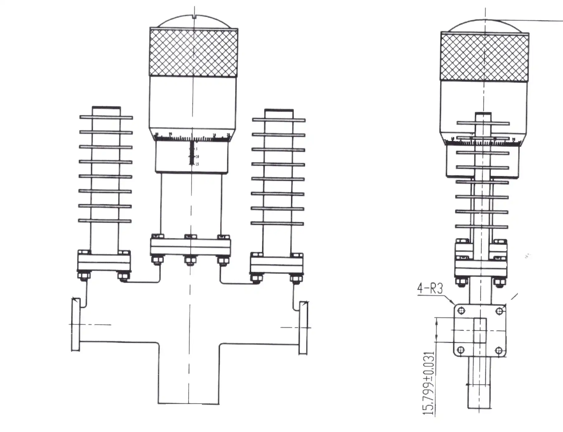
Use rubbing alcohol and lint-free brushes to carefully clean RF touch locations. Pollution and oxidation increase VSWR and insertion loss. Avoid harsh cleaning agents that remove metal or damage sensitive surfaces. Our customer support staff covers product maintenance throughout training.
Environmental exposure accelerates wear outside labs. Humidity corrodes interior parts, and temperature variations stress mechanical systems. Shelters and weather sealing prolong the lifespan of attenuators in uncontrolled areas. Sealable versions are available for outdoor test ranges and ground stations.
Real-World Application Insights
Aircraft radar calibration is a challenging use case we've worked with. A major defence contractor used our X-band rotary vane attenuators in automated phased array antenna module testing equipment. Phase stability was crucial since phase errors would affect beamforming computations. Despite daily adjustments, attenuators were accurate within ±0.15 dB over three years of production testing.
Ground installations for satellite transmission face several issues. A commercial user wanted Ka-band attenuators to mimic rain fading during bit error rate testing. The structure has to be sealed to resist -20°C to +50°C for high-frequency operation (26.5-40 GHz) and outside installation. The 40-dB range and waterproof casing of our WR-28 flap attenuators allowed testing year-round without moving the equipment.
Research uses typically exceed frequency restrictions. A university physics department studying terahertz transmission requested W-band attenuators with an insertion loss of 0.3 dB at their lowest over 75 to 110 GHz. Production was tough due to the narrow waveguide dimensions and strict accuracy; our 110 GHz testing equipment ensured performance before delivery. Working together led to published research and additional orders as the project progressed.
Conclusion
Some of the most important parts of precision microwave test devices used in military, aircraft, satellite communications, and studies are waveguide variable attenuators. They can direct signals accurately and steadily at high frequencies and power levels, which makes them impossible to replace in situations where cable options don't work. To make a good purchase, you need to balance scientific requirements like frequency range, power handling, and attenuation accuracy with practical ones like wait time, customization needs, and long-term support. We shared these ideas based on 20 years of experience that Advanced Microwave Technologies Co., Ltd. has had in making precise RF parts. Our methods are ISO-certified, and we can test a lot of things to make sure that the parts we sell meet written standards that purchase experts can rely on.
FAQ
Q1: What differentiates rotary vane from flap-style variable attenuators?
By rotating a resistance element, rotary vane waveguide variable attenuators change the attenuation based on polarization principles. This provides better phase stability and consistent VSWR across sets. When flap designs are used, a resistive blade is inserted into the waveguide. This makes the design smaller and cheaper, but it also changes the phase shift and lowers the VSWR when the loss is high. Rotating designs are needed for tasks that need to measure vectors or operate in phase-coherent mode, but flap versions can be used for simple power measurements.
Q2: Can these attenuators handle high-power radar testing applications?
How much power it can handle varies depending on the design and frequency band. Standard types can handle continuous wave power of several kilowatts to hundreds of watts, which is much more than coaxial options. High-power versions have ceramic absorbing parts and better heat sinking to keep them from breaking down due to heat. Always compare the power values to your highest and lowest levels, making sure to include safety gaps for power that is lost when impedances don't match.
Q3: How does frequency affect attenuation accuracy and specifications?
Because they are built on polarization, rotary vane attenuators keep attenuation that is pretty constant across frequencies. However, VSWR may change across the band. Flap-style units have absorption that changes with frequency and needs adjustment factors. Good makers give users calibration data at a number of frequency points within the given range. This lets them make changes for more accurate readings or choose frequencies where performance is best.
Partner with ADM for Your Waveguide Variable Attenuator Requirements
Advanced Microwave Technologies Co., Ltd is ready to be your reliable source for waveguide variable attenuators. They offer both high-quality products and quick customer service. Our large catalogue covers all standard frequency bands, from L to W. Additionally, our OEM services can meet unique needs that standard goods can't. Each attenuator comes with full test data that can be traced back to our 110 GHz measurement tools. This gives your quality assurance teams the proof they need. After the sale, our engineering staff helps with installation, integration, and NIST-traceable testing, which extends the life of parts and keeps measurements accurate. Purchasing managers like how easy it is to place orders with us, whether they need a few prototypes for research and development or a lot of products with planned supplies. You can talk to our applications engineers about your unique needs by emailing craig@admicrowave.com. They are familiar with the technical details and the buying stresses you face every day.
References
1. Pozar, D.M. (2011). Microwave Engineering, 4th Edition. Hoboken: John Wiley & Sons, Inc.
2. Harvey, A.F. (1963). Microwave Engineering. London: Academic Press.
3. Rizzi, P.A. (1988). Microwave Engineering: Passive Circuits. Englewood Cliffs: Prentice Hall.
4. Saad, T.S. (1971). Microwave Engineers' Handbook, Volume 1. Dedham: Artech House.
5. Montgomery, C.G., Dicke, R.H., and Purcell, E.M. (1948). Principles of Microwave Circuits. New York: McGraw-Hill Book Company.
6. Collin, R.E. (1992). Foundations for Microwave Engineering, 2nd Edition. New York: IEEE Press.