Microwave Parabolic Antenna Design Guide
A microwave parabolic antenna guides electromagnetic waves with a curvy parabolic reflector. This lets high-gain signals travel and be received across UHF and SHF bands. These antennas are widely used in radar systems, 5G backup, and satellite communications. They turn circular waves into collimated beams by carefully placing the feed at the reflector's focus point. Their high level of directivity solves important problems like weak signals over long distances, crowded airwaves, and limited bandwidth in mission-critical wireless infrastructure. Procurement teams can find solutions that meet strict performance standards if they understand the basics of how they were designed.
Understanding Microwave Parabolic Antenna Fundamentals
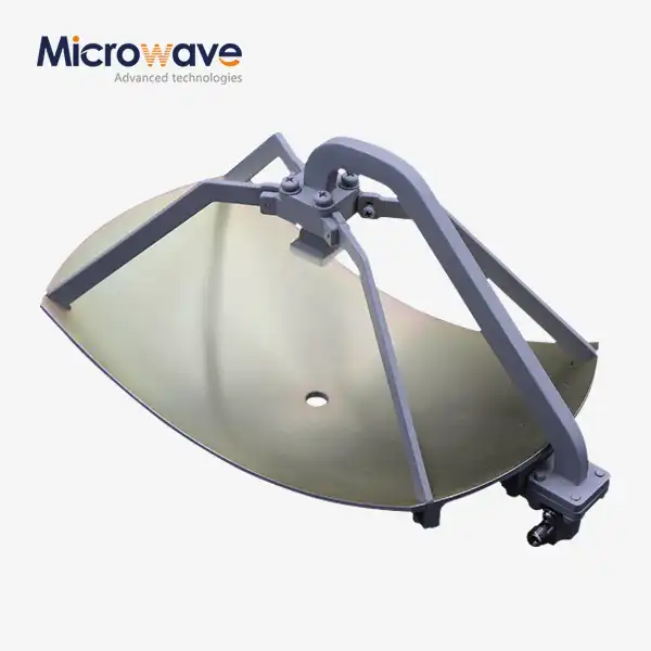
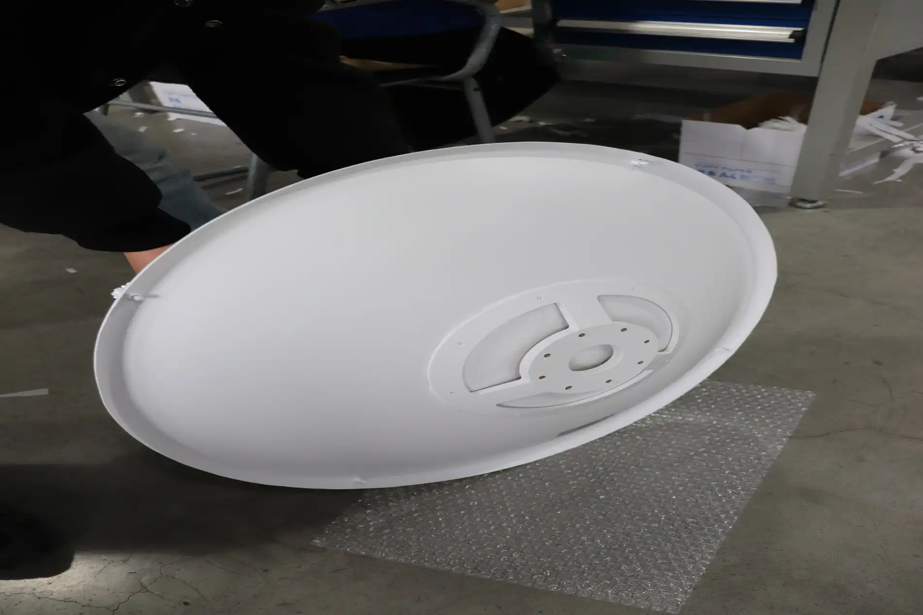
Since the middle of the 20th century, microwave parabolic antennas have been the foundation of radio frequency communications. They have been used in everything from early satellite ground stations to modern point-to-point links on land. At their core, these devices use parabolic geometry: a feed horn placed at the focus point of the reflector sends out circular waves that hit the curved surface and come out as parallel plane waves. This beam-forming device gives very high gain, often more than 30 dBi, in small sizes. This makes communication stable over long distances where other antenna types fail.
Operational Principles and Signal Focusing
The mathematical accuracy of the parabolic reflector ensures that every ray path from the feed to the edge of the reflector stays the same length electrically. The phase coherence focuses the energy that is released into narrow beamwidths, which are usually between 1 and 10 degrees, but this depends on the size and frequency of the opening. When the signal is received, the arriving plane waves merge at the focus point, which is where the feed picks up the most power. Because they work well in both directions, parabolic designs are perfect for full-duplex communication links that work from 2 GHz to 80 GHz. This includes C-band satellite downlinks, X-band military radar, and the new E-band wireless backup.
Key Performance Parameters for Technical Evaluation
Gain is the antenna's ability to boost signal strength compared to an isotropic radiator. It is found by multiplying 10 log (η(πD/λ)²), where D is the reflector's width and λ is its wavelength. Increasing the width by two times raises the gain by about six decibels, but at higher frequencies, surface accuracy is very important—Ka-band systems need reflection errors of less than 0.5 mm. Sidelobe levels are shown by radiation patterns and affect how well interference is blocked. ETSI Class 3 and Class 4 antennas block off-axis radiation below -30 dBc, which is very important for dense network deployments. Application suitability is based on frequency range. Dual-polarized types can handle both vertical and horizontal transmission at the same time using orthomode transducers (OMT), which doubles spectral efficiency by canceling out cross-polarization interference (XPIC).
Real-World Deployment Scenarios Across Industries
5G base stations use 70 GHz E-band parabolic antennas to send multi-gigabit data streams between sites in cellular backup networks. This way, cable construction costs are avoided in urban hubs. Satellite VSAT stations use Ku-band dishes (12-18 GHz) with slippery radomes to keep the marine internet connection going even when the weather is bad. In meteorological radar systems, 3-meter S-band mirrors on moving pedestals scan the patterns of precipitation with beamwidths that are accurate enough to pick up microbursts up to 200 kilometers away. Different uses need different requirements. For example, marine systems need metal alloys that don't rust, and air traffic control radars need monopulse tracking feeds for angle resolutions of less than one degree.
Comparing Microwave Parabolic Antennas with Other Antenna Types
Choosing an antenna depends on how well you can balance gain, size, bandwidth, and how hard it is to place. Horn antennas work well in a wide range of frequencies (40% fractional bandwidth), but they aren't directional enough for long-distance links, and their 15-20 dBi gain means that waveguide openings beyond 10 GHz are too big to be useful. Patch arrays can be mounted conformally on airplane fuselages, but they have low power handling and narrow bandwidths (5–10%), which are problems for high-throughput backup. Through parasitic elements, Yagi-Uda antennas get a modest gain, but their performance is frequency-sensitive, making them unsuitable for wideband satellite transceivers.
Why Parabolic Designs Excel in Long-Range High-Gain Applications
In point-to-point microwave situations where link budgets need 35–50 dBi gain to close 50-kilometer land hops or 38,000-kilometer GEO satellite paths, microwave parabolic antennas are the most common choice. Their adjustable aperture lets you target specific gain levels. For example, a 1.2-meter dish gives you 42 dBi at 18 GHz, while a 3.7-meter reflector gives you 52 dBi at the same frequency. In contrast to phased arrays, which need complicated beamforming networks, parabolic systems achieve directivity through passive shape, which lowers the cost of parts and the amount of loss during insertion. Advanced cover designs that meet ETSI EN 302 217 standards allow channel packing with links next to each other, set 0.5 degrees apart. This makes the most of the spectrum in busy city passageways.
Suitability Within 5G and Advanced Wireless Ecosystems
As 5G backhaul moves to millimeter waves, the need for small, high-performance parabolic antennas that work in V-band (57–71 GHz) and E-band has grown. Terabits of gathered data are sent over these links instead of dense small-cell networks, where building fiber out would be too expensive. Dual-polarized models with OMT feed units can double capacity without needing extra frequency rights, reaching 2 Gbps per channel in 56 MHz bandwidths. Integrated antenna radio units (IARUs) from different manufacturers now come with transceivers mounted directly behind reflectors. This gets rid of the need for waveguide runs, which lose 3 to 5 dB at 80 GHz.
Designing and Optimizing Microwave Parabolic Antennas: Best Practices
The parabolic equation z = r²/4f is used to describe reflector geometry. Here, f is the focal length and r is the horizontal distance from the axis. Deeper dishes (with low f/D ratios close to 0.3) focus energy but make feed design harder because they let in a lot of light. Shallow profiles (with f/D = 0.6) make feed coupling easier but lose energy to spillover. Choosing the right material is important because it affects the weight, stiffness, and accuracy of the surface. For example, spun aluminum is a cheap way to make things with widths under 2 meters, and carbon fiber composites can keep limits of less than 1 millimeter in 4-meter Ku-band earth stations even when they are heated and cooled many times.
Feed Positioning and Illumination Optimization
It's important to be very precise when placing the feed horn—a 1 mm vertical shift at 24 GHz lowers the gain by 0.5 dB and changes the radiation pattern. Corrugated horns that make hybrid HE₁₁ modes get symmetrical E-plane and H-plane beamwidths, which light up the reflector evenly while keeping cross-polarization below -30 dB. The best lighting lowers the edge intensity to -10 dB compared to the center, combining the efficiency of the opening (usually 65–75%) with the reduction of sidelobes. In dual-reflector Cassegrain setups, the feed is moved behind the main dish. This makes it easier to see and allows for small outdoor unit integration for telecom purposes.
Troubleshooting Common Performance Issues
Connector rust at the feed interface is a common cause of signal loss. Waveguide flange torque should be checked every three months, and moisture should be checked for entry through pressurization ports. RSSI (received signal strength indicator) drops when something isn't lined up right. Millimeter-wave links need to be able to point accurately within 0.1 degrees, which means they need GPS-assisted orientation tools and mounts that don't vibrate. When interference from nearby channels happens, it means the front-to-back ratio isn't good enough. This problem can be fixed by moving to higher ETSI class microwave parabolic antennas with better rear shield absorption. In coastal areas, wind-induced sway is the main cause of outages. To keep the structure stable in 150 km/h gusts, strengthened mounting clamps and aerodynamic radomes are needed to make sure that the link is always available.
Case Studies Demonstrating Successful Implementations
A big European phone company put 10,000 dual-polarized 0.6-meter antennas all over its metro network. Using an 80 GHz E-band frequency, they were able to achieve 10 Gbps of combined backup capability. The project called for ETSI Class 4 radiation patterns, which allowed sites to be 250 meters apart without having to do coordination studies. This cut the time it took to launch by 40%. In contrast, a satellite internet provider in rural Alaska chose 2.4-meter C-band mirrors with hot radomes to fight snow buildup, which used to slow down service by 15% in the winter. These cases show how matching antenna specs to factors in the environment and rules and regulations makes sure that network behavior is reliable.
Procurement Guide: How to Choose and Buy Microwave Parabolic Antennas
To start evaluating microwave parabolic antennas, you need to set your link budget limits. First, use the Friis equation to find the free-space path loss. Next, choose the minimum antenna gain that will meet your fade margin goals, which are usually 20 to 30 dB for 99.99% availability. Check the frequency band assignments with the FCC or ETSI to make sure they are in line with transmission masks and EIRP limits. Site factors must be taken into account in mechanical requirements. For example, IEC 60721-2-4 environmental rates and wind survival speeds of more than 200 km/h are needed for tower-mounted installations in storm zones.
Balancing Performance Specifications Against Budget Constraints
Due to their precise production and built-in tracking pedestals, high-gain 3-meter earth station antennas cost $15,000 to $30,000. On the other hand, 0.6-meter telecom backup dishes cost $800 to $1,500, based on whether they have a radome or not and the polarization choice chosen. Buyers should look at the total cost of ownership. For example, Class 4 antennas cost 25% more than Class 2 versions, but they don't have to pay frequency coordination fees in crowded markets, so the extra cost is paid back in 18 months. When compared to split-mount setups, ODU-integrated solutions cut installation work by 60%. This is made up for by faster rollout plans that cover higher component costs.
Global Manufacturers and Custom OEM Solutions
Leading providers offer standard product lines that cover frequencies from 2 to 86 GHz and have lead times of 4 to 8 weeks, making them perfect for regular network growth. Custom OEM contracts are used to meet specific needs. For example, military companies buy ruggedized antennas that are certified to MIL-STD-810 for shock and vibration, and research institutions ask for ultra-wideband feeds that cover octave bandwidths for spectrum tracking. We keep our ISO 9001:2015 and ISO 14001:2015 certifications at Advanced Microwave Technologies Co., Ltd (ADM), which shows that we care about quality management and the environment in all of our manufacturing processes. Our 24-meter anechoic room lets us measure far-field patterns up to 110 GHz, which checks the gain and sidelobe performance of the product before it ships. Within three weeks, prototyping services send evaluation units so that customers can test them in the field before committing to large orders.
Bulk Purchasing Considerations and Warranty Coverage
Volume savings usually start at 50 units, and at 500 units, tiered pricing lowers the price per unit by 15 to 30 percent. Due to the time it takes to get raw materials, lead times go up to 12 to 16 weeks for sales of more than 1,000 antennas. Standard guarantees protect you against production flaws for 24 months. Extended warranties that last for five years cost 8–12% more. Service-level agreements should include MTBF (mean time between failures) measures. For example, expensive antennas promise to work for 100,000 hours with failure rates below 0.5% per year. Letters of credit with inspection clauses are often used as payment terms for foreign purchases. These protect buyers against nonconformance and reassure sellers that they will be paid upon delivery.
Conclusion
Microwave parabolic antennas are still very important for military radar systems, 5G infrastructure, and satellite communications. Their precision-engineered mirrors give them unmatched gain and directivity. A good purchase combines technical requirements like frequency range, polarization, and ETSI class with environmental durability and costs over the product's lifetime. Knowing the basics of design, like how to choose materials and how to light feeds, helps engineering teams make the most of their link funds and fix problems in the field. As more business networks use millimeter-wave bands, there is a greater need for small, high-performance antennas that can meet strict legal requirements and be set up quickly.
FAQ
Q1: How does a radome impact antenna performance in harsh weather?
Radomes keep mirrors safe from ice buildup and wind loads that can detune systems, but they add 0.3 to 0.8 dB of insertion loss, based on the material (ABS vs. fiberglass). Hydrophobic coats stop water films that make sound weaker when it rains a lot. The trade-off makes radome installation more likely in seaside or mountainous areas where mechanical safety is more important than slight signal loss.
Q2: What differentiates single-polarized from dual-polarized configurations?
Single-polarized antennas only send signals on one plane, either vertically or horizontally. Dual-polarized types use orthomode transducers to handle both at the same time. This design doubles the link capacity using the same frequency bands and XPIC technology, getting 2x2 MIMO speed without the need for extra spectrum licensing. This is important for backup networks that don't have a lot of bandwidth.
Q3: Why does the ETSI radiation pattern class matter for link planning?
Sidelobe suppression levels are set by ETSI classes. For example, Class 3 and Class 4 antennas stop off-axis radiation below -28 dBc, which lets urban sites have close channel spacing (0.5 degrees between them) without having to coordinate interference. In a crowded spectrum, lower classes run the risk of disrupting links next to them, which could lead to violations of the law and a drop in service.
Partner with ADM for High-Performance Microwave Parabolic Antenna Solutions
With more than 20 years of experience making RF components, Advanced Microwave Technologies Co., Ltd is ready to help you buy a microwave parabolic antenna. Our engineering team makes unique antenna sets that work with frequencies from 0.5 to 110 GHz. These are backed by ISO 9001 quality systems and RoHS compliance. Our OEM services offer quick prototypes, in-depth technical advice, and the ability to make large quantities of whatever you need. This includes ruggedized dual-polarized dishes for satellite ground stations and small E-band mirrors for 5G backhaul. Email our experts at craig@admicrowave.com to talk about your needs, get performance datasheets, or set up sample tests. As a reliable provider of microwave parabolic antennas, we guarantee on-time delivery, reasonable price, and full help after the sale to keep your mission-critical systems running.
References
1. Balanis, Constantine A. Antenna Theory: Analysis and Design, 4th Edition. Wiley, 2016.
2. Milligan, Thomas A. Modern Antenna Design, 2nd Edition. IEEE Press, 2005.
3. European Telecommunications Standards Institute. ETSI EN 302 217: Fixed Radio Systems; Characteristics and Requirements for Point-to-Point Equipment and Antennas, 2017.
4. Stutzman, Warren L., and Gary A. Thiele. Antenna Theory and Design, 3rd Edition. Wiley, 2012.
5. IEEE Antennas and Propagation Society. IEEE Standard for Definitions of Terms for Antennas (IEEE Std 145-2013), 2013.
6. Kraus, John D., and Ronald J. Marhefka. Antennas for All Applications, 3rd Edition. McGraw-Hill, 2002.